ORIGINAL RESEARCH
Compliance‑aware engineering process plans: the case
of space software engineering processes
Julieth Patricia Castellanos‑Ardila1 · Barbara Gallina1 · Guido Governatori2 Accepted: 14 February 2021
© The Author(s) 2021
Abstract
Safety-critical systems manufacturers have the duty of care, i.e., they should take correct steps while performing acts that could foreseeably harm others. Commonly, industry standards prescribe reasonable steps in their process requirements, which regulatory bodies trust. Manufacturers perform careful documentation of compli-ance with each requirement to show that they act under acceptable criteria. To facili-tate this task, a safety-centered planning-time framework, called ACCEPT, has been proposed. Based on compliance-by-design, ACCEPT capabilities (i.e., processes and standards modeling, and automatic compliance checking) permit to design Compliance-aware Engineering Process Plans (CaEPP), which are able to show the planning-time allocation of standard demands, i.e., if the elements set down by the standard requirements are present at given points in the engineering process plan. In this paper, we perform a case study to understand if the ACCEPT produced mod-els could support the planning of space software engineering processes. Space soft-ware is safety and mission-critical, and it is often the result of industrial cooperation. Such cooperation is coordinated through compliance with relevant standards. In the European context, ECSS-E-ST-40C is the de-facto standard for space software production. The planning of processes in compliance with project-specific ECSS-E-ST-40C applicable requirements is mandatory during contractual agreements. Our analysis is based on qualitative criteria targeting the effort dictated by task demands required to create a CaEPP for software development with ACCEPT. Initial obser-vations show that the effort required to model compliance and processes artifacts is significant. However, such an effort pays off in the long term since models are, to some extend, reusable and flexible. The coverage level of the models is also ana-lyzed based on design decisions. In our opinion, such a level is adequate since it responds to the information needs required by the ECSS-E-ST-40C framework.
Keywords Process compliance checking · Software process plan · ECSS-E-ST-40C
* Julieth Patricia Castellanos-Ardila julieth.castellanos@mdh.se
1 Introduction
Safety-critical systems manufacturers have the duty of care1 (Ladkin 2019), i.e., they should follow accepted practices of reasonable care, usually found in industry standards (Generowicz 2013). Failure or inadequate compliance with such standards could lead to legal risks, i.e., penalties (Cusumano 2004) and prosecutions (Ingolfo et al. 2011). For example, in 2015, The Volkswagen “Dieselgate” scandal (Walkin-shaw 2017), i.e., emissions levels of the cars were not complying with emission standards, resulted in huge lost to the company (Blackwelder et al. 2016). Compli-ance with industry standards is relevant evidence for a jury to consider in a prod-uct liability action (Schwartz 2000). In England, the Health and Safety Executive has used compliance with IEC 61508 (IEC 2010) as a guideline for bringing legal actions if harm is caused by safety-critical systems (Ladkin 2019).
Industry standards demand documented evidence of responsibilities and agree-ments (Moyón et al. 2020). Usually, they place requirements on engineering pro-cesses (Eastaughffe et al. 1999), which should be planned at the beginning of the engineering activities (Gallina et al. 2018). Compliant engineering process plans are used to coordinate and track engineering progress, support contractual relation-ships between partners and agreements with certification bodies. In the context of the European project AMASS (Ruiz et al. 2016; de la Vara et al. 2019), a safety-cen-tered planning-time framework, called ACCEPT (Automated Compliance Checking of Engineering Process plans against sTandards) (Castellanos Ardila 2019a, b), has been proposed to facilitate process compliance checking tasks. ACCEPT is based on Compliance-by-design (Lu et al. 2007), an approach aimed at integrating com-pliance requirements at design time, permitting to resolve comcom-pliance violations in engineering process plans before they are executed. ACCEPT is supported by rules-based technologies to automatically check if a compliance-aware engineering pro-cess plan (CaEPP) is designed, i.e., if the elements set down by the requirements (e.g., tasks, personnel, work products, techniques, and tools, as well as their proper-ties) are present at given points in the engineering process plan. A CaEPP can show how and when the evidence will be produced, taking into account all the process-related requirements or their tailoring (i.e., adapted to the specific project conditions in a compliant form). A CaEPP is able to demonstrate intentional compliance (Siena et al. 2008), i.e., planning-time allocation of responsibilities, such that if every actor fulfills its duties, then the compliance is ensured.
ACCEPT uses Formal Contract Logic (FCL) (Governatori 2005), which pro-vides a framework that unambiguously represents normative knowledge, i.e., obligations, prohibitions, and permissions. ACCEPT also uses the compliance checker Regorous (Governatori 2015), which provides an algorithm that deter-mines whether an annotated process model is compliant with a specific set of FCL rules. The annotated process models required by Regorous, i.e., process
1 In tort law, a duty of care is a legal obligation which is imposed on an individual requiring adherence
to a standard of reasonable care while performing any acts that could foreseeably harm others (Icheku 2011).
enriched with compliance effects through annotations representing the formalized requirements, is provided via SPEM 2.0 (Systems & Software Process Engineer-ing Metamodel) (OMG 2008). We chose SPEM 2.0, as opposed to other process modeling notations, for several reasons. (1) SPEM 2.0 is a standardized language, based on the Unified Modeling Language (UML) (OMG 2017). (2) SPEM 2.0-like artifacts can be captured freely via Eclipse Process Framework Composer (EPF-C) (Eclipse Foundation 2018) (recently ported to Eclipse Neon 4.6.3 (Javed and Gallina 2018a)). (3) SPEM 2.0 has the ability to capture several types of information. (4) SPEM 2.0 provides variability mechanisms that can be exploited for flexible process derivation. Such mechanisms are currently tool-supported via the composition of EPC-C with BVR (Base Variability Management Tool (SIN-TEF 2016)) (Javed and Gallina 2018b) included in the AMASS tool platform (de la Vara et al. 2020). (5) SPEM 2.0 elements can also be customized to permit the definition of a variety of artifacts. All these characteristics facilitate the mod-eling of process-related compliance artifacts, i.e., engineering processes and their elements, as well as standards requirements and their derived rulesets, anno-tated process plans, and workflows representations, which can be also reused, tailored and explicitly documented. EPF-C models can be ported to other tools, via model-driven transformations. Finally, SPEM 2.0 is widely accepted by the research community (Ruiz-Rube et al. 2012) and industry (Baumgarten et al. 2015).
In this paper, we perform a case study to understand if the ACCEPT produced models could support space manufacturers’ needs in planning space software engi-neering processes. Space software is safety-critical since a failure could cause a mission disaster leading to financial losses, environmental pollution, and people’s endangerment in case of manned missions (Rantala et al. 2017). Moreover, space software production is frequently the result of industrial cooperation. For example, the European space context consists of space agencies often acting as customers in projects, and companies, which act as suppliers, or as intermediate customers for subcontractors (Lill 2018). Meeting the highest levels of industry standards helps to coordinate such cooperation. In this context, ECSS-E-ST-40C is the de-facto stand-ard for space software production. Thus, the planning of processes in compliance with project-specific ECSS-E-ST-40C applicable requirements is mandatory during contractual agreements. We have selected a portion of the ECSS-E-ST-40C (ESA 2009a) related to the design of the software items to perform our analysis, which is based on a set of well-defined qualitative criteria defined in Ghanavati et al. (2008). In particular, we target the effort dictated by task demands required to create a CaEPP for software development with ACCEPT. Initial observations show that the effort required to model compliance and processes artifacts is significant. However, such an effort pays off in the long term since models are, to some extend, reusable and flexible. The coverage level of the models is also analyzed based on design deci-sions. In our opinion, such a level is adequate since it responds to the information needs required by the ECSS-E-ST-40C framework.
The paper is organized as follows. In Sect. 2, we provide essential background. In Sect. 3, we present the case study design. In Sect. 4, we present the data collection. In Sect. 5, we present the case study analysis. In Sect. 6, we discuss the findings. In
Sect. 7, we present related work. Finally, In Sect. 8, we present the conclusion and future work.
2 Background
In this section, we present essential background information required in this paper.
2.1 Compliance with industry standards
Industry standards offer frameworks that encompass adequate practices refined by experts from historically successful experiences (Harkiolakis 2013) as well as knowledge and awareness of public policy, societal norms, and preferences (Leveson 2016). Organizations comply with industry standards (sometimes augmented with internal guidelines) to minimize legal risks (Kienle et al. 2012) since compliance is the demonstration that the organization acts under well-defined and acceptable criteria. In some industries, a compliance certification is mandatory to be able to sell products on a specific market, e.g., medical devices (U.S. FDA 1906). Compliance is also a mark that customers trust. For example, in space, standards requirements are intended to support the contractual negotiation by helping customers to formu-late their requirements and suppliers to prepare their responses and to implement the work (ESA 2009b). Contracts are legally binding documents in which development freedom becomes limited. Thus, non-compliance is harmful to the success of organ-izations. In the remaining part of this section, we recall essential information regard-ing software process standards, and we focus on the software engineerregard-ing standard that regulates the European space context.
2.1.1 Software process standards
In the past, software companies vacate liability for software errors by licensing it to a user that agreed that the company would not be liable for damages caused by errors in the code (Denning and Tedre 2019). This policy contributed to enforce the computer revolution. However, the software was limited to provide simple tasks and sometimes computational power for complex systems. Nowadays, the software is used to control most systems (including physical) involving potentially large and even catastrophic loses (Leveson 2020). Consequently, software projects are becom-ing critical in terms of legal aspects, e.g., software not delivered in time or with ill-defined functionality could lead to legal claims (Kalus and Kuhrmann 2013). In the safety-critical context, legal aspects are also related to each activity performed in its production (Cosgrove 2001; Buglione et al. 2010). The reason is that a well-defined process would make it difficult to exclude significant aspects of the soft-ware engineering aspects. Examples of inadequate softsoft-ware engineering process practices have been considered as one of the factors that cause Therac-25 radiother-apy machine’s massive overdose (Leveson et al. 1995) and the failed launch of the ARIADNE 5 (Dowson 1997). Choices seem not to be either deliberately planned
in the definition of the features created to force the plane BOEING 737-MAX to nose down, causing fatal accidents (Cruz and de Oliveira Dias 2020). Sound engi-neering processes present a structured collection of practices (SEI 2011). Compa-nies that follow the process-related frameworks prescribed by industry standards tend to achieve more consistent results (O’Regan 2018). Legal risk can also be pre-vented since proofs of compliance can demonstrate that companies have taken cor-rect steps while performing acts that could foreseeably harm others (Cosgrove 2001; Kienle et al. 2012). Software process standards do not restrict organizations from using a particular development lifecycle. Instead, the process framework focuses on what needs to be done. Sometimes, who should be involved in the process and the recommended techniques and tools to be used to achieve desirable results are also prescribed. Route maps may be indicated, but exact specifications on how the process should be done usually are not provided. In addition, software with high requirements, such as safety, requires detailed documentation according to regula-tions, which may imply the creation of very formal software processes (Kalus and Kuhrmann 2013). For this reason, a software process engineer is responsible for the selection, composition, and correct documentation of adequate software process ele-ments aimed at achieving the required process goals (Gallina et al. 2016).
2.1.2 ECSS standards: focus on software engineering
The European Cooperation for Space Standardization (ECSS) developed a set of standards for use in all European space activities. The ECSS standard system includes three branches, i.e., Management (M), Engineering (E), and Product Assur-ance (Q). Handbooks (HB) guide the application of the requirements. The software engineering handbook, ECSS-E-HB-40A (ESA 2013), states that in a space soft-ware project, a customer-supplier business agreement should be established. The customer shall produce the project requirements documentation, which could be pro-duced by using the ECSS Applicability Requirements Matrix (EARM). The EARM should have the list of applicable ECSS requirements with identifiers, applicability condition, i.e., applicable without change (A), applicable with modification (M), not applicable (D), and new generated requirement (N). The supplier responds with the ECSS Compliance Matrix (ECM), indicating the compliance for each requirement provided in the EARM. Partial compliance needs to be detailed, such that the cus-tomer can assess the extent to which the objective of the ECSS is covered. Non-compliance also needs to be investigated in terms of feasibility and acceptability in the scope of the project. When a space project starts, the supplier has to identify a suitable software lifecycle process. Thus, discussions about the technical speci-fications based on the requirements baseline must start early in the lifecycle pro-cess (Ahmad et al. 2010).
In space software development, the requirements prescribed by the standard ECSS-E-ST-40C (ESA 2009a), which determines mission (non-safety) requirements on how the goals can be achieved, should be applied. Such requirements could be tailored, i.e., adapted for the characteristics of the project. For example, ECSS-E-ST-40C-Annex R, provides a pretailoring based on safety criticality categories, which rank from catastrophic to negligible (prescribed in ECSS-Q-ST-40C (ESA
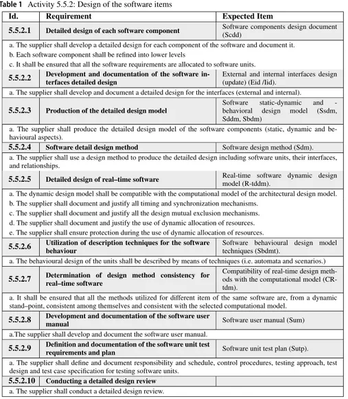
2017)). Thus, mission requirements have an inherent relationship with safety issues. Further tailoring should be analyzed in the scope of the project and its consequences assessed and documented. If requirements are tailored out, the associated expected outputs are also tailored out. Table 1 recalls a set of requirements from the phase
5.5. Software Design and Implementation Engineering Process, particularly the
activity 5.5.2. Design of Software Items. The inputs of this activity are the Technical Specification of the Software Components (TSSC), the Architectural Design (AD) the Design Justification (DJ), and the Preliminary Design Review (PDR). During the
detailed design review the expected items of every requirement are revised and
com-piled in eight work products, i.e., the DDF (Design Definition File), SDD (Software Design Document), CDR (Critical Design Review), TS (Technical Specification), ICD (Interface Control Document), SUM (Software User Manual), DJF (Design Justification File) and SUITP (Software unit-integration Test Plan).
2.2 SPEM 2.0
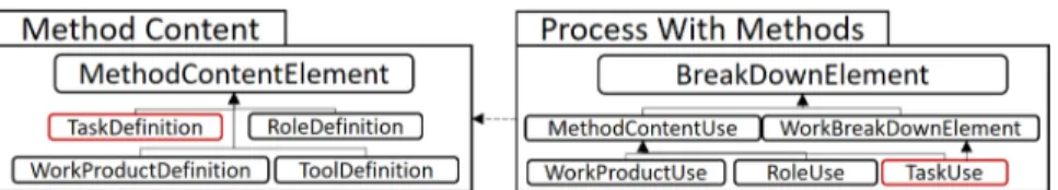
SPEM 2.0 (Software and Systems Process Engineering Metamodel) (OMG 2008) is a modeling language that defines the elements required to plan engineering pro-cesses. An engineering process is a sequence of units of work (e.g., tasks) that con-sume resources (e.g., employee time) to transform inputs (e.g., data, raw material) into outputs (e.g., products) (Boutros and Purdie 2014). SPEM 2.0 concepts are defined in separated UML (OMG 2017) packages that are interrelated. For example, the meta-class TaskDefinition, which belongs to the package MethodContent is used to describe assignable units of work. Instances of Task Definition can be applied in a process breakdown structure by defining a proxy with a TaskUse, a meta-class that belongs to the package ProcessWithMethods (both meta-classes are highlighted with red in Fig. 1). The same approach is used for the definition and use of roles and work products. Instead, a tool definition is used to specify the tool’s participation in a Task Definition. Guidance, which belongs to the package Managed Content, is a describ-able element that provides additional information to other elements. There are dif-ferent guidance kinds, e.g., concept and reusable asset. A Delivery Process, which belongs to the package Process Structure, describes an approach for performing a specific project. A Category is used to group elements in a recursive way. SPEM 2.0 supports variability management on breakdown structures representing processes as well as in content elements. In particular, we recall the variability mechanism called
extends, in which the method content element that extends the base method element
inherits the attributes of the extended base element.
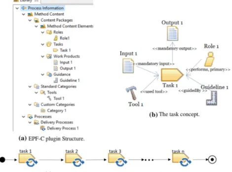
SPEM 2.0-like concepts can be modeled with an open-source tool, called Eclipse Process Framework Composer(EPF-C) (Eclipse Foundation 2018). In particular, EPF-C provides a Method Authoring, which is used to describe roles, tasks, work products, and guidance. EPF-C also has a Process Authoring, which is used to organize reusable process building blocks in the form of delivery processes. EPF-C implements the method plugin package, which defines capabilities for modulariza-tion and extensibility. Such plugins, which can contain libraries of method content and processes, are reusable. (see Fig. 2a). Conceptually, a task can be represented as a synergy between different process elements (see Fig. 2b). In EPF-C, the pro-cess’s partial execution semantics can be modeled with UML activity diagrams (see Fig. 2c).
2.3 FCL
FCL (Formal Contract Logic) (Governatori 2005) is a language that permits the formalization of normative requirements. An FCL rule has the form a1, ..., an⇒c ,
where r is the unique identifier of the rule, a1, ..., an are the propositions that
repre-sent the conditions of the applicability of such a rule, and c is the conclusion. The conclusion characterizes normative deontic effects, such as obligations, prohibitions, or permissions. FCL does not support contradictory conclusions but seeks to resolve conflicts. For instance, if it is sustainable support to conclude both c and −c , FCL does not conclude any of them. However, if the support for c has priority to the sup-port of −c , then c is concluded. Thus, an FCL rules designer has to identify pairs of rules with incompatible literals and define superiority relations, as follows:
Obligations and prohibitions are constraints that limit the behaviour of processes. As such, they can be violated. Permissions, which cannot be violated, can be used to determine that there are no obligations or prohibitions to the contrary. Hashmi et al. (2013) proposes the foundations for the normative requirements that constraint pro-cesses, which considers different types of obligations (based on the temporal valid-ity of norms and the effects of violating these obligations). Thus, an obligation is in force if the obligation is activated at a particular time point in a time interval. An
r ∶ a1, ..., an⇒c, and r�∶b1, ..., bn ⇒−c, then r�>r
obligation is considered to be non-persistent if it remains in force until it is termi-nated. Such obligation should be obeyed for the instant it is in force. In opposition, an obligation is considered persistent if it remains in force until it is removed. When a persistent obligation needs to be obeyed for the whole duration within the interval in which it is in force, it is called maintenance obligation. If achieving the content of the obligation at least once is enough to fulfill it, it is called achievement
obliga-tion. An achievement obligation is preemptive if it could be fulfilled even before the
obligation is in force. Otherwise, it is non-preemptive. An achievement obligation is
perdurant if, after being violated, the obligation is still required to be fulfilled.
Oth-erwise is non-perdurant. A prohibition corresponds to the negation of the content of an achievement obligation. The types mentioned above are adopted, and notated in FCL, as presented in Table 2.
2.4 Regorous
Regorous (Governatori 2015) is a process compliance checker that implements com-pliance by design (Sadiq et al. 2007), i.e., check requirements that are propagated into models of process plans. Regorous requires two specifications: (1) a rule base representing the regulation in FCL (recalled in Sect. 2.3), and (2) a state representa-tion of a process, i.e., a process enriched with semantic annotarepresenta-tions. Semantic anno-tations on process elements are literals that record data, resources, and other infor-mation used by machines to refer, compute, and align inforinfor-mation. The recorded information, which represents the effects caused by the tasks, is used by Regorous to perform compliance analysis. Two types of semantic annotations are necessary. The first one is State (t,n), which semantically annotates the set of facts in the com-putation to determine which rules fire (get active) for the n-th element in a trace t. A trace is a sequence of tasks in which a process can be executed. Consequently, obli-gations are in force after rules fire. The second one is Force(t,n+1), which contains the obligations that are in force but are not terminated in n-th element in the trace t. An obligation can be terminated if the deadline is reached, the obligation has been fulfilled, or if the obligation has been violated and is not perdurant. A process is fully compliant if all obligations are fulfilled, or if violated, they are compensated). For example, Fig. 3, shows a fictional FCL rule base and a compliance annotated process. As the figure depicts, the ruleset in FCL contains four rules. The first rule, Table 2 FCL rule notations
r1, implies the obligation of providing A. The second rule, r2, implies the obliga-tion of B given the provision of A. The third rule, r3, implies the permission to not provide C given the provision of B. And r4 implies the obligation of D given the provision of B. From the FCL rule base, we have four compliance effects, i.e., A, B, C, and D. As seen, the compliance effects are extracted from the formulas compos-ing the rules. The tasks in the process are annotated with the effects as follows. T1 is annotated with effect A, T2 is annotated with effect B, T3 is annotated with effect C, and T4 is annotated with effect D. To check compliance, we use the functions State and Force, as previously described. The State of the start point is empty because we have not defined any effect. After the start point, the compliance checking process is activated. Thus, the first rule is in force. The first task is expected to provide the effect A since there is the obligation to provide A. Then, we check the State after the task T1. As we see in the figure, T1 produces the effect A. So, the rule is fulfilled. Then, providing A forces the provision of B in T2. In the figure, we can see that T2 provides effect B. So, the second rule is also fulfilled. After B is provided, it implies two normative effects. The first one is the permission to not providing C in T3. Second, it implies the obligation of providing D in T3. When checking T3, we can see that it provides the effect C. However, having C as the produced effect does not imply a violation of rule r3 because the force function has a permit, not an obli-gation. However, in T3, we should have D, and the tasks T3 is not providing E. If the obligation of providing D is a Maintenance or achievement preemptive, we have a violation. A violation means that the process is not compliant. If the obligation is achievement non-preemptive, it can be fulfilled in T4. In this case, there is no viola-tion, and the process is compliant.
2.5 Process compliance hints and patterns
Skillful FCL ruleset design can be reached by applying computational thinking resources, in particular, design hints and patterns (Denning and Tedre 2019). Hints are rules of thumb found in previous FCL formalization experiences, while patterns indicate common situations an FCL designer is likely to encounter. Both process compliance hints and patterns aim at facilitating the formalization of process-related Fig. 3 Analysis of compliance
requirements into FCL rules. In the remaining part of this section, we recall these resources in more detail.
2.5.1 Process compliance hints
The divide-and-conquer strategy, adopted in software engineering as a principle to manage complexity (Smith 1985), is a hint that can be applied in the formalization of process-related requirements, as presented in Castellanos Ardila and Gallina (2020) In particular, the aspects that requirements in standards regulate are the tasks, their specific order, the mandatory in/outputs of the tasks, roles performing the tasks, and the tools/recommended techniques used to do the tasks. Thus, the concept of a task is central, to which properties such as the definition of roles, inputs, outputs, tools, and techniques must apply. However, requirements not only define the properties of the tasks. For example, roles and tools should be qualified. This kind of require-ments does not directly affect the tasks. They directly affect other elerequire-ments, which in turn have effects on tasks. Thus, a process can be deemed compliant if we can demonstrate that the process contains the permitted tasks, such tasks have associ-ated the prescribed roles, inputs, outputs, tools, and techniques, and if the associassoci-ated elements have associated their related properties. With such consideration, dividing requirements in terms of the elements they target as well as the specific properties defined for each element seems to be the natural way in which concerns should be separated. To facilitate the creation of compliance effects, which later can be used to form the propositions of the rules in FCL (recalled in Sect. 2.3), two aspects are proposed (see Fig. 4). The first aspect is the customization of icons, which describe the targeted elements. The second aspect is the definition of templates that facilitate compliance effects creation (fragments between {} , should be replaced by the spe-cific element or its property). Both, icons and templates are based on the concepts described in SPEM 2.0 (recalled in Sect. 2.2, specifically in Fig. 2). Once created, the compliance annotations are performed in the elements that carry out their com-pliance responsibility.
2.5.2 Process compliance patterns
Process Compliance Patterns (PCP) (Castellanos Ardila and Gallina 2017) are com-monly occurring normative requirements on the permissible state sequence of a finite state model of a process. The PCPs description is based on similar (or a com-bination of) behaviors described for the property specification patterns (Dwyer et al. 1999), which are mapped to the notations provided in FCL (recalled in Table 2). A global scope, which represents the entire process model execution, is defined as a [OM]P. A before scope, which includes the execution of the process model up to a given state, is mapped to a partial [OAP ]. An after scope, which includes the execu-tion of the process model after a given state, is mapped to a partial [OANP ]. If an obligation admits an exception, e.g., tailoring, the part of the pattern corresponding to the exception is described as [P] since if something is permitted, the obligation to the contrary does not hold. The excepted obligation is modeled as non-perdurant,
Fig. 4 Elements customization
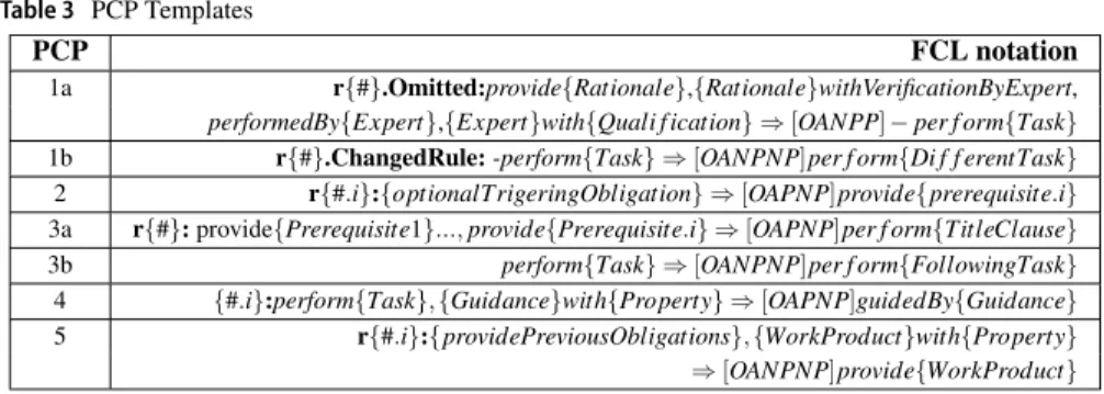
since the permission is not a violation of the obligation. Thus, the obligation does not persist after the permission is granted. In principle, all the requirements could be tailored. Thus, obligations are modeled as [OAPNP] or [OANPNP]. In this case, obligation and permission have contradictory conclusions, but the permission is superior since it represents an exception. Table 3 presents the templates of the PCPs. In all templates {#} should be replaced with the number that identifies the require-ment in the standard. When it is described as {#.i} , the i should be replaced by a, b, ..., n, where n is the number of sub-items, e.g., if there is a requirement with two parts that is identified with the number 5, the rules’ identifiers are 5.a and 5.b. Fol-lowing, we present a more detailed description of the patterns.
Tailoring requirements (PCP 1a and 1b) Tailoring means to adapt (omit or
per-form differently) the requirements to a specific project in a compliant per-form. Tailor-ing requires a rationale (or justification). For beTailor-ing valid, a rationale should always be verified by an expert. The rationale is an input element, and its verification is a property. An expert with specific qualifications should also be appointed. Thus, we use the templates for definitional and property-based propositions described in Fig 4 for in/output elements and roles, i.e., provide{Rationale} ,
{Rationale}with-VerificationByExpert, performedBy{Expert} and {Expert}with{Qualification} .
Pro-viding those four conditions permit to omit the requirement (in other words, per-mit not to perform the requirement). Any of the definitional and property-based propositions present in Fig. 4 could be the target of such omission. For explana-tions purposes, we consider omitting a requirement that imposes the definition of a task ( ⇒ [P] − perform{Task} ). In PCP 1a, {Rationale} should be replaced with the title of the required justification. {Task} should be replaced with the name of the task that will be omitted. Finally, {Expert} should be replaced with the role required and {Qualification} with the necessary qualifications. A second rule, i.e.,
PCP 1b, is included in case the task is done in a different way, where [OANPNP]
perform{DifferentTask} corresponds to the new task replacing the previous one. Provide a prerequisite (PCP 2) A prerequisite is an obligatory input element,
which should be fulfilled before it is in force (preemptive). PCP 2, {prerequisite} should be replaced with the name of the prerequisite. If a previous rule triggers the prerequisite, its conclusion is included in the {optionalTrigeringObligation} , e.g., when the prerequisite is produced by a previous task. Prerequisite could have prop-erties. In this case, the {optionalTrigeringObligation} could be a list of such proper-ties, using the template {Element}with{Property} . Otherwise, it is left empty.
Perform a unit of work (PCP 3a and 3b) Template PCP 3a represents the
perfor-mance of a unit of work that can be prescribed in a process (i.e., phase/activity/task). It considers the prerequisites, if any, as the conditions of the applicability of the rule, which normative conclusion is performing a unit of work (e.g., a phase). It could be preemptive ([OAPNP]), if the prerequisites and the task are provided at the same time. It can be non-preemtive ([OANPNP]) as in template 3b, if the prerequisite is another task, that have to be done first. In the example of PCP 3a, {TitleClause} should be replaced with the specific clause title.
Provide guidance (PCP 4) Guidance elements may not be required
dur-ing standards compliance auditdur-ing. However, internal policies in a company may impose guidance elements. In that case, guidance elements should be provided at the moment the element guided is created. We create the propositions by using the template for guidance provided in Fig. 4, i.e., guidedBy{Guidance} and {Guidance}
with{Property} . Guidance can be defined for any element in the process (tasks, work
product, tool, or role). For explanation purposes, we consider perform{Task} (see PCP 4).
Provide a work product (PCP 5) Work products are the result of certain
require-ments. Thus, these requirements are presented as antecedents that oblige the pro-vision of the related work product. PCP 5 presents this aspect in FCL, where {providePreviousObligations} should be replaced with the conditions that oblige the
work product’s production, usually the execution of a task (perform{Task} ). Work product properties may be also required, i.e., ( {WorkProduct}with{Property} , where {WorkProduct} should be replaced with the work product’s name and {Property}
with the corresponding property. Table 3 PCP Templates
2.6 ACCEPT
ACCEPT (Automatic Compliance Checking of Engineering Processes against sTandards) (Castellanos et al. 2018b, a), is a safety-centered planning-time frame-work aimed at facilitating the analysis of the tradeoffs associated with the planning of compliant processes in the safety-critical context. ACCEPT uses state-of-the-art tools and methodologies (see Fig. 5).
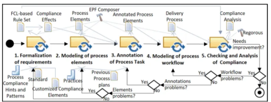
In particular, ACCEPT is based on compliance by design (Lu et al. 2007), a pre-ventive approach aimed at integrating compliance requirements into process plans. Such an approach requires the definition of two specifications. The first one is the FCL (recalled in Sect. 2.3) based standards requirements. FCL provides a framework that unambiguously represents the deontic notions required for compliance analysis. The second one is the process plan enriched with compliance effects, which is pro-vided via SPEM 2.0-like artifacts in EPF-C (recalled in Sect. 2.2). SPEM 2.0 is flex-ible, i.e., concepts can be customized and extended to permit not only the creation artifacts related to processes but also compliance checking artifacts, such as standard requirements, rules and annotated process plans. SPEM 2.0-like artifacts are also reusable since capabilities for modularization and extensibility are implemented in EPF-C (i.e., plugins). With the composition of EPF-C and the Base Variability Man-agement Tool (Javed and Gallina 2018b), tailoring of compliance artifacts and reuse is also facilitated. ACCEPT is equipped with guidance regarding process compli-ance hints and patterns (recalled in Sect. 2.5) that ease the creation of the required specifications. ACCEPT uses Regorous (recalled in Sect. 2.4), which provides a sound algorithm for the analysis of FCL rules that automatically check if a com-pliance-aware engineering process plan (CaEPP) is designed, i.e., if the elements set down by the requirements (e.g., tasks, personnel, work products, techniques, and tools, as well as their properties) are present at given points in the engineering pro-cess plan. The approach consists of five methodological steps, as shown in Fig. 6.
Step 1: Formalization of Requirements Standard requirements are formalized
in FCL by and trained person supported by a process engineer (or an FCL-trained process engineer). Three inputs are required: the standard requirements, the compliance hints and patterns guidance, and the EPF-C plugin with the customized compliance checking artifacts (see Fig. 4). First, the requirements should be clas-sified in terms of the process elements they target and their properties to create the rules’ propositions (see Sect. 2.5.1). Then, PCPs are used to create the FCL rules
(see sect. 2.5.2). The output is an EPF-C plugin with the FCL-based ruleset contain-ing information about the standard, their requirements, the rules derived from the requirements, and the separated set of propositions composing the rules.
Step 2: Modeling of Process Elements Capturing process plan elements is a task
performed by the process engineer. The required input is information about process plans, which could steam from the organization’s practices and previous process plans. The output is the representation of the process elements in EPF-C, as depicted in Fig. 2a. Detailed guidance regarding the creation of content elements in EPF-C is provided in Tuft (2010)).
Step 3: Annotation of Process Tasks The annotation process, which a process
engineer performs manually, consists of assigning the compliance effects to the ele-ments that fulfill them as presented in Fig. 7. For this, the compliance effects mod-eled in the FCL ruleset (created in step 1) and the process elements (created in step 2), or previous process plans, are the inputs of this step. The output is the annotated process elements in EPF-C.
Step 4: Modeling of Process Workflow The process engineer uses the
compli-ance annotated process elements resulting from step 3 to model the workflow (see Fig. 2c). The output is the delivery process in EPF-C, which contains the process plan checkable for compliance, i.e., the compliance state representation of the pro-cess plan.
Step 5: Checking and Analysis Checking and analyzing compliance is a task
per-formed by the process engineer. The required inputs are the FCL-based ruleset and the delivery process. The output is the compliance analysis, which contains informa-tion regarding the rules violated by the process, their reparainforma-tion policies, and the rules that were not activated during the compliance checking analysis. Such infor-mation is used to improve the process plans to be checked iteratively. Reasons for such improvements could be workflow problems (error in the placement of tasks), failure in the annotation process (errors in the assignment of the compliance effects), failure in the selection of process elements (e.g., missed elements), or FCL ruleset errors (not applicable rules due to tailoring or standards evolution).
3 Case study design
In this section, we present the essential details regarding the case study design.
3.1 Rationale for the case study
In the European context, space software production is often the result of industrial cooperation. Such cooperation is coordinated using the de-facto standard ECSS-E-ST-40C (recalled in Sect. 2.1.2). Such a standard provides requirements that help customers formulate their project-specific requirements by using the EARM matrix. Suppliers need to prepare their responses by using the ECM matrix, which will help them implement the work. ECSS-E-ST-40C is a process-related standard. Thus, the planning of software engineering processes in compliance with project-specific ECSS-E-ST-40C applicable requirements is mandatory during contractual agreements. Moreover, the tailoring decisions, i.e., A, M, D, and N, should be docu-mented. Thus, we wonder if the current status of the models produced by ACCEPT could support space manufacturers’ needs. For this, we perform a case study, accord-ing to the guidelines provided in Runeson et al. (2012). In particular, we consider the selected portion of ECSS-E-ST-40C requirements related to the software items’ design (recalled in Table 1). Our case study is descriptive (i.e., it portrays the current status of ACCEPT) and exploratory (i.e., it seeks future ACCEPT improvements). The data collected is qualitative involving models and their descriptions. The cri-teria used for the analysis is described in Ghanavati et al. (2008). In particular, we analyze the effort to model (needed to establish a model for managing compliance), the effort to comprehend (processes and standards models), the effort to document
compliance, (needed to verify whether process models comply with standards
mod-els), and the effort to manage evolution, (needed to find potential instances of non-compliance when standards change). Moreover, we take into account the level of
coverage for the model (which shows how much of the requirements and
engineer-ing processes can be modeled), the level of coverage for compliance documentation (which examines the level of success of the approach in terms of documenting the compliance), and the level of coverage for the evolution management (which exam-ines the approach’s success in handling the changes).
3.2 Goal and research questions of the case study
As presented in Sect. 3.1, we want to analyze ACCEPT in the context of space soft-ware engineering processes planning in compliance with ECSS-E-ST-40C. We have
also selected specific criteria, which essentially consider two variables: effort and coverage level. The effort, according to Steele (2020), is a variable that could be estimated during task performance in two ways: the actual effort (determined by task demands) and the perception of effort (relative to a subject’s capacity to recog-nize the effort). In this case study, our analysis is based on actual effort (from now on called effort) since, in theory, it can be used to determine the intent to complete a task a priori, independently of any conscious actor. The coverage level is analyzed considering how the models respond to the information that needs to be required by the ECSS-E-ST-40C framework, i.e., information regarding standards, process plans, and compliance (i.e., EARM and ECM matrices). Thus, our goal is to
quali-tatively analyze the current effort required to model a CaEPP in ACCEPT for software development processes in compliance with ECSS-E-ST-40C and the coverage level of such models. Based on this goal, we derive the following research
questions:
RQ1: How could we consider the effort required in designing a CaEPP with ACCEPT for software development? The answer of this question will be
supported by answering the following subquestions:
RQ1.1: How could we consider the effort required to create models? RQ1.2: How could we consider the effort required to comprehend the models?
RQ1.3: How could we consider the effort required to document compliance?
RQ1.4: How could we consider the effort required to manage evolution?
RQ2: How could we consider the coverage level of a CaEPP for software development created with ACCEPT? The answer of this question will be
supported by answering the following subquestions:
RQ2.1: How could we consider the coverage level of the models? RQ2.2: How could we consider the coverage level of the documentation? RQ2.3: How could we consider the coverage level of the evolution management?
3.3 Unit of analysis and method
To support our goal (defined in Sect. 3.2), we model a CaEPP for space software engineering processes. The standard requirements involved in our models are the ECSS-E-ST-40C, focus on software design (recalled in Sect. 2.1.2). In general, ECSS-E-ST-40C determines mission-critical requirements that have an inherent relationship with safety issues since a software failure could lead to mission loss that could have catastrophic consequences. Thus, such requirements belong to the safety-critical context. The portion selected provides a view to the general structure of such a standard, i.e., prescribes requirements that impose the presence of process elements that can be tailored in a process plan. Thus, we consider such a portion representative of the whole standard. The method selected for conducting the case study is described in the steps required for facilitating automated compliance check-ing of engineercheck-ing processes against standards (see Fig. 6). Such a method permits us to collect the data required for the analysis.
3.4 Validity of the study
Case studies in software engineering are conducted to increase knowledge and bringing change in the studied phenomenon (Runeson et al. 2012). Researchers must consider issues that may diminish the results’ trustworthiness by demonstrat-ing the extent to which the researchers’ subjectiveness does not bias the results. In this study, we consider a scheme of four aspects of validity in case studies in soft-ware engineering defined in Runeson et al. (2012). (1) Construct validity reflects the extent to which the research represents the theoretical concepts used in the study. (2) Internal validity is of concern when causal relations are examined. (3)
Exter-nal validity addresses the ability of the research to be generalized. (4) Reliability is
concerned with the extent to which the data and analysis are dependent on specific researchers. Addressing these four validity aspects is essential since it permits an accurate account of the research by selecting and using acceptable methodological practices that guarantee correct steps for collecting and analyzing the data. The con-crete ways in which we addressed the mentioned validity aspects are listed below.
Construct validity To avoid construct validity, we established a chain of evidence
by rigorously following our defined methodology (see Fig. 6), reporting the results consistently with such a methodology. However, designed methodologies may be biased. For mitigat-ing this aspect, we review our assumptions against theoretical foundations several times during several sessions to avoid over-simplifications that may confirm our preconceptions. We also got external reviews in previous phases of our work, as well as initial stages of this case study. We use such reviews to improve our methodology, its presentation, and the definition of the case study itself.
Internal validity The manual formalization of the FCL rules may imply a inter-nal validity threat, due to the possibility of typos in the syntax and inconsistencies in the rules statements. For mitigating this aspect, we instantiated the process compliance hints and pat-terns (see Sect. 2.5) and performed manual syntactic correc-tions of the FCL specification. In the future, we plan to develop tools for supporting the process of writing and verifying rules.
External validity We have performed an ACCEPT analysis on a limited portion
of a software process standard. It is a single case study, but it is not trivial. It shows dilemmas and design choices that are typi-cal in safety-related engineering process plans. In particular, ECSS-E-ST-40C determines mission-critical requirements that have an inherent relationship with safety issues since mission loss could lead to catastrophic consequences. Thus, they belong to the safety context. Moreover, the ECSS-E-ST-40C portion selected contains all the characteristics regarding process-based standards, i.e., the definition of work units, in/outputs, ele-ments properties, and other process-related eleele-ments such as guidance, which have the possibility to be tailored. Such char-acteristics are presented in whole standard. Thus, the selected requirements are representative and can be generalized to the complete ECSS-E-ST-40C standard. However, the outcome of this case study applies to a CaEPP for software development that respond to the mentioned characteristics. Additional chal-lenges may arise when analyzing standards beyond safety and software that also apply in the safety-critical context. Thus, to generalize our framework capabilities, we must carry out case studies beyond the ones we have already performed.
Reliability Reliability threats were mitigated by involving the research-ers in peer debriefing, i.e., iterative review of research artifacts (formalization of standard requirements, EPF-C models) during all the process.
4 Data collection
In this section, we collect the data required for the case study.
4.1 Formalization of ECSS‑E‑ST‑40C requirements
As described in Sect. 2.6, we classify the requirements in terms of the process elements and their properties (see Table 4), and create the rules’ propositions (see Fig. 8) based on process compliance hints (see Sect. 2.5.1).
The initial part of the ruleset defines the provision of requirements TSSC, AD, DJ, PDR, which are needed to start the activity described in Table 1. The PCP 2 is used to create the rules mandating the requirements (rules r5.5.2.a to r5.5.2.d) and PCP 3a to create the rule mandating the phase definition (rule r5.5.2) as follows:
We define a custom category in EFP-C (ECSS-E-ST-40C) to create the rule set. For each requirement, we nest a category. In each category, we nest the rule. We assign the compliance effect (the conclusion of the rule) to each rule (see Fig. 9). All requirements and rules are modeled in a similar way.
We use PCP 3b formalize the requirements that define the first task Detailed
design of each software component (see rule 5.5.2.1), which prerequisite is the
activity definition (see rule 5.5.2). Then, we use PCP 5 to define the expected item (ei), which is the work product of this task (see rule r5.5.2.1.ei). Then we used the PCP 4 to define the guidance (see rule r5.5.2.1.guide).
Requisite 5.5.2.2 is the definition of the task Development and documentation of the
software interfaces detailed design, which produces two expected items (ei) Eid and Iid. As two ei are created, we further identify the rules by adding a and b to the rules
(see rules r5.5.2.2.ei.a and r5.5.2.2.ei.b).
𝐫𝟓.𝟓.𝟐.𝐚 ∶⇒ [OAPNP]provideTSSC 𝐫𝟓.𝟓.𝟐.𝐛 ∶⇒ [OAPNP]provideAD 𝐫𝟓.𝟓.𝟐.𝐜 ∶⇒ [OAPNP]provideDJ 𝐫𝟓.𝟓.𝟐.𝐝 ∶⇒ [OAPNP]providePDR 𝐫𝟓.𝟓.𝟐 ∶ provideTSSC, provideAD, provideDJ, providePDR
⇒[OAPNP]performDesignOfTheSoftwareItems 𝐫𝟓.𝟓.𝟐.𝟏 ∶ performDesignOfTheSoftwareItems ⇒[OANPNP]performDetailedDesign 𝐫𝟓.𝟓.𝟐.𝟏.𝐞𝐢 ∶ performDetailedDesign ⇒ [OANPNP]provideScdd 𝐫𝟓.𝟓.𝟐.𝟏.𝐠𝐮𝐢𝐝𝐞 ∶ performDetailedDesign ⇒[OANPP]guidedByReq5 − 5 − 2 − 1
𝐫𝟓.𝟓.𝟐.𝟐 ∶ performDetailedDesign ⇒[OANPNP]performDevelopAndDocumentSwInterfacesDesign 𝐫𝟓.𝟓.𝟐.𝟐.𝐞𝐢.𝐚 ∶ performDevelopAndDocumentSwInterfacesDesign ⇒[OANPNP]provideEid 𝐫𝟓.𝟓.𝟐.𝟐.𝐞𝐢.𝐛 ∶ performDevelopAndDocumentSwInterfacesDesign ⇒[OANPNP]provideEid
Fig. 8 Rules propositions
Requisite 5.5.2.3 is the definition of the task Production of the detailed design model (see rule r5.5.2.3) and three items are expected (see rules r5.5.2.3.ei.a, r5.5.2.3.ei.b and r5.5.2.3.ei.c).
Requisite 5.5.2.4 is the definition of the task Software detail design method (see rule r5.5.2.4) and one item is expected (see rule r5.5.2.4.ei).
Requisite 5.5.2.5 is the definition of the task Detailed design of real–time software (see rule r5.5.2.5) and one item is expected . However, this expected item has several properties, which are included in the antecedent of the rule r5.5.2.5.ei. Additionally, guidance is defined for this task. So, we use PCP 4 to define the mandatory guidance (see rule r5.5.2.5.guide).
Requisite 5.5.2.6 is the definition of the task Utilization of description techniques
for the software behaviour (see rule r5.5.2.6) and one item is expected (see rule
r5.5.2.6.ei).
Requisite 5.5.2.7 is the definition of the task Determination of design method
con-sistency for real–time software (see rule r5.5.2.7) and one item is expected (see rule
r5.5.2.7.ei). 𝐫𝟓.𝟓.𝟐.𝟑 ∶ performDevelopAndDocumentSwInterfacesDesign ⇒[OANPNP]performProductionDetailedDesign 𝐫𝟓.𝟓.𝟐.𝟑.𝐞𝐢.𝐚 ∶ performProductionDetailedDesign ⇒ [OANPNP]provideSsdm 𝐫𝟓.𝟓.𝟐.𝟑.𝐞𝐢.𝐛 ∶ performProductionDetailedDesign ⇒ [OANPNP]provideSddm 𝐫𝟓.𝟓.𝟐.𝟑.𝐞𝐢.𝐜 ∶ performProductionDetailedDesign ⇒ [OANPNP]provideSbdm 𝐫𝟓.𝟓.𝟐.𝟒 ∶ performProductionDetailedDesign ⇒[OANPNP]performDescribeSwDetailDesignMethod 𝐫𝟓.𝟓.𝟐.𝐞𝐢 ∶ performProductionDetailedDesign ⇒ [OANPNP]provideSdm 𝐫𝟓.𝟓.𝟐.𝟓 ∶ performDescribeSwDetailDesignMethod ⇒[OANPNP]performDetailedRealTimeSw 𝐫𝟓.𝟓.𝟐.𝟓.𝐞𝐢 ∶ performDetailedRealTimeSw, R −tddmWithDynamicAllocationResources, R − tddmWithMutualExlcusionsMechanisms, R −tddmWithSynchronizationMechanisms, R − tddmWithTimingMechanisms ⇒ [OANPNP]provideR − tddm 𝐫𝟓.𝟓.𝟐.𝟓.𝐠𝐮𝐢𝐝𝐞 ∶ performDescribeSwDetailDesignMethod ⇒[OAPNP]guidedByReq5 − 5 − 2 − 5 𝐫𝟓.𝟓.𝟐.𝟔 ∶ performDetailedRealTimeSw ⇒[OANPNP]performDescribeTechniquesSwBehavior 𝐫𝟓.𝟓.𝟐.𝟔.𝐞𝐢 ∶ performDescribeTechniquesSwBehavior ⇒[OANPNP]provideSbdmt
Requisite 5.5.2.8 is the definition of the task Development and documentation of
the software user manual (see rule r5.5.2.8) and one item is expected (see rule
r5.5.2.8.ei).
Requisite 5.5.2.9 is the definition of the task Definition and documentation of the
software unit test requirements and plan (see rule r5.5.2.9). One item, with
sev-eral properties is expected (see rule r5.5.2.9.ei) as well as guidance (see rule r5.5.2.9.guide).
Finally, requisite 5.5.2.10 is the definition of the task Conducting a detailed design
review (see rule r5.5.2.10), Eight items are expected after this task (see rules
r5.5.2.10.ei.a to r5.5.2.10.ei.h). 𝐫𝟓.𝟓.𝟐.𝟕 ∶ performDescribeTechniquesSwBehavior ⇒[OANPNP]performDeterminationDesignMethodConsistencyRT 𝐫𝟓.𝟓.𝟐.𝟕.𝐞𝐢 ∶ performDeterminationDesignMethodConsistencyRT ⇒[OANPNP]provideCRtdm 𝐫𝟓.𝟓.𝟐.𝟖 ∶ performDeterminationDesignMethodConsistencyRT ⇒[OANPNP]performDocumentationSwUserManual 𝐫𝟓.𝟓.𝟐.𝟖.𝐞𝐢 ∶ performDocumentationSwUserManual ⇒[OANPNP]provideInitialSum 𝐫𝟓.𝟓.𝟐.𝟗 ∶ performDocumentationSwUserManual ⇒[OANPNP]performDefinitionSwUnitTestReq 𝐫𝟓.𝟓.𝟐.𝟗.𝐞𝐢 ∶ performDefinitionSwUnitTestReq, SutpWithControlProcedures, SutpWithResponsabilities, SutpWithSchedule, SutpWithTestCaseSpecification, SutpWithTestDesign, SutpWithTestingApproach ⇒[OANPNP]provideSutp 𝐫𝟓.𝟓.𝟐.𝟗.𝐠𝐮𝐢𝐝𝐞 ∶ performDocumentationSwUserManual ⇒[OAPNP]guidedByReq − 5 − 5 − 2 − 9
Requirements tailored as omitted (not applicable (D) in the ECSS Applicability Requirements Matrix (EARM)) can be formalized using PCP 1a. For example, it is defined that requirement 5.5.2.10, which is the definition of the task Conducting a
detailed design review is omitted (see rule r5.5.2.10.Ommited). If we do not perform
the review, their work products are also not required.
We use the PCP 1b, if the same task is defined in the EARM as applicable with modification (M), or new generated requirement (N). For illustration purpose, we consider that a simple review could be performed instead of the detailed review (see rule r5.5.2.10.ChangedRule).
Propositions used in rules r5.5.2.10.Ommited and r5.5.2.10.ChangedRule should be added to the list of rule propositions presented in Fig. 8.
4.2 Modeling of process elements
Initial process plan elements are extracted from the standard ECSS-E-ST-40C, specifically, the requirements presented in Table 1. The result is process elements depicted in Fig. 10, which contains work products, tasks and guidance artifacts.
𝐫𝟓.𝟓.𝟐.𝟏𝟎 ∶ performDefinitionSwUnitTestReq ⇒[OANPNP]performConductingDetailedDesignReview 𝐫𝟓.𝟓.𝟐.𝟏𝟎.𝐞𝐢.𝐚 ∶ performConductingDetailedDesignReview ⇒[OANPNP]provideDDF 𝐫𝟓.𝟓.𝟐.𝟏𝟎.𝐞𝐢.𝐛 ∶ performConductingDetailedDesignReview ⇒[OANPNP]provideSDD 𝐫𝟓.𝟓.𝟐.𝟏𝟎.𝐞𝐢.𝐜 ∶ performConductingDetailedDesignReview ⇒[OANPNP]provideCDR 𝐫𝟓.𝟓.𝟐.𝟏𝟎.𝐞𝐢.𝐝 ∶ performConductingDetailedDesignReview ⇒[OANPNP]provideTS 𝐫𝟓.𝟓.𝟐.𝟏𝟎.𝐞𝐢.𝐞 ∶ performConductingDetailedDesignReview ⇒[OANPNP]provideICD 𝐫𝟓.𝟓.𝟐.𝟏𝟎.𝐞𝐢.𝐟 ∶ performConductingDetailedDesignReview ⇒[OANPNP]provideSUM 𝐫𝟓.𝟓.𝟐.𝟏𝟎.𝐞𝐢.𝐠 ∶ performConductingDetailedDesignReview ⇒[OANPNP]provideDJF 𝐫𝟓.𝟓.𝟐.𝟏𝟎.𝐞𝐢.𝐡 ∶ performConductingDetailedDesignReview ⇒[OANPNP]provideSUITP 𝐫𝟓.𝟓.𝟐.𝟏𝟎.𝐎𝐦𝐦𝐢𝐭𝐞𝐝 ∶ provideJustificationNotPerformConductingDetailedDesignReview, JustificationNotPerformConductingDetailedDesignReviewWithVerificationByExpert, performedByAssesor, AsessorWithExperienceECSS − E − ST − 40 − C ⇒[P] − performConductingDetailedDesignReview 𝐫𝟓.𝟓.𝟐.𝟏𝟎.𝐎𝐦𝐦𝐢𝐭𝐞𝐝 > 𝐫𝟓.𝟓.𝟐.𝟏𝟎 𝐫𝟓.𝟓.𝟐.𝟏𝟎.𝐂𝐡𝐚𝐧𝐠𝐞𝐝𝐑𝐮𝐥𝐞 ∶ −performConductingDetailedDesignReview ⇒[OANPNP]performSimpleReview
4.3 Annotation of process tasks
A copy of the process elements defined in Sect. 4.2 (depicted in Fig. 10) is created in a new plugin, which we called ComplianceAnnotatedProcessPlan. These pro-cess elements are also extended to the original by using the content variability type
Extends. With this extension, we ensure that the information previously defined is
also included, such as the assignment of in/output or guidance to the tasks. Then, every process element is annotated with the compliance effect they produce by add-ing the guidance elements that contains the effect (see Fig. 11). The complete com-pliance annotation of process elements is presented in Table 5.
4.4 Modeling of process workflow
The tasks annotated in Sect. 4.3 are used to create the delivery process (see Fig. 12). Fig. 10 Process elements plugin
As depicted in Fig. 13, ACCEPT involves the modeling of four separated models, which are concretized in EPF Composer as plugins. The
ComplianceCheckingCus-tomization (highlighted in red in the figure) is provided in the method and the
pro-cess engineer only needs to use it.
4.5 Checking and analysis of compliance
The ruleset formalized in Sect. 4.1, and the workflow modeled in Sect. 4.4 (located in the plugins ECSS-E-ST-40C-Requirements and
ComplianceAnnotatedProcess-Plan in Fig. 13, respectively) are the two specifications required by Regorous (recalled in Sect. 2.4) to perform automatic compliance checking. The results of the checking are presented in Fig. 14.
As Fig. 14a depicts, the process is non-compliant. Thus, the plan needs improve-ment. Such results could point to compliance problems on the workflow, in the anno-tation process, or missing characteristics in the process plans (e.g., absent tasks or work products). The problems related to the rules (e.g., wrong formalization) need to be analyzed in the context of specific standard with experts, such as safety asses-sors. For example, there is a violation regarding provideAD (see Fig. 14b). It turns out that rule r5.5.2.b is violated (see Fig. 14c). The reparation policy suggests to
prevent the violation, by performing provideAD after ’Start’. This means that in the
first task, which is called detailed design of each software component, we need to add the input AD and its corresponding compliance effect provideAD (see Fig. 14d). When the compliance checking results are positive, namely the result is the process
is compliant, it does not mean that there is no further improvement. Instead, we need
to perform the analysis, taking into account the rules that did not fire. Once the pro-cess is improved for compliance, compliance checking is performed iteratively until the process plan is deemed compliant by Regorous.
5 Case study analysis
In this section, we analyse the case study results presented in Sect. 4 by answer-ing the research questions defined in Sect. 3.2.
5.1 Effort designing a CAEPP for software development (RQ1)
We judge the effort determined by task demand, which is based on design choices. In theory, such effort can be used to determine the intent to complete a task inde-pendently of any conscious actor. We refer in this analysis to the effort required to create and comprehend the models and document and manage evolution.
5.1.1 Effort required to create the models (RQ1.1)
When using ACCEPT for creating a CaEPP for software projects, three models (the
ComplianceCheckingCustomization is provided in the method), which are
concre-tized in EPF-C as plugins, are required (see Fig 13). To populate the
ECSS-E-ST-40C-Requirements plugin, we needed to formalize requirements in FCL. Performing
a formalization process is, in general, a difficult task that requires skills, which can-not be taken for granted. Moreover, due to the sheer size of the standards, this work requires time and focus. An advantage of FCL is that it provides a valid set of under-standable concepts to the users of the standards, i.e., obligations, prohibitions, and permission (see Sect. 2.3). Moreover, ACCEPT provides process compliance hints and patterns (recalled in Sect. 2.5), which facilitate the identification and modeling of compliance artifacts, i.e., requirements and their corresponding rules as well as compliance effects (see Sect. 4.1). However, the instantiation of hints and patterns is done manually in a process that is repetitive and prone-to-error. Defining the
Pro-cessElements plugin required in a process is a task that is not difficult to perform
Table 5 Compliance effects annotation on process elements
Process element Compliance Effect
Detailed design of each software component performDetailedDesign
Scdd provideScdd
Development/documentation of the software interfaces performDevelopAndDocumentSwInterfacesDesign
Eid provideEid
Iid provideIid
Production of the detailed design model performProductionDetailedDesign
Ssdm provideSsdm
Sddm provideSddm
Sbdm provideSbdm
Define Software detail design method performDescribeSwDetailDesignMethod
Sdm provideSdm
Detailed design of real-time software performDetailedRealTimeSw
R-tddm provideR-tddm
Utilization of description techniques for the software performDescribeTechniquesSwBehavior
Sbdmt provideSbdmt
Determination of design method consistency for realtime performDeterminationDesignMethodConsistencyRT
CRtdm provideCRtdm
Development and documentation of the software user
manual performDocumentationSwUserManual
Sum provideInitialSum
Definition and documentation of the software unit test
re-quirements and plan performDefinitionSwUnitTestReq
Sutp provideSutp
Conducting a detailed design review performConductingDetailedDesignReview Req-5.5.2.1 Detailed design of each software component
Software components design guidedByReq5-5-2-1 Req-5.5.2.5 for the Detailed design of real–time software guidedByReq5-5-2-5 Req.-5.5.2.9 Definition and documentation of the
since EPF-C has graphical representations of the elements that can be modeled in a well-defined structure (see Sect. 4.2). However, a specific effort in terms of time is also required. ACCEPT states that the elements required in the
ComplianceAnnotat-edProcessPlan plugin are linked to the elements in other models in two ways (see
Fig. 12 Delivery process
Fig. 13 EPF-C plugins
Sect. 4.3). (1) By performing extensions between elements in the method content, to inherit the characteristics of the process elements. (2) By performing the compliance annotation process, which is the method that guarantees that the model is checkable for compliance. Currently, compliance annotations are performed manually, based on the domain expert’s knowledge about the engineering process.
In summary, there is a need to manually (and iteratively) formalize requirements, graphically model compliance and process artifacts, and extend and annotate com-pliance effects. Thus, the effort required to create models is significant and may increase with the continued attempting to do the same tasks repeatedly. However, the effort required to model the ECSS-E-ST-40C-Requirements plugin is only sig-nificant during the first time. The reason is that such a model can be used several times in different CaEPPs that are modeled in compliance with the same standard (until new versions of the standard are released). Similar situations could occur with the other plugins, but they need to be evaluated in project-specific circumstances.
5.1.2 Effort required to comprehend processes and standards models (RQ1.2)
The method uses artifacts that are systematically organized in a hierarchical and visual structure that permits the identification of compliance information. In par-ticular, standard requirements and their elements are arranged in a nested list of compliance artifacts (see Fig. 9a). Moreover, process elements are created in par-ticular structures that differentiate, e.g., work products from tasks (see Fig. 10). The abstract association of elements within process tasks (depicted in Fig. 2b) permits the comprehension of the required compliance information provided by the compliance effects. This abstraction provides an approach for direct require-ments allocation into process models. Thus, once the models are created, there is a required low effort to comprehend the information they contain. In summary, the models created in EPF-C have a specific structure that facilitates the visuali-zation of their artifacts and their use, proving models that have an advantage over, e.g., text-based approaches.
5.1.3 Effort required to document compliance (RQ1.3)
The ability to provide means to document method content and processes in SPEM 2.0-like elements was exploited in ACCEPT. Having an structural, hier-archical representation of the standards (see Fig. 9a) with descriptive informa-tion (see (see Fig. 9b), as well as content elements organized according to their function (see Fig. 10) helps to have a written record of the artifacts required for compliance. This structural representation, originally provided by SPEM 2.0, may facilitate the work of a third party (independent) assessor in case the par-ties decide to include additional certainty to their assessment schema. Thus, the required high modeling effort results in lower compliance documentation effort.
5.1.4 Effort required to manage evolution (RQ1.4)
The compliance information in ACCEPT created in Sect. 4.1 could be seen as an initial frozen specification of the standard. However, such specification does not need to be bypassed altogether, when obsolescence no longer stands the strain of being frozen, i.e., a new version of the standard is released. In normal condi-tions, only some requirements change, and some get deprecated, but the majority remain. For example, the ECSS-E-ST-40-C has a log, which explicitly describes few adjustments regarding previous versions (ECSS-E-40 Part 1B, released on 28 November 2003, and the ECSS-E-40 Part 2B, released on 31 March 2005). In ACCEPT, such changes can be embraced. First, as specifications are reusable, a copy of the requirements can be performed and saved with the new version name. Second, as the requirements model is hierarchically designed, the changes can be absorbed in an orderly way. Once a new version of the standards is defined, changes in the rules may impact the compliance status. Thus, it becomes neces-sary to re-check the process plans. However, as the rulesets are executable, the checking is easier, and process plans can be improved according to the new ver-sion of the ruleset (as described in Sect. 4.5). However, standards evolution would require some human intervention. In particular, there is a need for monitoring the changes in the standards and maintain accuracy in the rulesets. EFP-C provides textual descriptions regarding, i.e., versioning or revisions, which can be used to maintain a log of information between users facilitating further revision work.
5.2 Coverage level of a CaEPP for software development (RQ2)
We judge the models’ coverage level, taking into account how the information provided by the CaEPP models fit in the information required by the ECSS-E-ST-40C framework. We refer to the coverage level of the models, the compliance documentation, and the evolution management.
5.2.1 Level of coverage of the models (RQ2.1)
The models used in ACCEPT cover several aspects required in process compli-ance. First, standard artifacts (see Fig. 9a) are represented by a structure that cov-ers the textual description of the requirements, their respective FCL rules, and compliance effects. Second, the method content provided (see Fig. 10) covers the elements required to describe detailed process plans. Third, the compliance effects annotation (see Fig. 11) covers the requirements allocating into process plans, which permits us to understand the explicit relationships between artifacts. Finally, the compliance analysis provided by Regorous (see Fig. 14) covers the compliance status of the process plan, the compliance violations, and possible resolutions that facilitate the compliance analysis.