School of Innovation, Design and Engineering
Pre-study on the use of additive
manufacturing to produce low
volume complex parts and its
environmental sustainability
A Case Study at Volvo CE
Master thesis work
30 credits, Advanced level
Product and process development Production and Logistics
Aldric Sreedhar, Kaushik Gupta C.L.
2020
Report code: xxxx Commissioned by:
Tutor(company): Johannes Kautto Tutor(university): Yuji Yamamoto Examiner: Antti Salonen
ABSTRACT
With the rapid increase in demand for more high-value customized products and a more sustainable approach to manufacturing, companies are focusing on being more flexible while also trying to minimize environmental impact. As it is not possible to meet these current demands using traditional manufacturing techniques, manufacturing industries are searching for better manufacturing alternatives to address these issues in order to stay competitive. In this thesis, the two issues of manufacturing complex, low volume parts and environmental sustainability were investigated with the use of the additive manufacturing (AM) technology and possible improvements/recommendations were suggested. The conclusions drawn suggested that AM could be used to produce complex parts more efficiently and also proved to be a more sustainable alternative with decreased energy and resource consumption when compared to traditional methods.
Keywords: Methods of AM, AM materials, review of AM, design for AM, metal AM, plastic
AM, applications of AM, sustainability of AM, sustainable additive manufacturing (SAM), hazards of AM and reliability of AM.
ACKNOWLEDGEMENTS
I take this opportunity to express our appreciation to all the wonderful people who were all the part of our thesis.
Firstly, we thank Yuji Yamamoto, our supervisor at MDH, for his support and his advises during this thesis and Johannes Kautto, our supervisor at Volvo CE for providing this opportunity to us and for guiding us in all possible ways to carry out this thesis.
Secondly, I would like to thank Andersson Magnus, Ulf Gustavsson, Stefan Karlsson and personnel working in the low volume department. Special thanks to Ulrik Beste from VBN in supporting us and answering all our queries.
Aldric Sreedhar Kaushik Gupta C L Eskilstuna, 2020.
Contents
1. INTRODUCTION ... 1
1.1. Background ... 1
1.2. Problem formulation ... 2
1.3. Aim and Research questions ... 2
1.4. Project Limitations ... 3
2. RESEARCH METHOD ... 4
2.1. Quantitative and qualitative methods ... 4
2.2 Case Study ... 5
2.3 Case company and case description ... 5
2.4. Research Process ... 6 2.5. Data collection ... 7 2.5.1. Literature Review ... 8 2.5.2 Structured Interviews ... 9 2.6. Quality of research: ... 9 2.7. Data Analysis ... 10 3. LITERATURE REVIEW ... 12
3.1. Additive manufacturing processes... 12
3.1.1. Fusion deposition modelling (FDM) ... 12
3.1.2. Powder bed fusion ... 13
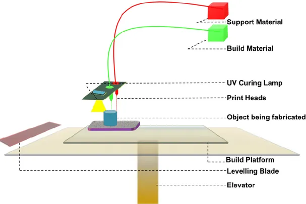
3.1.3. Inkjet printing ... 15
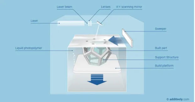
3.1.4. Stereolithography ... 16
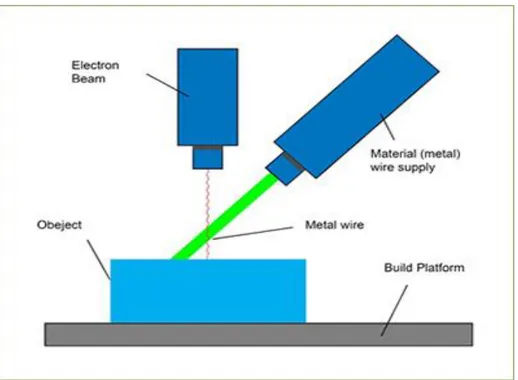
3.1.5. Direct energy deposition ... 17
3.1.6. Laminated object manufacturing ... 19
3.2. Materials ... 20
3.2.1. Metals and alloys ... 20
3.2.2. Polymers and composites ... 24
3.3. Need for DFAM ... 26
3.3.1. Design for additive manufacturing (DFAM) ... 27
3.4. Comparison of AM and CM ... 29
3.4.1. Flexibility in design ... 29
3.4.2. Cost of geometric complexity ... 30
3.4.3. Dimensional accuracy ... 30
3.4.5. Material and resource efficiency ... 30
3.4.6. High volume production: ... 31
3.4.7. Low volume production ... 31
3.5. Need for research into additive manufacturing with respect to environmental sustainability 31 3.5.1. AM’s impact on environmental sustainability ... 32
3.5.2. Challenges and limitations ... 34
3.5.3. Potential improvements for optimizing the AM system design ... 35
3.6. Health and safety issues associated with AM ... 36
3.6.1. Identified safety concerns with each AM process ... 37
3.6.2. Other possible safety and health related challenges associated with AM that need to be addressed ... 39
4. EMPIRICAL FINDINGS ... 41
4.1. Volvo CE (Case company) ... 41
4.1.1. Current use of AM in Volvo CE ... 41
4.2. VBN Components (Suppliers to Volvo CE) ... 41
4.1.1. Current use of AM in VBN ... 42
4.3. Interview findings based on research questions ... 42
4.3.1. Impact of AM in production of complex parts ... 42
4.3.2. Impact of AM with respect to environmental sustainability and safety ... 44
4.3.3. Possible challenges involved with AM ... 44
5. ANALYSIS ... 46
5.1. Complex parts with AM ... 46
5.1.1. Benefits over CM ... 46
5.1.2. Identified AM processes suitable for producing complex parts ... 48
5.1.3. Challenges and limitations with the use of AM ... 48
5.2. Environmental sustainability with AM ... 49
5.2.1. Benefits over CM ... 50
5.2.2. Challenges and limitations with the use of AM ... 51
5.2.3. Suggestions for improvements/process optimization ... 53
6. CONCLUSIONS AND RECOMMENDATIONS ... 54
7. REFERENCES ... 57
List of Figures
Figure 2- 1: Visual representation of research process ... 7
Figure 3-1: Schematic representation of Fusion deposition modelling (additively.com) ... 13
Figure 3-2: Schematic representation of Powder bed fusion (lboro.ac.uk) ... 15
Figure 3-3: Schematic representation of Inkjet printing (researchgate.net) ... 16
Figure 3-4: Schematic representation of Stereolithography (additively.com) ... 17
Figure 3-5: Schematic representation of Direct energy deposition (lboro.ac.uk) ... 18
Figure 3-6: Schematic representation of Laminated object manufacturing (Gibson, Rosen & Stucker, 2015) ... 20
Figure 3- 7: Schematic representation of AM process without DFAM (Ponche, Kerbrat, Mognol and Hascoet, 2014) ... 28
Figure 3- 8: Schematic representation of AM process with DFAM (Ponche, Kerbrat, Mognol and Hascoet, 2014) ... 29
List of Tables
Table 2- 1: Data collection methods ... 8Table 5- 1: Summary of AM processes with advantages and disadvantages ... 49
Table 5- 2: Summary of advantages and limitations of using AM with regards to environmental sustainability ... 53
List of Abbreviations
AM Additive manufacturing CAD Computer aided design SLA Stereolithography
ATSM American society for testing materials 3DP 3-dimentional printing
SLM Selective laser melting EBM Electron beam melting SLS Selective laser sintering
DMM Droplet based metal manufacturing FDM Fused deposition modelling
DED Direct energy deposition
LOM Laminated object manufacturing LSF Laser solid forming
DMD Direct metal deposition LENS Laser engineered net shaping DLF Directed light fabrication
EBAM Electron beam additive manufacturing WAAM Wire + arc additive manufacturing UAM Ultrasonic additive manufacturing CNC Computer numerical controlled FGM Functionally graded material PC Polycarbonates
PLA Polylactic acids
ABS Acrylonitrile butadiene styrene VGCF Vapor-grown carbon fibre
DFAM Design for additive manufacturing SAM Sustainable additive manufacturing CM Conventional manufacturing
UFPs Ultra-fine particles LCA Life cycle assessment
VOCs Volatile organic compounds ENMs Engineered nano materials PBF Powder bed fusion
TTM Time to market
1
1. INTRODUCTION
This section presents the background, problem definition and purpose of this thesis. Two research questions are formulated in relation to the background and problem. Finally, the scope of this thesis is defined, which sets the limitations of this research.
1.1. Background
In today’s global market there is an increase in demand for more customized products, while there is a constant shrink in the product lifecycle and an increase in customer awareness. This has created a great uncertainty in the market demand (Sisca, Fiasché & Taisch, 2015). For companies to stay competitive, products need to be designed keeping two main objectives in mind: reduction in time and cost; increase in quality and flexibility (Sheng, Tang & Zhao, 2015). Industries are therefore required to produce in lower volumes, focusing on higher added value and sustainability along with a high level of innovation (Thymianidis et al. 2013). Customer demand is progressing in a way such that they are looking for other secondary services to be offered which are centred around the primary manufactured products themselves (Sisca, Fiasché & Taisch, 2015). These current demands cannot be effectively achieved using old manufacturing techniques and business models, which are pushing industries towards much needed transformation (Sisca, Fiasché & Taisch, 2015). This has brought upon the need for additive manufacturing (AM) technologies, which has the potential of transforming the current manufacturing industry.
AM is a technique that is used for producing a wide range of products with complex geometries, using data derived from a 3D computer-aided-design (CAD) model (Tuan et al. 2018). AM involves various manufacturing techniques with a similar principle of creating products by adding or stacking layers of materials without the need of special tooling, deriving the data directly from CAD models (Gibson, Rosen & Stucker, 2009). This technology, also known as stereolithography (SLA) was developed in 1986 by Charles Hull, which subsequently lead to developments such as fused deposition modelling, powder bed fusion, inkjet printing and contour crafting (Tuan et al. 2018). According to the American Society for Testing Materials (ASTM) AM is defined as “a process of joining materials to make objects from 3D model data, usually layer upon layer, as opposed to subtractive manufacturing methodologies” with synonyms such as additive fabrication, additive process, additive techniques, layer manufacturing, additive layer manufacturing, 3D printing and freeform fabrication (Frazier, 2014). Rapid prototyping and tooling were one of the very first applications of AM (Guo & Leu, 2013), with new applications emerging as AM methods and materials are constantly being developed, which in-turn has the ability/potential to transform manufacturing and logistics processes (Tuan et al. 2018). AM was initially used by architects and designers to create functional prototypes due to its capability of producing rapid and cost-effective prototypes (Berman, 2012). Currently AM has been widely applied in various fields such as construction, biomedical, aerospace etc. One of the reasons for the development of AM technologies in the recent years has been due to the expiry of earlier patents, which has made the technology more accessible to manufacturers (Berman, 2012). AM has given manufacturers a tool to tackle the challenge of product customization, which involves high manufacturing costs. AM has the
2
ability of producing a wide range of customized, low volume products with complex geometries for relatively lower costs (Berman, 2012). AM is also advantageous with respect to utilization of material, freedom of design and therefore greater flexibility in design when compared to traditional manufacturing practices which involve subtraction of material and lesser freedom of design (Sisca, Fiasché & Taisch, 2015). This allows for a quick changeover between designs without almost negligible costs and setup times. AM also includes a wide variety of materials which includes polymers, ceramics, concrete and metals. AM also allows the use of two or more different materials to create composites, which further broadens the scope of AM (Tuan et al. 2018).
Along with the numerous advantages of AM there are also certain drawbacks associated with the use of this technology. Although AM has the capability of manufacturing parts of various sizes, ranging from the micro to macro scale, the precision of these parts is largely dependent on the method employed and the scale at which they are manufactured. 3D printed parts tend to show inferior mechanical properties and are hindered by their anisotropic behaviour. Therefore, an optimized 3D printing pattern must be followed choosing the right orientation to minimize such flaws. 3D printing is also sensitive to the environment of printing, which may influence the quality of the final printed product (Ivanova, Williams & Campbell, 2013). The high costs and longer processing times are some of the main challenges faced while using 3D printing (Tuan et al. 2018).
Therefore, it is important to study and understand the advantages and disadvantages of the various AM techniques to see which method can be used over the traditional manufacturing methods, in order to attain a true competitive edge.
1.2. Problem formulation
As there is an increase in the demand of more customized, complex products/prototypes it is necessary for manufacturing industries to be more flexible and hence more capable of producing products on demand according to customer specifications/requirements. As seen in the section above, this change in market demand cannot be addressed effectively with the existing traditional manufacturing systems as it is not feasible to manufacture such products with traditional manufacturing, in an environmentally sustainable manner. Therefore, there is a need for a more flexible, environmentally sustainable production system that can be able to manufacture products/prototypes on demand, that are tailored to meet the customer requirements, with minimum cost and time spent while also being eco-friendly. As AM can be used to manufacture a wide range of products with complex geometries, it is necessary to identify the most suitable AM method and how it can be beneficial over a conventional manufacturing system in terms of productivity and sustainability.
1.3.Aim and Research questions
The aim of this thesis is to understand how the use of AM can be beneficial over conventional systems for the purpose of manufacturing low volume, complex products/prototypes and to
3
also understand the impact AM has on the environment and sustainability in comparison with conventional methods, while manufacturing these low volume, complex products/prototypes. In order to fulfil this objective, the following research questions need to be answered:
Research question 1. How is it beneficial to use additive manufacturing in low volume/prototype department over conventional methods, in producing complex parts?
Research question 2. How does AM impact the environment and sustainability in comparison with conventional methods?
1.4.Project Limitations
Following are the limitations faced while conducting this thesis:
• This thesis is limited to literature review and empirical data from interviews due to restricted access to quantitative data because of proprietary issues.
• Lack of research material relevant to the area of study as additive manufacturing is a rather new technology.
• As this thesis is a pre-study it does not involve an in-dept comparison between AM and CM.
4
2. RESEARCH METHOD
This chapter describes the research methodology. It includes the choice of case study along with a description of the case and the case company.The research process is also illustrated visually which is followed by a description of how data was collected. Furthermore, the chapter also presents how quality of research is ensured.
2.1. Quantitative and qualitative methods
Qualitative and quantitative methods of study have long been two major methodologies of study among academia. Qualitative research is a tool by which the meaning given to a social or human problem by individuals or groups can be understood. The study involves the process of new questions and methods, the gathering of data usually in the participant’s environments, inductive interpretation of information going from specifics to general themes and the researcher’s interpretation of the data. (Creswell, 2009).
The way in which the data is treated is the most important difference (Brannen, 1992). In quantitative approach a researcher carries out his study by testing of theory is carried out by specifying and narrowing down a hypothesis and also by the collection of data that supports the hypotheses (Creswell, 2009). In quantitative approach, the researcher also defines and isolates variables and its categories, later these variables are linked together in order to frame hypotheses before the data is even collected, and are then tested upon the data (Brannen, 1992) whereas the researcher begins with defining the general concepts in qualitative research which changes later in their definition as the research progresses. For quantitative approach, the variables are the required tools and means of the analysis and on the other hand for the qualitative approach they are the product or outcome of the research (Brannen, 1992). The qualitative research involves looking for patterns of inter relationship between the sets of concepts that are usually unspecified through a wide lens whereas in quantitative research, the researcher looks at a set of specified variables through a narrow lens (Brannen, 1992).
The second important difference between the two approaches is in the way they collect data. In qualitative approach the three main kinds of collection of data involves in depth, open-ended interviews, direct observation and written documents whereas quantitative approach includes structured interviews, standardized tests, experiments and the use of questionnaires (Johansson, 1995).
Because of the ability to approach the field work not limited by predefined analytical categories, the qualitative approach results in in depth and detail studies of selected issues. Quantitative approach on the other hand involves the use of structured approaches in order to fit the broad range of people’s viewpoints and experiences into a limited number of predetermined categories of answer (Johansson, 1995).
Since this case study involves a pre-study which will be conducted by using literature research and empirical data from interviews and observations, the qualitative approach is best suited for this particular case.
5
2.2 Case Study
A case study involves a comprehensive study by carefully observing a unit, which may be an individual, a community, an institution, or a situation. It involves studying a particular unit in depth such that each and every aspect can be observed and studied in a detailed manner after which suitable conclusions can be drawn (Kothari, 1990). Case study method, when applied in the right manner can be a very effective method in researching science, assessing programs, and developing theories or hypotheses (Baxter & Jack, 2008).
“The case study method explores a real-life, contemporary bounded system (a case) or multiple bounded systems (cases) over time, through detailed, in-depth data collection involving multiple sources of information… and reports a case description and case themes”. (Creswell,
2013, p. 97).
Researchers must consider if it is required to do a single case study or a multiple case study. A multiple case study is required when the case involves more than one single case, where the researcher is trying to understand the interlinks (similarities and differences) between multiple single cases, thereby analysing data through all cases instead of just analysing data within an individual case (Yin, 2003). Although multiple case studies create a more convincing case with more empirical evidence to back up the theory, it can be highly expensive and very time consuming (Eisenhardt & Graebner, 2007; Baxter & Jack, 2008). A single case study is the most suitable choice for a researcher if the unit to be analysed is one single thing ( for example a specific person from a specific group or a specific group as a whole) (Yin, 2003). Since this particular case involves a single case, which is to research the benefits of using additive manufacturing over conventional methods in the production on complex parts/prototypes, also considering environmental sustainability factors, the method used will be that of a single case study method. Also due to time constraints and other limitations, single case study method is the most suitable one for this particular study.
A case study also involves various methods for collecting data which may include both qualitative methods such as observations, analysing different documents etc and quantitative methods such as questionnaires, structured interviews etc. (Zahle, 2018). When multiple data sources are used, it allows for an increase in data reliability and data quality, wherein consistent data from multiple data sources can be used to provide a stronger argument (Stake, 2010).
2.3 Case company and case description
This case study was conducted at Volvo Construction equipment (Volvo CE). Volvo CE is a major international company that develops, manufactures and markets equipment for construction and related industries. They offer a broad range of products along with an efficient worldwide service and a range of customer solutions in, for example, financing and used equipment. With over 14,000 employees, Volvo CE is one of the largest companies in the industry. Their wide range of products and services are offered in more than 140 countries through their global distribution network (Volvo CE, 2020).
6
The plant in Eskilstuna was established in 1832 by Theofron Munktell. First a mechanical workshop, the site was later converted into a tractor factory before finally becoming one of the largest machine processing plants in Europe. The plant is specialized in the production of components with transmissions and axels of excavators, wheel loaders and articulated haulers. On top of that, Volvo CE Eskilstuna is also home to functions like Technology, Sales & Marketing, IT and Purchasing, employing in total over 2,100 people (Volvo CE, 2020). By classifying manufacturing regions under the three key attributes; customization, volume and complexity-advantage, we can identify the specific manufacturing areas, which makes it easier to identify the trade-offs between AM and conventional methods in the required area. There are also certain factors to be considered such as complexity of the part, cost, material used, time, energy consumption, sustainability and environmental factors etc. before the method of manufacturing can be selected (Silveira, Borenstein, & Fogliatto, 2001). Since there in an increased demand for highly customized, low volume complex products/prototypes, the manufacturing area that needs to be researched is that of same.
This case study is conducted at the Volvo CE plant in Eskilstuna, in the low volume/prototyping department. The case involves investigating the scope of implementing the additive manufacturing (AM) technology as an alternative to the existing conventional machines currently being used at the department. The scope of this case is further narrowed down to the production of complex parts/prototypes such that a comparison can be drawn between additive manufacturing and conventional methods to see which method of manufacturing is more viable in terms of cost, time, and environmental sustainability. Therefore, the various AM methods are investigated to choose the best possible AM method that could be implemented at the low volume/prototype department.
2.4. Research Process
The research process which involves several steps as shown in the figure2-1 below, begun with first identifying the area of research by communicating with the company and analysing the work environment i.e., the low volume/prototyping department. After the area of research was identified and the aim and scope of this thesis were fixed, the research questions were then established. Thereafter, relevant scientific material was collected and read through to get a general understanding of the area of research and also to find specific information relevant to the research question. Data was then collected through multiple structured interviews at both Volvo CE (case company) and VBN (supplier to Volvo CE that manufactures using AM). Additional data in the form of some information that both Volvo CE and VBN currently have on AM was also collected. This data was then analysed by connecting data from literature and empirical findings, to give a comparison between both the manufacturing methods. Conclusion were then drawn from the analysis and important/relevant findings were presented accordingly.
7 Figure 2- 1: Visual representation of research process
2.5. Data collection
There are multiple data collection methods that are included in the case study research method that involve qualitative methods such as literature, qualitative interviews and researcher observation (Gerring, 2006). The data collection techniques used in this thesis are mainly through literature, interviews, observations and multiple meetings with the company where certain points regarding the study were discussed. Data collection methods used in this thesis are shown below in table 2-1.
8
Method Type Description
Observations Qualitative Observations made and noted down by observing the low volume department and communicating with shop floor workers to identify potential areas where AM can be implemented.
Literature Qualitative Scientific material collected in the form of scientific papers, journals, articles and books.
Interviews Qualitative Interviews conducted with relevant employees from Volvo and VBN. Data was collected on conventional methods (Volvo) and additive manufacturing (Volvo & VBN).
Table 2- 1: Data collection methods
2.5.1. Literature Review
A literature review involves the systematic collection of existing research which is then carefully reviewed and synthesized (Tranfield, Denyer, & Smart, 2003). Irrespective of the discipline, literature review is considered to be one of the building blocks of any type of academic research and is therefore considered as a priority for all academics. By reviewing literature and synthesizing various findings, stronger evidence can be presented and certain areas can be identified where further research is required (Snyder, 2019).
Various literature in the form of research papers, research journals, books, theses etc. has been reviewed on topics such as methods of additive manufacturing, materials associated with additive manufacturing, design for additive manufacturing, sustainability factor of additive manufacturing, safety factor of additive manufacturing etc.
The scientific material collected for this research was obtained from various scientific databases such as Scopus, IEEE Xplore, ScienceDirect, Emerald Insight and Google Scholar, using keywords such as methods of AM, AM materials, review of AM, design for AM, prototyping, metal AM, plastic AM, applications of AM, flexible manufacturing, progress of AM, sustainability of AM and reliability of AM. The selected articles were identified and collected based on relevance to the research topic and keywords used. The advanced search option was then used to filter down these searches to provide research material within the last 30 years. Further relevant research material was collected using the snowball technique. The collected papers were then filtered and categorized under subcategories such as methods, materials, sustainability etc. by reading through abstracts.
9
2.5.2 Structured Interviews
As the name structured interviews suggests the collection of required data is carried out in a structured way. Highly standardized techniques for the purpose of recording and a set of predetermined questions are involved in such interviews and hence the interviewer in this method always follows a rigid procedure, asking the questions that are predetermined questions in a prescribed order. On the other hand, unstructured interviews do not have a system with all the pre-determined questions and standardized techniques for the purpose of recording the information to follow. A much greater freedom is given to the interviewer when conducting a non-structured interview to ask supplementary questions, to omit certain questions and also to change the sequence depending on the way the interview takes place and, on the information, collected. But flexibility of this kind results in lack of comparability of the one with another and this also makes it difficult and time consuming in order to carry out the analysis by interpreting the data collected compared to the structured interviews. It takes a lot of skill and also more in-depth knowledge for the interviewer to conduct unstructured interviews and are used in case of exploratory or formulative research studies. Often structured interviews are chosen in case of descriptive studies as it is economical and will provide a safe basis for generalization and also this type of interviews can be conducted by the interviewer with lesser skill compared to the unstructured interviews.
2.6. Quality of research:
According to (Yin, 2009), there are four dimensions of research quality, Construct validity, internal validity, external validity and reliability and according to (Karlsson, 2009, Merriam, 2009) Validity, reliability and ethics are the important aspects in order to evaluate the quality of any research. It is the validity and reliability on which the quality of the research is measured, and it is the potential of the researcher to carry out the project on which the validity and reliability of the research depends. It should be very specific and should be reasonable or likely for the readers to be able to judge the conclusions that are drawn for it to be a qualitative research. (Merriam, 1998).
By conducting interviews in Volvo and VBN based on the literature review, which is supported by the additional knowledge gathered by the author by making real time on-site observation the internal validity of this research is strengthened (Åhlström and Karlsson, 2009). Further this is increased by using triangulation between the sources of collection of the data like interviews, observations, process categorization by which it becomes easier to judge the conclusions, also by allowing supervisors to read and comment on the findings (Merriam, 2009, Åhlström and Karlsson, 2009).
By aiming for a structured analysis method in which the findings are specifically defined, reliability has been improved. In the study, the authors have attempted to explain clearly how the research was carried out and how the results were extracted from the evidence, which enhances the reliability in a manner that a reader may understand how the authors came to their results (Merriam, 2009, Åhlström and Karlsson, 2009).
10
During the analysis of data, external verification was carried out and it deals with whether the results of the report are generalizable based on contrasting these scientific observations with current academic studies in a comparable body of information (Yin , 2009; Mathison, 1988).
2.7. Data Analysis
The manner in which data analysis is carried out depends on the steps taken, as well as the order of those steps during the process of analysis (Berg, 2001). However, researchers carry out the analysis process in a similar manner, usually with running text or with different stages (Berg, 2001 & Burnard, 1991). The data analysis process usually involves four main stages namely: decontextualization, recontextualization, categorization and compilation, where each stage is being repeated several times to ensure quality of analysis (Berg, 2001 & Downe-Wambolt, 1992). This process of analysis involves the triangulation of data collected using different sources or methods, such that the findings can be confirmed, ensuring quality of analysis (Rolfe, 2006).
The analysis process begins with the decontextualization of data, where the researcher first familiarizes oneself with the transcribed data, after which he/she breaks down the data into small meaning units, that encompasses certain interpretations of the researcher, namely data in the form of phrases or sentences that have some relation with one another with respect to answering the research questions (Graneheim & Lundman, 2004).
After the data has been broken down into groups of meaning units, the researcher must then cross check to see if all aspects towards answering the research questions are covered (Burnard, 1991). The researcher does so by going through the leftover data to check if it could be included. Here is where the researcher must distance himself from the involved data and leave out the irrelevant information that does not align with the aim of the study (Bengtsson, 2016). Although the third stage of analysis mainly involves the categorization of data, the researcher must also try to condense the meaning units such that they retain the same idea, extracting the sense of the data, while also being concise or to the point. For the purpose of categorization, categories and themes are identified, where sub-headings or sub-categories are used to sort data into broader categories (Graneheim & Lundman, 2004). However, these identified categories and themes should be sorted in a way such that they do not fit in more than one group nor do the fall in between groups (Krippendorff, 2004). The process of categorization is done when the researcher is satisfied with the now categorized data, such that it provides a reasonable explanation with respect to the aim of the study (Bengtsson, 2016).
At this stage of the analysis process, the researcher must view the categorized data from a neutral perspective and consider its objectivity, with the dept of analysis depending on the collected data. Here, the researcher, irrespective of the form of analysis conducted, presents the data summarizing the themes, categories and sub-categories visually, in the form of tables or pictorial representation to give an overview of the findings/results (Burnard, 1991 & Berg, 2001).
In a similar fashion, the data analysis process for this thesis was carried in the above-mentioned manner following the four stages of decontextualization, recontextualization, categorization
11
and compilation. These stages were performed various times to ensure the quality of analysis until a reasonable explanation was formulated with respect to the research questions.
12
3. LITERATURE REVIEW
More and more focus has now been drawn to the advancement of additive manufacturing, as this has a high potential for specifically shaping complex parts from the 3-Dimensional computer-aided design (CAD) database or the 3D scanning stem database. Few 3D printing methods have been developed for the manufacturing of metal or ceramic pieces. Processes such as 3-dimentional printing (3DP), selective laser melting (SLM), electron beam melting (EBM), selective laser sintering (SLS), Droplet based metal manufacturing (DMM) are being used to produce 3D metal structures (Kruth, Leu and Nakagawa, 1998).
Processes like SLS, EBM and SLM were used in order to manufacture complex parts by repeating the process of stacking particle layer and by directly melting the particles of selected area for metals like stainless steel, titanium alloy, aluminum alloy and super alloy. Mainly the processes SLS, SLM and EBM are able to produce completely dense parts for practical applications but the cost for maintenance is a lot higher because of the use of electron beam and laser system also because of the protective atmosphere. These can be hard to use in order to prepare ceramic and composites because of the quick changes in temperature (Ren, Shao, Lin and Zheng, 2016).
3.1. Additive manufacturing processes
Additive processing technologies have been developed to satisfy the need for high resolution of complex printing structures. Rapid prototyping, the capability to print massive objects, the elimination of printing defects and the enhancement of mechanical properties are some of the main factors guiding the advancement of AM technologies. The most popular 3D printing process, which mainly utilizes polymer filaments, is recognized as FDM (Fused Deposition Modeling). Additionally, selective laser melting (SLM), liquid binding in three-dimensional printing (3DP), inkjet printing, contour crafting, stereo lithography, direct energy deposition (DED), and laminated object manufacturing (LOM) are the main methods of AM (Tuan et al. 2018).
3.1.1. Fusion deposition modelling (FDM)
In this Fusion deposition modelling process, in order to print 3D print layers of materials a continuous filament of a thermoplastic polymer is used. The filament is heated to a semi liquid state at the nozzle, and then extruded on top of previously printed layers. An important property of this process is the thermo-plasticity of the polymer filament, which enables the filaments to fuse together during printing and then to solidify after printing at room temperature. The thickness, width, orientation of filaments and air gaps which can be in the same layers or in between the layers are the key parameters of processing that affects the mechanical properties of the printed components (Mohamed, Masood & Bhowmik, 2015). Distortion between the layers was found to be the key cause of mechanical weakness (Sood, Ohdar & Mahapatra, 2010). The key advantages of FDM are low cost, high speed and simplicity of operation. At the other hand, the key disadvantages of FDM are the weak mechanical properties, layer by layer appearance, low surface quality (Chohan et al. 2017) and a small number of thermoplastic materials. By using the FDM for the development of fibre reinforced composites has
13
strengthened the mechanical properties of 3D printed parts (Parandoush and Lin, 2017). Nonetheless, the main challenges that occur in 3D printed composite parts are fibre orientation, bonding between the fibre and matrix and void creation (Wang et al. 2017).
Advantages
The main advantages of using FDM is because of its simplicity of operation, low cost and high speed (Chohan et al. 2017). Also, a variety of materials can be used when using FDM by reaching a part accuracy up to ±0.08 mm. the equipment itself is of a compact size with low maintenance cost (Prakash, Nancharaih and Rao, 2018).
Disadvantages
In order to obtain a smooth surface on the products it is necessary to have a finishing process, it is a slow process and large complex are needed to be fabricated (Prakash, Nancharaih and Rao, 2018). The main disadvantage of this process are the weak mechanical properties (Chohan et al. 2017).
Figure 3-1: Schematic representation of Fusion deposition modelling (additively.com)
3.1.2. Powder bed fusion
This process consists of thin layers made up of very fine powders, that are spread and closely packed on a platform. The powders are fused together with a laser beam or a binder in each layer. Until the final 3D part Is built, subsequent layers are rolled on top of previous layers and are fused together after which the excess powder is removed by a vacuum. Further processes like detailing such as coating, sintering or infiltration are carried out if necessary. The most crucial factors which determines the efficiency of this method are powder size distribution and packing which determine the density of the printed part (Utela et al. 2008). For powders with low melting or sintering temperature, laser is used otherwise liquid binder should be used.
14
Selective laser sintering is used for variety of polymers, metals and alloy powders, on the other hand selective laser melting can only be used for metals such as steel and aluminium. In SLS the laser scanning does not fully melt the powders but the elevated local temperature on the surface of the grains causes the fusion of the powders at a molecular level. On the contrary, in SLM after the laser scanning the powders are fully melted and fused together which results in superior mechanical properties (Lee et al. 2017).
The technique is referred to as three-dimensional printing, when using a liquid binder. The binder chemistry and rheology, the size and shape of the powder particles, the speed of deposition, the interface between the powder and binder, and the post-processing techniques play a significant role in three-dimensional printing (Wang et al., 2017 & Utela et al. 2008). Compared with laser sintering or melting, which is capable of printing dense parts, the porosity of parts printed by binder deposition is generally higher (Utela et al. 2008). The main parameters affecting the sintering process are laser power and speed of scanning. The main advantages of the powder bed fusion are fine resolution and high quality of printing and because of these advantages this process is most suitable for printing complex structures. Aerospace, electronics, lattices, scaffolds for tissue engineering are some of the various industries where this method is widely used for advances applications. The powder bed in this method is used as the support, which results in overcoming difficulties that arises when removing supporting material and hence this is considered the main advantage of this method. There are some drawbacks of powder bed fusion, it is a slow process and it includes high cost and high porosity when the powder is fused together with a binder.
Advantages
Some of the advantages of powder bed fusion are high quality of printing and fine resolution and these advantages makes this process the most suitable for manufacturing complex structures (Utela et al. 2008). In SLM process under powder bed fusion the powders are completely melted and are fused together this results in superior mechanical properties (Lee et al. 2017). In SLS process which also comes under powder bed fusion, there are several advantages like a wide range of materials can be used and also after the process the unused powder can be recycled. This process offers no resistance to quickly produce complex parts which provide better functionality and are more durable when compared to other AM processes (Prakash, Nancharaih and Rao, 2018).
Disadvantages
The main disadvantages of this process are that it is a slow process and this process includes high cost and high porosity because of fusing the powder with the binder (Utela et al. 2008).
15 Figure 3-2: Schematic representation of Powder bed fusion (lboro.ac.uk)
3.1.3. Inkjet printing
This process is one of the major additive manufacturing processes used in AM of ceramics. It is used for the complex printing and advanced ceramic structures in tissue engineering applications such as scaffolds. In this process, a stable ceramic suspension such as zirconium oxide powder in water is pumped and deposited through the injection nozzle onto the substrate in the form of droplets (Dou et al. 2011). The droplets then form a continuous pattern that solidifies to enough strength in order to hold up subsequent layers of printed materials. This method is fast and effective also it gives versatility in the design and printing of complex structures. Wax based inks and liquid suspensions are the two types of ceramic inks. In order to solidify, wax-based inks are melted and deposited on a cold substrate and liquid evaporation is used in order to solidify liquid suspensions. Some of the factors that determine the quality of inkjet printed parts are particle size, distribution of ceramics, viscosity of the ink and solid content, extrusion rate, nozzle size and the speed of printing (Travitzky et al. 2014). There are several disadvantages of this method such as, maintaining workability, coarse resolution and lack of adhesion between the layers.
Contour crafting which uses similar technology to inkjet printing is the main method of additive manufacturing of large building structures. It is possible to extrude concrete paste or soil by using large nozzles and high pressure. This method (contour crafting) has been prototyped to be used for construction on the moon (Khoshnevis, 2004).
Advantages
Inkjet printing is a fast and effective method which also offers versatility when designing and printing the parts that have complex structures (Travitzky et al. 2014).
16
Disadvantages
Coarse resolution, maintaining workability and lack of adhesion between the layers are some of the main disadvantages of this process (Travitzky et al. 2014).
Figure 3-3: Schematic representation of Inkjet printing (researchgate.net)
3.1.4. Stereolithography
Stereolithography (SLA) was developed in 1986 and is one of the earliest methods of additive manufacturing (Melchels, Feijen & Grijpma, 2010). It involves creating a chain reaction on a layer of resin or monomer solution with the use of UV light (or electron beam). The monomers (mainly acrylic or epoxy-based) instantly get converted to polymer chains upon activation with UV light, as they are UV-active. A pattern is solidified within the resin layer, which holds the subsequent layers, post polymerization. Any unreacted resin is discarded upon completion of printing. In order to achieve the desired mechanical performance, post-process treatment such as photo-curing or heating is carried out for some printed parts. Ceramic-polymer composites can also be printed by dispersing ceramic particles in monomers (Travitzky et al. 2014). The printing resolution of SLA in fine and as low as 10 μm (Wang et al. 2017). SLA has a limited range of materials and is a rather slow and expensive process. It also has a complex curing process with the kinetics of the reaction also being complex in nature. The governing factors here that control the thickness of every layer are the energy and exposure of the light source (Melchels, Feijen & Grijpma, 2010). SLA can be effectively utilized for the additive manufacturing of nanocomposites (Manapat et al. 2017).
17
Advantages
The time taken to produce a prototype part is reduced and is capable of achieving good surface finish and hence this process is best suitable for a manufacturing industry (Halloran et al., 2011).
Disadvantages
The product size that can be manufactured is relatively small that is no larger than a 3-foot cube. The materials that can be used with this process are limited when compared to other processes and another disadvantage is the high cost (Halloran et al., 2011).
Figure 3-4: Schematic representation of Stereolithography (additively.com)
3.1.5. Direct energy deposition
Direct energy deposition (DED) involves the use of an energy source such as laser or electron beam, which is directly focused on a small area of the substrate and simultaneously used to melt feedstock material such as powder or wire. The melted feedstock material gets deposited and fused into the melted substrate, solidifying once the laser beam moves away from the area. DED method is also known as laser solid forming (LSF), direct metal deposition (DMD), laser engineered net shaping (LENS™), directed light fabrication (DLF), electron beam AM (EBAM) and Wire + arc AM (WAAM). In the DED method, there is no powder bed used as in the case of SLM methods (Gibson, Rosen & Stucker, 2015). This method is similar to FDM such that feedstock material is melted prior to deposition in a layer-by-layer manner but uses a considerably higher amount of energy when it comes to melting metals. Thus, DED can be useful for applications such as filling of cracks and modifications of manufactured parts. DED also allows for both multiple-axis deposition and multiple material deposition simultaneously.
18
Conventional subtractive processes can be combined with DED to finish machining of manufactured parts, commonly used with materials like aluminium, stainless steel, titanium, and certain alloys for aerospace applications. Although DED has characteristically high speeds and significantly large work envelops (Tuan et al. 2018), it has lower surface quality, lower accuracy and can only manufacture parts of lower complexity (Gibson, Rosen & Stucker, 2015). Hence, DED is commonly used for manufacturing parts that are of low complexity and larger size. DED also can be used for repairing/refurbishing larger components. DED was commonly used for manufacturing high performance super-alloys. Manufacturing with DED can help reduced the time and cost of manufacturing and can also provide parts/components with controlled microstructure, precise composition control and superior mechanical properties. Therefore, DED can be used for niche applications in various aerospace and automotive industries (Tuan et al. 2018).
Advantages
It is beneficial to use this process in modifications of manufactured parts and filling of cracks. It is also capable of multi material deposition and multi axis deposition simultaneously. Also, this process can be combined with traditional methods in finish machining of manufactured components. This process also has higher processing speeds and larger work envelop (Tuan et al. 2018). This process will provide components with controlled microstructure and superior mechanical properties with this this process help reduce the time and cost for the manufacturing (Tuan et al. 2018).
Disadvantages
Lower surface quality, lower accuracy and is capable of manufacturing only parts with less complexity and larger size (Gibson, Rosen & Stucker, 2015).
19
3.1.6. Laminated object manufacturing
Laminated object manufacturing (LOM) technique involves layer-by-layer cutting and lamination of rolls or sheets of material and is one of the first additive manufacturing methods that is commercially available. A mechanical or laser cutter is used to precisely cut successive layers which are then bonded together (form-then-bond) or vice versa (bond-then-form), the former method being useful for facilitating thermal bonding of metallic materials and ceramics. This allows for the removal of excess material before bonding, thus allowing construction of internal features. The excess materials are usually left for support after cutting and can be removed and recycled after the end of the process (Gibson, Rosen & Stucker, 2015). A variety of materials such as composites, ceramics, polymer, and paper can be used with LOM. Depending on the type of material and desired properties required, certain post-processing treatments such as high temperature treatment may be necessary. LOM has a variety of applications with the common uses being in industries such as foundry, paper manufacturing, smart structures (structures with several processors and sensors) and electronics. There may be a requirement of some post processing operations depending on the required properties and materials used. There is also a new sub-category of LOM called Ultrasonic additive manufacturing (UAM) which involves a combination of ultrasonic metal seam welding and CNC milling in the lamination stage (Li et al. 2017). Metal structures can be constructed at low temperatures with this additive manufacturing process and is in fact the only additive manufacturing process that is capable to do so (Hahnlen & Dapino, 2014). UAM can also be used to manufacture sensors, embedded electronic devices, pipes etc. based on the computer design provided, where certain cavities in the structure can also be specified with the use of UAM which cannot be achieved through conventional methods (Gibson, Rosen & Stucker, 2015). LOM on the whole can have benefits which includes reduction in manufacturing time and tooling costs, while also being on the best additive manufacturing methods to manufacture larger structures. On the other hand, LOM also has some drawbacks such as lowered dimensional accuracy and a rather inferior surface quality (post-processing required). Also, in comparison with the powder bed methods, it can be pretty time consuming to remove the excess parts of laminates after the creation of the desired object. Therefore, this method of additive manufacturing is not suitable for that of complex shapes (Tuan et al. 2018).
Advantages
This is the best process to manufacture larger structure having benefits that include reduction of the time required to manufacture and reduction in cost that requires for tooling (Tuan et al. 2018). Based on the computer design provided this process is capable of manufacturing pipes, sensors and embedded electronic devices that are not possible to produce using the traditional manufacturing methods (Gibson, Rosen & Stucker, 2015).
Disadvantages
After the completion of the printing of the desired component it is very much time consuming to remove the excess laminates when compared to other processes like powder bed processes and hence this process is not suitable for producing components with complex structures (Tuan et al. 2018).
20 Figure 3-6: Schematic representation of Laminated object manufacturing (Gibson, Rosen &
Stucker, 2015)
3.2.Materials
3.2.1. Metals and alloys
Metal additive manufacturing shows excellent growth opportunities. The number of additive manufacturing systems selling companies increased from 49 in 2014 to 97 in 2016, amongst the 49% involved with metal AM (Wohlers report 2017, 2017). This technology was primarily used in the aerospace industry for research, prototyping or specialized applications e.g. Boeing’s manufacturing of the F-15 pylon Rib (Accelerating technology transition, 2004). This is also used in several industries like biomedical, automotive and defense (Wohlers report 2017, 2017). Metal additive manufacturing offers great freedom to manufacture complex geometries with special connections in comparison with conventional production methods. Multifunctional components in particular can be developed simultaneously to provide solutions to structural, protective engineering and insulation problems.
The process of 3D printing metals typically involves the melting of metallic feedstock using an energy source such as a laser or electron beam. The melted material is transformed layer by layer to form a solid part. Powder bed fusion and direct energy deposition are the most widely employed metal printing methods although there are other newly invented technologies such as binder jetting (Bai & Williams, 2015), cold spraying (Sova et al. 2013), friction stir welding (Sharma et al. 2017), direct metal writing and diode biased processes (Matthews et al. 2017). Higher accuracy or speed can be achieved by using these processes.
By using powder bed fusion based additive manufacturing processes it is possible to manufacture many metallic materials such as stainless and tool steels, some aluminum alloys,
21
titanium and its alloys and nickel-based alloys (Herzog et al. 2016). The manufacturing of complex shaped components with high accuracy and with good mechanical properties is made possible by using powder bed fusion technologies. As these technologies are slow, these are used in manufacturing of small parts. The ultrafast femtosecond lasers allow for alloys and metals with high melting temperatures and high thermal conductivity such as tungsten, rhenium and some ceramics and hence the studies are being conducted on the use of these ultrafast lasers (Nie et al. 2015).
Materials like titanium and its alloys, aluminum alloys, nickel alloys, cobalt based and magnesium alloys are optimized for additive manufacturing (Herzog et al. 2016). In particular the most commonly used material in various industries are high performance titanium and its alloys. Based on traditional manufacturing processes, they are distinguished by high machining costs and a long lead time (Sheydaeian & Toyserkani, 2018 & Hu et al. 2018). Thus, additive manufacturing can offer significant economic benefits by producing very complex structures with less waste at lower costs. Ti and Ti6A14V have been thoroughly studied and are currently being used in the aerospace and biomedical fields for commercial applications (Attar et al. 2014 & Vaithilingam et al. 2015).
Some of the steels that are commonly used in additive manufacturing are austenitic stainless steels (Carlton et al. 2016), maraging steels (Casalino et al. 2015) and precipitation hardenable stainless steels (Murr et al. 2012). These alloys can be used for both general applications and also for high strength and hardness conditions such as for tools or molding applications. In particular, austenitic steels and precipitation of hardenable stainless steels are sensitive to additive manufacturing parameters (Murr et al. 2012).
For several reasons only a few AL alloys are being used in additive manufacturing at the moment. They are easy to machine compared with Ti alloys and their cost is low. Therefore, their use in additive manufacturing has become less of a commercial interest (Brice et al. 2015). In addition, some high-performance alloys are hardly weldable, and AI itself is highly reflective of the laser wavelengths that are commonly used in additive manufacturing (Bartkowiak et al. 2011). Furthermore, the low viscosity of the molten AI does not allow for a large melting pool and for its production powder bed fusion is preferred over direct energy deposition. On the other hand, AI has a high thermal conductivity due to which the internal thermal stress is reduced and also this makes the additive manufacturing process to be faster. The most common alloys that are being used currently are AIsi10 Mg (Rosenthal, Stern & Frage, 2017) and AIsi12 (Vora et al. 2015).
Superalloys based on nickel (Inconel 625 and 718) were developed for high temperature applications whereas CoCr alloys were studied for dental and biomedical applications (Demir & Previtali, 2017). Other materials were also evaluated such as Mg alloys (Khan and Dickens, 2010), Au (Khan & Dickens, 2010) and Cu (Murr et al. 2011).
Dense metallic parts made with additive manufacturing generally present comparable, if not better quality to conventionally manufactured parts (Herzog et al. 2016). In order for this situation to be achieved, the porosity and the microstructure must be controlled. It’s the porosity which is the main defect resulting in the propagation of the cracks and this can be
22
controlled by varying the volume energy applied and the feedstock quality (Herzog et al. 2016). The formation of irregular shaped voids in the material is determined by low amounts of applied energy (Vilaro, Colin & Bartout, 2011). On the other hand, spherical pores are generated by an excessive amount of energy (Maskery et al. 2016). The feedstock quality can be improved with denser powder beds and also by using smaller and regular spherical particles in order to enhance the flowability and homogeneity (Sutton et al. 2017). Also, the quality of the alloy and the presence of the contaminants must be controlled.
Additive manufacturing metal components generally have finer microstructures than conventionally manufactured components and consequently, increased yield and ultimate strengths (Herzog et al. 2016). Their microstructure however is anisotropy of the properties of the material which has higher tensile strength and strain is common in the direction of printing (Körner et al. 2014). For mechanical fracture behaviour and fatigue resistance of additive manufacturing components, surface roughness and material defects are also important. Stress concentrations and earlier failure under fatigue loading are caused by increased surface roughness (Wycisk et al. 2014). Also, the fatigue resistance of additive manufacturing parts can be decreased by internal defects and insufficient layer bonding.
Elimination of surface roughness, transformation of the microstructure and reduction of residue porosity can be made possible by the use of post-manufacturing treatments. Hot isostatic pressing can remove residual porosities, enhance ductility at the cost of strength and enhance fatigue resistance, which includes adding an isostatic high pressure along with elevated part temperatures and heat treatments (Wycisk et al. 2015). Fatigue response of materials can also be enhanced by polishing or chemical etching (Wycisk et al. 2014).
Developments in research on metallic materials and additive manufacturing alloys have led to the increase of the variety of products which can be used. Advanced research in particular are being carried out in order to implement high-entropy alloys, bulk metallic glasses, magnetic alloys, high strength alloys and metal composites. With an atomic percentage varying between 5% and 35%, high entropy alloys are composed of at least five principal metallic elements (Tsai & Yeh, 2014 ; Yeh et al. 2007). Consequently, development of many alloys with different properties can be done. Such alloys can exhibit higher strength-to-weight ratios, resistance to fracture, tensile strength, corrosion and resistance to oxidation than that of standard alloys. In order to take advantage of the high cooling levels typical of additive manufacturing to obtain better microstructures, CoCrCuFeNiAl, CoCrCuFeNiAlTi, AlCoCrFeNi, ZrTiVCrFeNi and TiZrNbMoV were developed (Gorsse et al. 2017).
For an external period of time, magnetic alloys can produce a constant magnetic field which are used in many areas such as the aerospace, information technology, automotive and biomedical industries. Currently magnetic alloys including Ni-Fe-V, Ni-Fe-Mo, Fe-30%Ni and Fe-Si-B-Cu-Nb are being studied for additive manufacturing applications. Solid metallic materials with an amorphous structure and a disoriented atomic structure are called bulk metallic glasses (Wang, Dong & Shek, 2004). Compared to their crystalline equivalents these materials have superior tensile strength, high hardness, wear resistance, corrosion resistance and also soft-magnetic properties. In traditional methods of producing amorphous metals, it is important to have a high cooling rate and at least one thin dimension. Metallic glasses were
23
thus only produced in rods or sheets. As shown in the work by (Shen et al. 2017), the use of additive manufacturing allows for complex 3D structures.
Different types of alloys are being studied and are being used for the purpose of application and the implementation in AM. However, because of the inadequate microstructures, such as columnar grains and periodic cracks created by the melting and solidification dynamics, majority of the alloys that are used today cannot tolerate AM processes (Zhang et al. 2016). Martin et al in his study shows that these issues can be resolved by controlling the solidification of the alloys by using nanoparticles, which nucleates during AM. Their methodology was applied for the purpose of creating strong Al alloys which could not be manufactured properly with AM previously. By using the crystallographic information, the required nucleants were selected. With similar mechanical properties to the wrought materials, all the Al alloys manufactured were crack-free, equiaxed and fine-grained microstructures. This methodology is applicable to EBM and DED process or conventional manufacturing methods but was applied to SLM.
Another critical area of study that takes the advantage of AM processing efficiency is the development of FGM. In order to increase the efficiency of components, developing methodologies for the purpose of manufacturing materials with specific properties is fundamental (Hofmann et al. 2014). By using LENS or friction stir AM the transition between the alloys have been made smooth. The use of multi component phase diagram in order to evaluate which phases will appear at the interface between the two alloys and also to assess the possibility of the formation of undesired phases, which is necessary to properly design these gradients (Hofmann et al. 2014). Moreover, it is possible to develop a multi-component phase diagram with three materials for designing a path using the third alloy as an intermediate passage. Another method where it is possible to alter material properties without changing the type of alloy is by changing the process parameters, such as the energy power (Niendorf et al. 2014).
Molten A356 (with a slightly lower fusion temperature) infiltrated an additively assembled 31 6L lattice. Through varying geometry and density, the stress-strain response and the lattice structure’s thermal conductivity were optimised. Around the same time, as compared to the initial A356 tensile elongation increased by one order of magnitude. As the adopted infiltration processing method avoided intermetallic formation, poor resolution and cracking, these results were obtained, thus solving common problems encountered in traditional AM techniques for printing metallic composites. The fabrication of complex components made with expensive materials, such as titanium and its different alloys, which are important for the aerospace and biomedical industries are made possible because of additive manufacturing of metals. AM of metals is rapidly evolving; where new processes, alloys and applications are more regularly announced with substantial improvements in quality and reduced production times. In particular, research and investment by governments, universities and private companies seek to improve AM’s speed and precision, as well as extend the number of alloys available while keeping an eye on price reductions. Once combined with traditional manufacturing methods AM has the capacity for mass production of high-quality goods. The advantages of metal additive manufacturing are reduced tooling costs, freedom to design and manufacture complex
24
and light weight structures, and reduction of multiple parts which can eliminate component assemblies.
3.2.2. Polymers and composites
Polymers that are used for additive manufacturing are typically found in the form of resin, powder, reactive monomers or thermoplastic filaments and are one of the most commonly used materials in the additive manufacturing industry as they are diverse in nature and can be easily adopted by other additive manufacturing processes. For several years, the application of 3D printing of polymers has been explored in several industries such as architectural, medical, aerospace etc. Manufacturing/fabricating 3D printed composites allows for better customization of geometry while maintaining high accuracy. It also allows for a more cost-effective method for manufacturing customized products when compared to the more conventional/traditional methods such as extrusion and moulding. However, the use of pure polymer for 3D printing is limited to building of conceptual prototypes since they are lacking in strength and functionality. Ever since, there has been a development of various methods and materials due to ongoing research in order to solve these problems of inferior mechanical properties of 3D printed polymers, making it possible to manufacture advanced polymer composites with a higher performance (Wang et al. 2017 & Takezawa & Kobashi, 2017). Photopolymer resins can be used to manufacture 3D printed parts upon activation by UV light, using stereolithography (SLS) method. Nearly 50% of the market in the 3D printing industry consists of prototypes that are manufactured with the use of photopolymers, with plastic for SLS being the second most important class of 3D printing (Ligon et al. 2017). However, thermomechanical properties for photopolymers can be improved, while molecular structure and alignment of 3D printed polymers can also be improved by adjusting the thickness of layers, which is in turn is controlled by the amount of UV intensity and exposure (Gundrati et al. 2018). With the use of photopolymer-based systems, thin, accurate layers can be achieved with that of high precision. Using new resins have helped in the improvement of temperature resistance and strength. Thermoplastic polymers such as polycarbonates (PC) and polylactic acids (PLA) can be utilized by various 3D printing methods. Using PLA can be quite challenging since there is necessity of maintaining an optimum resin viscosity at lower temperatures. However, this problem can be solved with the help of two solutions: increasing temperature while processing, and the use of an appropriate plasticizer; the latter being the superior solution as it helps in avoiding thermal degradation (Postiglione et al. 2015; Yang, Cho & Yoo, 2017 & Zhuang et al. 2017).
Stereolithography, FDM, SLS, inkjet printing and 3D bio printing are the various 3D printing methods that can be used for manufacturing polymers and composites, with FDM being the method that is commonly used for manufacturing of thermoplastics and polymer composites with low melting point (Wang et al. 2017). With regards to FDM, there is a major concern with respect to commercial, eco-friendly polymers with good physical properties since polymers such as ABS and PLA do not meet the required standards. Although ABS has good mechanical properties, it emits an unpleasant odour and on the other hand, while PLA is environment friendly, it possesses inferior mechanical properties (Kuo et al. 2016). In a comparison with injection moulded PLA, 3D printed PLA showed superior mechanical properties (Hinchcliffe,