School of Innovation, Design and Engineering
A Case Study on
Optimizing an Industrial
Robot cell using
Simulation as a tool
Master thesis work
30 credits, Advanced level
Product and process development Production and Logistics
Varun Krishnappa
2020
Report code: xxxx Commissioned by:
Tutor (company): Elias Häggström Tutor (university): Mikael Hedelind Examiner: Antti Salonen
ABSTRACT
The dynamic changes in the manufacturing sector have increased the competition between the industries. To sustain these disruptive changes and maintain competitiveness in the global market, companies need to continually improve their production performance, successfully developing and implementing innovative production practices, and producing high-quality products in shorter lead times at optimum costs. The variations and fluctuations in customer demands can be satisfied by introducing new technologies into manufacturing systems, which brings in varying flexibility and agility character into production. Introduction of robots in manufacturing system have increased the productivity and quality of the processes. Effective and efficient programming helps achieve flexibility in the production process because the robot programming aids the robot to perform various tasks and motion. ABB RobotStudio is one type of offline programming and simulation software that helps in stimulating the robot using a Virtual Robot controller. The simulation tool lets users recreate the production environment and program a robot and calculate the cycle time without a real robot.
This case study's objective is used to evaluate the aspect of simulation to be integrated into the case company's production development process and the use of simulation in optimizing the robot cell. Therefore, a case study was conducted at LEAX Group AB, a manufacturing industry. ABB RobotStudio was a tool used in this case study to simulate the existing production system.
The empirical findings have shown the mapping of flow and process mapping of the robot cell in LEAX Group. The empirical part highlights the building of the existing simulation model of the robot cell. The challenges faced while simulating the model are also discussed. The analysis part highlights the optimization of the robot cell and the integration of the simulation model into the production development process. Finally, a conclusion has been drawn by answering two research questions, and a recommendation is given. The conclusion highlights the integration of simulation in the production development process and the process of optimizing the robot cell.
Keywords: Manufacturing Industry, Production development system, Simulation,
ACKNOWLEDGEMENTS
.I would like to express my gratefulness to LEAX group AB in Köping for giving me an opportunity to conduct this project. I would like to express my appreciation to Elias Häggström, my company supervisor who endorsed me through the project by providing the required data through study visit, meetings, and discussion. I would even like to thank the employees in the LEAX Group AB in Latvia, who created a good environment and provided me with the required data.
Finally, I would like to express my humble and sincere gratitude to my academic supervisor Mikael Hedelind, and Victor Azamfire (PHD student) who guided and supported me with the feedback to improve the quality of the research.
Lastly, I would like to convey my gratitude to my family and friends who stood beside me and supported me during this thesis.
Contents
1. INTRODUCTION ... 9
1.1. BACKGROUND... 9
1.2. PROBLEM FORMULATION ... 10
1.3. AIM AND RESEARCH QUESTIONS ... 10
2. RESEARCH METHOD ... 12 2.1. RESEARCH PROCESS ... 12 2.2. DATA COLLECTION ... 12 2.3. CASE STUDY ... 14 2.4. SIMULATION STUDY ... 15 2.5. DATA ANALYSIS ... 17 2.6. QUALITY OF RESEARCH ... 18 3. THEORETIC FRAMEWORK ... 19 3.1. INDUSTRY 4.0 ... 19 3.2. MANUFACTURING INDUSTRY ... 21
3.3. PRODUCTION SYSTEM DEVELOPMENT ... 21
3.4. INDUSTRIAL ROBOT ... 22
3.5. ROBOT SIMULATION ... 24
3.6. PROCESS MAPPING ... 28
3.6.1. PROCESS MAPPING TECHNIQUES ... 28
4. EMPIRICAL FINDINGS ... 30
4.1. COMPANY BACKGROUND ... 30
4.2. PRODUCTION DEVELOPMENT PROCESS ... 30
4.3. CURRENT SITUATION ... 31
4.4. CURRENT STATE ANALYSIS... 31
4.4.1. RING GEAR MECHANISM ... 32
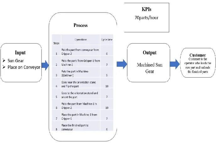
4.4.2. SUN GEAR MECHANISM ... 36
4.5. FUTURE STATE OF RING GEAR MECHANISM. ... 39
4.5.1. RING GEAR MECHANISM (IMPROVEMENT) ... 39
4.6. SIMULATION OF ROBOT CELL ... 43
4.7. SIMULATION ... 44
4.8. CHALLENGES FACED WHILE SIMULATING THE ROBOT CELL ... 47
5. ANALYSIS ... 48
5.1. OPTIMIZATION OF THE RING GEAR ... 48
5.2. SIMULATION INTEGRATION ... 51
5.2.1. CURRENT VS FUTURE STATE PRODUCTION SYSTEM DEVELOPMENT PROCESS AT LEAX. ... 52
5.2.4. ONLINE VS OFFLINE PROGRAMMING ... 54
6. CONCLUSION ANS RECOMENDATION ... 55
7. REFERENCE ... 57
List of Figures
Figure 1: Research Process ... 12
Figure 2: Simulation Steps (Law, 2009) ... 15
Figure 3: The nine pillars of Industry 4.0 (Rubmann, et al., 2015) ... Error! Bookmark not defined. Figure 4: Production System Development (Bruch & Bellgran, 2013) ... 22
Figure 5: Industrial Robot (ABB, 2020) ... 22
Figure 6: IRB 6600-175/2.8 (ABB, 2020) ... 23
Figure 7: RobotStudio simulation window (ABB, 2020) ... 25
Figure 8: Summary of the map ... 34
Figure 9: Mapping of flow ... 35
Figure 10: Summary of the map ... 38
Figure 11: Summary of the map ... 41
Figure 12: Mapping of flow ... 42
Figure 13: Conceptual Model ... 43
Figure 14: Simulation of Existing robot cell... 44
Figure 15: Robot cell virtual environment ... 45
Figure 16: Station logic ... 46
Figure 17: Debugging of program ... 47
Figure 18: Utilization ... 49
Figure 19: KPIs ... 50
Figure 20: One cycle of the robot (before and after) ... 50
Figure 21: Utilization ... 51
Figure 21: Creating empty station in RobotStudio ... 63
Figure 22: Creating System from backup ... 64
Figure 23: Creating new virtual controller... 65
Figure 24: Adding existing virtual controller ... 66
Figure 25: Smart component ... 66
Figure 26: Graphical representation of the task ... 70
Figure 27: Graphical representation of utilization ... 71
Figure 28: Graphical representation of sun gear mechanism ... 72
Figure 29: Graphical representation of utilization ... 73
Figure 30: Graphical representation of ring gear mechanism ... 74
Figure 31: Graphical representation of utilization ... 75
List of Table
Table 1: Process of robot action in ring gear mechanism ... 32Table 2: Overview of signal flow for ring gear ... 33
Table 3: process of robot action in sun gear mechanism ... 36
Table 4: Overview of signal flow for sun gear ... 37
Table 5: Ring gear process ... 39
Table 6: overview of future state flow of information for ring gear ... 40
Table 7: Online vs offline programming ... 54
Table 8: Ring Gear Mechanism ... 68
Table 9: Operation time ... 69
Table 10: Total time and Working time ... 70
Table 12: Sun Gear Mechanism ... 71
Table 13: Operation Time ... 72
Table 14: Total Time and Working Time ... 72
Table 15: Utilization ... 72
Table 16: Ring Gear Mechanism ... 73
Table 17: Operation Time ... 74
Table 18: Total time and Working Time ... 74
ABBREVIATIONS
CAD Computer Aided Design IR Industrial Robot
I/O Input Output signal
IDT School of Innovation, Design and Engineering Mdh Mälardalens University
OLP Offline Programming
PSD Production System Development
RS RobotStudio
TCP Tool Center Point VSM Value Stream Mapping
1. INTRODUCTION
1.1. Background
The ever-changing dynamic manufacturing environment has caused disruptive changes in various manufacturing perspectives, such as operations, management, human resources, research and development, sustainability, technology, and digitization (Garcia, et al., 2018). These changes are caused due to constantly emerging customer demands, varying market opportunities, technological advancements, and the need for customer-specific customization (Bruch & Rosio, 2015), creating a sense of competition among the industries which are under severe pressure to increase their competitiveness (Andersson & Bellgran, 2015). To sustain these disruptive changes and maintain competitiveness in the global market, companies need to continually work towards improving their production performance, successfully developing and implementing innovative production practices, and producing high-quality products in shorter lead times at optimum costs (Bellgran & Safsten, 2009). For instance, manufacturing companies failing to change and improve themselves can result in an increasing gap between market requirements and production performance, leading to lost competitiveness, ultimately losing market share and profitability (Andersson & Bellgran, 2015). The variations and fluctuations in customer demands can be satisfied by introducing new technologies into manufacturing systems, which brings in varying flexibility and agility character into production (Kivikunnas, et al., 2010). The introduction of robotization into manufacturing systems has fully automated the manual, repetitive, strenuous, and hazardous tasks and has performed at high efficiency and safety. Literature shows that using robots in production lines has relatively decreased 50% of production cost, productivity increase by 30%, and 85% utilization rate in few manufacturing sectors (Golda, et al., 2018). Industry 4.0 concept also helps in increases efficiency through digitalization (Stancioiu, 2017).
Industrial robots in manufacturing systems increase the productivity and quality of the process. Robots replace humans in performing a wide range of repetitive tasks, which would otherwise be hazardous, tedious, and time-consuming (Li & Zhang, 2011). A robot can perform a variant process, which supports the flexibility of the cell's alternative configuration. The robot can efficiently carry out various operations in an organized sequence, such as transportation, material handling, and machining (Papakostas, et al., 2011). The robot's effective and efficient programming helps achieve flexibility in the production process because the robot's programming aids the robot to perform various tasks and motions. The robot's programming has two approaches, which are classified as online and offline programming. Usually, the programming of robot tasks is performed by teaching each position to the robot in the real work cell, known as online programming (Li & Zhang, 2011)The involvement of real robots is not necessary for an offline programming method. This approach benefits in reducing the robot downtime, and the production line will not be affected (Jen Yap, et al., 2014).
The offline programming is a simulation software that helps in simulating the robot using a Virtual Robot controller. The simulation tool lets users recreate the production environment and program a robot and calculate the cycle time without a real robot. Accurate representation of the real world is essential because most of the offline programming information sent to the virtual robot is positional. Offline Programming is a software component that offers an
application-specific tool that helps generate a robot program. The user can load their CAD drawing into a simulation tool with the help of a software component that can generate a robot path by joining points in a 3D space or selecting the whole space and letting the simulation software generate a path. The generated path inside the CAD-based programming is usually customized to a specific application such as paint, weld, pick and place, etc. The robot simulation is user-friendly, wherein a user can generate a robot path for a particular process with minimum robot knowledge (Rossano, et al., 2013).
1.2. Problem formulation
As a result of rapid technology development around the world, automation of industries has become prominent. Industry 4.0 provides tools essential for production efficiencies, changing manufacturing relationships traditionally to achieve the global market requirement. Robot-based production systems have been a vital part of industrial manufacturing strategy. However, the increasing complexity of integration, demand fluctuations, and planning has created a need for the manufacturing industry to be more flexible and agile. On the contrary, robots are meant to perform standard repetitive works, making it difficult for the robotised production lines to adjust to variations. The integration of simulation aims to increase efficiency, ramp-up time, and optimize design, which could also be achieved by estimating an automated system's critical characteristics before its physical existence (Laemmle & Gust, 2019). To simulate the robot system, one can visualize the robot system in a realistic way, where the different scenarios can be tested to optimize the work cell and increase productivity(Kumar & Phrommathed, 2006) in their research shows that data analysis, process mapping, and computer simulation can be beneficial because a change in the information flow, system, procedure, etc., can be analyzed without disturbing the entire system (Zlajpah, 2008). Therefore the thesis focus on integrating simulation tool into the company production cell and display the use of simulation when optimizing the robot cell. Two research questions have been framed and listed below to fulfill the purpose of the thesis.
1.3. Aim and Research questions
The aim of the project is to investigate simulation as a tool to optimize a robot cell and to incorporate simulation as part of production system development in a manufacturing company. Thus, two research questions have been formulated to achieve the aim of the thesis.
RQ 1: How can simulation be used when optimizing the work of a robot in a workstation?
RQ 2: How can simulation be integrated in a company’s production development process?
1.4. Limitations
The thesis research area was to optimize the robot and integrate the simulation into company’s production development process. The case study will only focus on a specific cell, where ring gear and sun gear are machined individually. Further, only the ring gear mechanism is taken
into consideration for future studies. The simulation tool used in this case study is ABB RobotStudio. The company uses ABB Robots in the cell for production. Hence, ABB RobotStudio was selected to simulate the robot cell. The data collected for building the simulation is through observation, interview, and documentation. All the collected data is provided by LEAX GROUP.
2. RESEARCH METHOD
This part of the thesis represents the research methodology where the research process, the method used to collect data is discussed. Further the process of data collection, case study, simulation study, data analysis and quality of the data is presented.
2.1. Research Process
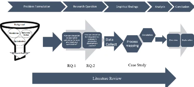
The research process for this thesis is started by formulating the problems by identifying the broader field of the particular area for investigation and then the broader area has been divided to understand the relationship between the sub-areas, followed by formulating two research questions which help in achieving the aim of the research. Further, the required data is collected through semi-structured interview with company personnel, observations, and company’s data logs. Simultaneously, a literature for the relevant topic was reviewed by focusing on an area of optimization of a robot using simulation as a tool and integration of the simulation for production development. Later, the process mapping and simulation model concept was developed using the data collected, and then the verification and validation of the simulation model were conducted. Further, the empirical findings' result was analysed with the collected research literature to achieve the research objective. The overview of the research process highlighted in Figure 1.
Figure 1: Research Process
2.2. Data Collection
Data collection helps in drawing inferences and conclusion for the research study. The data collection method is divided into two categories such as primary and secondary data (Kothari, 2004).
2.2.1. Primary Data
Data gathering by direct means or in-person by interview or observation is referred to as primary data. The data acquired from prior work such as journal, thesis report etc. are referred to as secondary data (Kothari, 2004). Due to improved technology, the availability of secondary data has been more accessible, and the easy accessibility of the research publication database helped the researcher attain secondary data. There are different source and technic used to collect the required data for the case study (Bell, 2014). The type of technique used in this thesis to collect data is through observation, documentation, and interview.
2.2.1.1. Observation method (Primary data)
Observation method is one of the most used method for data collection. Observation acts as a scientific tool and a data collection method when performing a formulate research objective, which is recorded and planned systematically. The observation was conducted to test and manage validity and reliability (Kothari, 2004). A visit to the LEAX group in Rezekne aims for data collection. A small plant tour and company presentation were given to the researcher and allowed to examine and observe the process of Robot cell three during the first day of the study visit. The study aims in understand the robot process flow from picking up raw material until placing the finished part on to the conveyor.
2.2.1.2. Documentation (Primary data)
The collected data regarding documentation includes the CAD model of the robot cell, and the data collected from an observation is also documented for further use. The collected CAD model helped in building the virtual environment in the simulation software.
2.2.1.3. Interviews method (Primary data)
The data collection for the interview method involves the presentation of oral-verbal questioning and response (Kothari, 2004). Personal interviews and telephonic interviews are used to collect the required data in this case study and is explained below.
2.2.1.3.1. Personal interview (Primary data)
A personal interview is one such interview methods where the person must ask questions to the other person in a face-to-face contact (Kothari, 2004). The interviews were conducted with the Automation engineer in LEAX Rezekne during the study visit. On the second day of the study visit, an interview was conducted to understand the robot cell's process. The questions answer in the interview were written on a sheet of paper and then transferred into an excel sheet. The data collected from the interview helped in building a robot process map. During the interview, the Robot cell backup folder from the flex pendant was requested and collected.
2.2.1.3.2. Telephonic interview
A telephonic interview is a method of collecting information or data through the telephone. This method is not widely used but plays a vital role in the industry, specifically in development
areas. This method benefits in flexibility, quick response, cheaper, etc (Kothari, 2004). During the thesis work, many questions were raised, and the raised question was cleared by conducting several skype call meetings. Most of the information regarding sensors were collected through a skype call and documented to continue with the simulation model. Even the progress of the project was also displayed through skype meetings.
2.2.2. Secondary Data
Even though the research is dependent on the primary data, it is essential to study secondary data to understand the theory behind the research topic. The secondary data can be used to analyse the obtained research work, which is collected from primary data. The researcher in the research work uses both primary and secondary data. The secondary data is collected by accessing the database through Mälardalens University (MDH) website.
2.2.2.1. Literature review (Secondary data)
The literature review deals with the three main topics: industrial robot, simulation, and optimization in the manufacturing industry. The three main topics in the literature review aim to determining the relationship between the research problem and the body of knowledge in the specific field to understand the researcher's knowledge broadly, improve research methodology, and clarify the research problem. The literature review explains the nine pillars of industry 4.0 and then narrowed down to industrial robot, simulation, and offline programming.
The extraction of scientific papers and the books used in a literature study was collected from a database such as Scopus, Emerald Insight, IEEE explorer, DiVA Research Gate, and Google Scholar. The keyword used to search the specific area of research are “Industry 4.0”, “simulation,” “offline programming,” “Industrial robot,” “process mapping”, and “robot studio.” Based on the keyword the paper was selected, further numerous filers were used to collect the relevant papers. The literature search was limited to the past 30 years. First, the abstract was thoroughly examined to know the paper outline and then a relevant article was selected for the study. Further, the snowball technique was followed to collect more topic-related articles. Finally, the scientific articles and the books on the relevant topic was collected.
2.3. Case Study
The case study is performed to understand the complexity of the situation in a better way. The researcher can also maintain the holistic and significant properties of real-life events by conducting case studies (Yin, 2013). A case study can be defined as a detailed, multifaceted examination with a qualitative research method. The study can be conducted in detail and can be trusted on a certain data source (Orum, et al., 1991). The case study approach implemented for this thesis comprises of acquisition of data for simulating the robot cell, analysing the simulation study, and drawing conclusion. This thesis employs a single case study, which benefits in more profound observation of the study. The case study research includes multiple data collection methods such as observation, interviews, questionnaires, and relevant documents from multiple sources. The implementation of multiple data collection techniques
and sources manipulate the outcome of credibility and give different clarification (Graeme & Nargiza, 2018). The required data for this thesis was collected by conducting interviews with concerned company employees, documentation and by observation.
There are two main focal research methodologies in academic which includes qualitative, and quantitative research methods. Qualitative research is a scientific method of observation to collect a non-numerical data, whereas quantitative research is the observation of empirical investigation through mathematical, statistical, and computational techniques (Giver, 2008) (Seale, 2004). This research is a qualitative study because the process includes the procedure and the emerging questions with data collection and analysing the data to present clarification for the data (Creswell, 2013).
2.4. Simulation Study
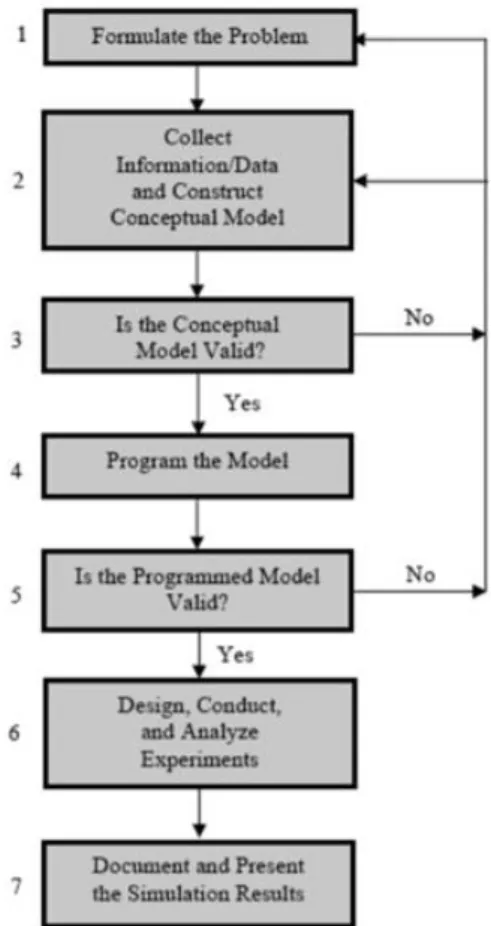
The simulation was built based on the data collected through observation, interviews, and documentation. The outcome of the process mapping discussed in section4 also supported in building the simulation model. The process of simulation on this case study if followed by several steps, which are listed in Figure 2.
Figure 2: Simulation Steps (Law, 2009)
Step-1: Formulating the problem.
The first and the most important stage of the simulation journey is problem formulation. The team must state the problem and the problem formulated must be shared with the people who is involved in the study (Law, 2009). The problem formulation has begun through meeting with concerned manager at LEAX. In the meeting, the problem was explained, understood, and
discussed to lay foundation for scope, boundary conditions, expected goal, limitations of the problem and outcomes from the research. After a meeting, a decision has been made for visiting production facility of LEAX in Latvia for physical visualization and comparison from theory to practicality for checking discrepancies in formulated problem.
Step-2: Collect information/ data and construct conceptual model
The building of the conceptual model and data collection are the two steps followed in this process. Inputs are the factors used for building the model, and the output is the company's required goal. Hence, the better way is to start the model in a simple way and through the process of data collection complexity of the model increases gradually. (Banks, et al., 2010). The conceptual model was built to visualize and understand the input and output steps while building the model. The conceptual model was built after the first meeting in the company. The data collection process and techniques for simulation model was described in section 2.2 and the conceptual model for the conducted simulation is shown in Figure 13
Step-3: Is the conceptual model valid?
In the simulation Journey this step is considered as a gate of checkpoint before moving to next step. The purpose of this step is to validate the result from the previous step for ensuring no errors by discussing with concerned people (Law, 2009). To ensure the good result of the simulation model the researcher need to go back to the previous step, clear the errors and then move forward to the next phase. Several meeting with the company employees was conducted through skype call for the collection of required data.
Step-4: Program the model.
If both the formulated problem and the conceptual model is validated based on the data collected. The next step is to model a cell using one of the simulation tools (Law, 2009). In this thesis, ABB Robot Studio is used as a simulation tool to build the model.
Step-5: Is the program model Valid?
This process is considered as one of the checkpoints in the flow. After the completion of the program, the next step is to check the program. The checking of the program is known as verification. Validation is also taken place parallelly. Validation is the comparison of the simulation program with the real word system (Shannon , 1998). The verification of the simulation model was conducted by running the model for multiple times. This process is conducted to know the robot performance and to verify the proper running of smart component and sensor used. Later the model was validated by comparing the outcome of simulation model with a video of robot test run.
Step-6: Design, Conduct and analyse Experiments.
When the above process is completed without any errors, the next step is to try the model with the possible scenarios and comparing the result (Law, 2009). Further scenarios were not simulated because any more optimization efforts would overburden the robot by pushing its
utilization to 100% making it redundant to changes and even the two machines in the robot cell are running with least possible cycle time.
Step-7: Documentation and presenting the simulation result.
This is the last step in the simulation process where the result is documented and presented to stakeholders. Animation, tables, chart, and pictures are different ways of presentation (Law, 2009). The documentation for simulation tool used in this case study is by taking a backup folder form the simulation software, which is explained in appendices and the presentation of the simulation result is done by taking a screen recording of the running simulation model.
2.5. Data Analysis
The data analysis comprises of data collection and their method in this case study. The collection of data through observation, documentation and interviews for empirical findings and the data collected for building the theoretical findings are analysed thoroughly and categorised to answer the research question. The process of data analysis follows the steps of data reduction, data display and verification/conclusion drawings which is suggested by (Miles & Huberman, 1994).
2.5.1. Data Reduction
The process of simplifying, focusing, selecting, abstracting, and transforming the data is referred to as data reduction. When the researcher decides the case, research question and the data collection approach, the data reduction comes into picture (Miles & Huberman, 1994). In this thesis the data collected from observation, documentation, and interview were used to serve the research questions and to know the answer for the framed questions.
2.5.2. Data Display
Data display is the second most process of data analysis activities. Basically, display is an organized, compressed information that end up in drawing conclusion and action. Displaying of data helps researcher in understanding the scenario and even helps in proposing an improved scenario (Miles & Huberman, 1994). In this case study the data of the process mapping was displayed through Excel sheet and the simulation model result was displayed through screen recording. The process mapping helped in understanding the process and suggesting the future improved scenario and the simulation model helps in visualization of the process and testing the different scenarios without disturbing the real production cell. The data displayed in the empirical findings is compared with theoretical framework to drawing the conclusion.
2.5.3. Conclusion drawing and verification.
The third step of data analysis is conclusion drawing and verification. Conclusion drawing is the process of considering the data collected and to review their suggestion for the questions framed. Whereas, verification is reviewing the data for many times to cross verify their conclusion (Miles & Huberman, 1994). Using the result of the collected data the research question was answered and the conclusion was drawn. The simulation model was reverified
for several time to know whether the model is imitating the real world. The outcome of simulation model and the process mapping of the robot cell was compared with the recorded video of the robot cell production line.
2.6. Quality of Research
Based on validity and reliability, the quality of the research can be measured. The right performance can be measured using the right tool for the right task, which becomes a vital factor for validity. The similar result obtained by the repetitive test experiment is estimated in reliability. Hence, validity and reliability play a crucial role in evaluating the quality of the research (Yin, 2009). The research quality of the case study lies in earning credibility, where the method can be useful to another robot cell in the manufacturing industry. In general, there are four criteria to address the quality of the research, namely: constructed validity, external validity, internal validity, and reliability.
One way of testing the validity is through constructed validity. It is used to ensure that the actual tool is used for the proposed research, which can be reached by triangulation (Yin, 2009). The thesis essential tool for collecting data is through observation, documentation, and interview, which is explained in section 2.2. To improve the quality of the gathered data, regular supervision was done by the MDH supervisor and several meetings was conducted for the employee of the company. Triangulation is a method used in this thesis to compare and verify the various collected data used in this research with reviewed literature.
External validity is used to compare the empirical findings with the existing research method or case study in a similar body of knowledge (Yin, 2009). The thesis's external validity is conducted by performing the empirical research and comparing it with the findings of the literature review. The opportunity for a more detailed analysis of the data is possible because the research study is based on one single case study.
Internal validity helps perform and build a relationship of an optimal triangulation pattern between the collected data and aim to clarify and explain how to connect the data with each other (Yves-Chantal, 2010). The interview conducted with the case company’s employee highlights the collected data for process mapping and simulation of the robot cell. The collected data was further strengthened by the researcher's onsite observation and examining the recorded video of the robot cell process.
The explanation of every part of the research with transparency to fully understand the executed study is known as reliability (Yin, 2009). The data collected in this thesis was transferred to an excel spread sheet and was further used to build the simulation model. The developed process mapping and the robot cell simulation is described in the chapter4. The verification and validation of the model are tested by running the model for several times, and the outcome of the model is compared with the real world. This helps in achieving the reliability of the model. The model can even be used for testing the different scenarios in the robot cell.
3. THEORETIC FRAMEWORK
Here the theoretical knowledge is built based on the scientific article, books, and conference paper. This section highlights Industry 4.0, the manufacturing industry, and its production system development. The section highlights the introduction of the robot and ways of programming the robot and concludes by explaining the process of mapping.
3.1. Industry 4.0
Due to the increase in competition between many manufacturing companies, it is necessary to improve their production system's efficiency and effectiveness (Jayachitra & Prasad, 2010). A company must change rapidly in digital technology since it is one of the crucial factors in developing its production system (Roll, et al., 2019). The fourth industrial revolution helps achieve digitalization in many manufacturing industrial areas such as production, planning, and logistic. The concept of industry 4.0 aims in fulfilling the needs for a more flexible, reliable, and efficient process of the industry using digital technology (Damiani et al., 2018). The industrial revolution started with the mechanisation of the steam power and cotton gin, which played an essential role during the first industrial revolution in the 1700s. During the second industrial revolution, steel production, electricity, and petroleum bought many changes to society. Electronics, telecommunications, and computers, the third Industrial revolution (Chitiba, 2018). The concept of industry 4.0 or the fourth industrial revolution helps increase the resource's efficiency through digitalization. Industry 4.0 is one of many industries' steps to be more competitive and improve their efficiency (Stancioiu, 2017).
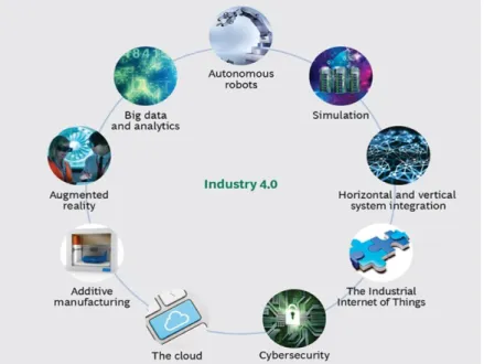
Nine Pillars of Industry 4.0
The nine pillars of Industry 4.0 is shown in Error! Reference source not found. and a short explanation is given below. These 9 pillars of Industry 4.0 helps in optimizing, automating, and integrating the flow of production cell, which enhances in increasing the efficiency of the company (Vaidya, et al., 2018).
3.1.1. Big Data and Analysis
The collection and evaluation of various data from a different source which are stored in different structure to gain value and even supports real-time decision making (Gerbert, et al., 2015).
3.1.2. Autonomous Robot
Nowadays, tackling complex tasks has become more accessible by using robots in manufacturing industries. Robots have become more flexible, cooperative, and autonomous. They even create a safe environment and work with humans parallelly (Gerbert, et al., 2015).
3.1.3. Simulation
Simulation is one of the tool established to evaluate and predict the complex and sophisticated performance of the system (Xu, et al., 2016). Simulation in production process not only reduce the down time but also helps in optimizing the process in production system (Simons, et al., 2017).
3.1.4. Horizontal and vertical integration
The two crucial mechanisms used in the industrial organization are self-optimization and integration. The industry used horizontal and vertical integration as one of the strategies in their business. The acquiring of the company from other companies with the same business is referred to as horizontal integration. Whereas in vertical integration, the company take control of production stages or product distribution (Magidel, et al., 2018).
3.1.5. The Industrial Internet of Things
In modern wireless technology, the Internet of Things (IoT) gains a broader interest. Things such as sensors, actuators, radio frequency identification, mobile phone, etc. are capable of interacting with each other and unite their fellow mates to achieve their common goal (Hozdić, 2015).
3.1.6. Cyber Physical system
Cyber means communication, computation, and control that are switched, discrete, and logical. Whereas the physical refers to human-made and natural system that is controlled by a law of physics and continuously operated. The management of an interconnected system between computational ability and physical skills of transformative technology is known as a cyber-physical system (Wang & Wang, 2016).
3.1.7. Additive Manufacturing
The technology of building the 3D object by adding layer by layer material is known as additive manufacturing. Additive manufacturing is a method which is commonly used for producing a small quantity of product which is complex and light weight in design. The transportation
distance and stock on hand can be reduced by a high-performance and reorganized additive manufacturing system (Gerbert, et al., 2015).
3.1.8. Augmented Reality
A technology that connects reality with the virtual environment is known as augmented reality. There are various services supported by augmented reality, such as providing repair instruction through mobile devices and picking material in a warehouse. The decision making and work procedure can be improved through augmented reality by providing real-time information for workers (Gerbert, et al., 2015).
3.2. Manufacturing industry
The transformation of material and information into goods for the fulfilment of customer need is known as manufacturing. Manufacturing industries are more focussed on transforming their production process towards flexibility (Dimitris, et al., 2014). Environmental change and customer demand have led the company to revise its production strategy. The variations and fluctuations in customer demands can be met by introducing new technologies into manufacturing systems (Kivikunnas, et al., 2010). The increase in the trend towards decentralization and globalization of the manufacturing system entails exchanging and collaboration of real-time information between the various production development nodes such as setup planning, designing, machining, assembly, production scheduling, etc. This collaboration can be achieved by employing industry 4.0 in the production system. Digital technology helps in fulfilling the needs for more reliable, flexible, and optimized industrial processes. Employing Industry 4.0 and implementing digital tools such as 3D modelling, virtual reality, and simulation in the manufacturing companies can pave the way for developing the production system and making different optimal decisions (Monostori, et al., 2016). These digital tools play a vital role in improving the production processes in manufacturing companies, which leads to achieve flexibility in the production process and reach the customer demand (Monostori, et al., 2016).
3.3. Production System Development
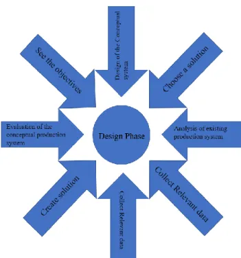
The companies now a day’s urge to develop their production system. (Bellgran & Safsten, n.d.)mentioned that the need for an increase in capacity, introduction of the new product or change in a product, improving the work environment, etc. are some of the reasons for production system development. The development of the production system process has been divided into three steps: design, building, and evaluation. In the design phase, the relevant data and information are collected and then the production's conceptual model is made and evaluated. The design phase even identifies the process of improving the current state and identifying the appropriate solution. Figure 4 indicates the different steps of the design phase. After the design phase, the building of the production system and then followed by evaluation of the implemented solution in the production system arise (Bruch & Bellgran, 2013).
Figure 4: Production System Development (Bruch & Bellgran, 2013)
3.4. Industrial Robot
The International Organization for Standardization defines industrial robot as “automatically controlled, reprogrammable, multipurpose manipulator programmable in three or more axes” (Manipulating Industrial Robots, n.d.). An industrial robot is a programmable robot which is typically used in industrial application. Based on the application and the workspace the configuration of the robot is differed. The customer requirement decides the design process of the robot. The requirement includes workspace, application of the robot, reach, accuracy, repeatability, payload, resolution, and degree of freedom. The robot can be equipped to perform various applications such as material handling, assembly, welding, gluing, and painting (Reddy & Brioso, 2011). The robot cell is equipped with a controller and flex pendant, where the controlling decision and logic are made in the controller, and flex pendant is used to load and operate the program. The industrial robot's physical construction includes several jointed links with an electric motor used to activate the link. The basic joint is either a revolute or prismatic joint. A revolute joint is typically a servo, whereas a prismatic joint is usually a pneumatic or hydraulic system (Morten, et al., 2015) (Johan, 2007). Figure 5 indicates the six-axis industrial robot.
An industrial robot can be used to increase the productivity and quality of the production process. The wide range of repetitive tasks, which is tedious, time-consuming, and dangerous by humans, has been replaced by robots. Hence industrial robot is beneficial in achieving flexibility and quality in the production system. However, the system's flexibility can only be achieved through effective and efficient programming of the industrial robot. Online programming is the traditional way of programming the robot, which is tedious and time consumption (Li & Zhang, 2011). The other way of programming is through offline programming, where a real robot's involvement is not necessary. This programming benefits in risk reduction, increase productivity, and reduces robot downtime (Fang, et al., 2018).
3.4.1. IRB 6600
The robot used in this thesis is IRB 6600, which is a model in ABB’s robot family. The robot comes in several versions, with different arm length and machining handling capacity. As the robot can bend fully backward, the range of working is extended greatly, and the robot can be well fitted into the dense production line. The typical application area of the robot is material handling, machine tending, and spot welding. The motion and load of the machine can be monitored using the built-in service information system. The robot's active safety features protect the workers in the unlikely event of an accident and the robot itself. Collision detection reduces the collision force significantly, especially when managing a high payload. The active brake system controls the breaking while ensuring the robot maintains its path but allows rapid recovery. The version, arm length, and machining handling capacity of the robot used in this thesis are IRB 6600-175/2.8. Where IRB 6600 is a robot type, 175 is a handling capacity in kilograms, and 2.8 is a reach of the robot in the meter. The other way of programming is offline programming, where a real robot's involvement is not necessary. This programming benefits in risk reduction, increase productivity and reduces robot downtime (ABB, 2020). Figure 6
shows the ABB Robot which is used in this thesis work.
3.4.2. Online Programming
The guiding of the robot through the desired path using a teach pendant with the help of a skilled operator is known as online programming. The online programming includes jogging the robot, recording a specific point in the robot controller, and creating the movement command by utilizing the recorded point. Programming the robot requires an operator responsible for guiding the robot, orienting the robot in six-degree-of-freedom, and maintaining the desired position. Despite using online programming is simple and widely used, it has several drawbacks. The robot which is jogged using a teach pendant is not intuitive as the robot system is usually defined by many coordinate systems. Jogging the robot accurately through the desired position without any collision is very difficult and time-consuming, especially when there is a complect workpiece geometry or in a complicated process. Besides, many drawbacks testing for the generated program must be done for reachability and safety reasons before the program is convincing. The robot program that is generated using the lead-through method is not much flexible and reusable. The slight change in the process will demand repetition of the process, which is tedious and time consumption. The quality of the created robot motion will depend on the operator skill level (Pan, et al., 2012).
3.5. Robot simulation
Simulation is one of the nine pillars of Industry 4.0, which drives innovation and helps visualize and forecast for producing flawless products, assembly lines, and real-world design systems, which minimizes cost and maximizes output. (Banks, 1998) defines Simulation as the imitation of the operation of a real-world process or system over time. A simulation is a powerful tool that supports planning, design, analysis, and decision-making in different production development areas. Simulation is widely used in all fields, especially in the manufacturing field. Simulation, which is recognized as an essential tool in robotics, contributes to designing new products, investigating the performance, and designing the process. The structural, characteristics, and functional study of the robot system can be allowed in Simulation. The role of the Simulation becomes more critical as the complexity of the system increases. Therefore, the simulation tool can surely improve the system's design, development, and operation (Zlajpah, 2008). This can be viewed through animation and graphical means in a real fashion on the computer. Hence, an operation's manufacturing outcome can easily be observed without utilizing any actual equipment, which results in cost-efficient and minimizing risk. Simulation has various commercial software to provide solutions for facility layout planning involving robot work cells. Specifically, for industrial robot simulation and visualization, various commercial software has been developed. The simulation software helps check reachability, safety issues, workspace, and other industrial robot aspects (Fauadi & Jumali, 2008). There are many simulation concepts available in today's environment, including discreet event simulation, continuous or geometric Simulation, etc.
The idea of discreet event simulation is based on facility layout planning. The overall picture of simulating robot work cells can be achieved in discreet even Simulation, wherein the industrial robot is considered an event inside the robot cell. The detailed information such as path planning and robot programming is unavailable in this simulation type since the robot's command cannot be automatically generated from this simulation result. Besides, the unique
constraints and ergonomic issues are not considered in this simulation environment (Jahangirian, et al., 2010). Whereas in geometric or continuous Simulation, graphical representation within the constant time interval is available. During the manufacturing process, geometric Simulation is more appropriate for 3D visualization, collision detection, and offline programming. However, robot manufacturers developed various simulation software (Yap, et al., 2014). One such simulation software developed from the robot manufacturers in the ABB RobotStudio, which is used as a simulation tool in this thesis work.
Figure 7: RobotStudio simulation window (ABB, 2020)
ABB RobotStudio is a commercial software application for simulating and offline programming using the ABB robot and its application. This application consists of a virtual robot model that with basic functionality. The application comes with virtual control for a robot that resembles the robot’s real controller. Offline Programming (OLP) is a method where the flexible robot program can be generated for complex robot paths. Offline Programming and robot simulation are powerful tools used to save money and time for end-users when designing the work cell. OLP method can be used to analyse and test various improvements planned to increase the robotised production system's efficiency without hindering the operations. OLP shifts the robot’s burden of programming in the workshop to a computer model environment, where the robot can be jogged to its desired position using a simulated robot (Pan, et al.,2012).
Figure 7 indicates the robot's offline programming in a manufacturing cell, including the simulation window, rapid language test programming window (a high-level programming language used for controlling ABB industrial robot), signal control panel, and command ribbon. The automatic path generation of the robot is possible using the 3D CAD model. The virtual teach pendant can even be used to jog and record some robot's configuration and position (Cristoiu & Nicolescu, 2017). By using graphical programming, the movement of the robot can be created, editing, and debugging. This tool is widely used in many automation
industries by robot programmers and mechanical designers. It is even used in troubleshooting and remote maintenance by taking a virtual copy of the live system and then moving it offline to know the situation and study the system in depth. RobotStudio can verify the accessibility, reach, and collision between each path can be examined (Connolly, 2009).
Creating a workstation in a virtual environment will help in following: • Perceive conceptual design as a complex workplace.
• Possibility of interactive correction of the position of the workstations.
• Integration of CAD model into Robot Studio environment and recognition of edges and points which define the exact target of the robot,
• If the simulation is based on the use of the virtual controller, the kinematic motion of the robot can be visualized, which is equivalent to the real controller.
• Simulation of the material flow in the workplace.
• The whole simulation of the workplace can reduce the total cost of investment, as long as it is possible to determine the optimal solution in terms of material flow and the overall layout of particular workplaces (Holubek, et at.,2014).
3.5.1.1. Key Steps of offline programming and simulation
• 3D CAD model generation
The indispensable design phase for a production system is Computer-Aided Design (CAD). Offline programming starts from creating a 3D CAD model of a workstation and workpiece (Pan, et al., 2012). The subsequent integration of the various CAD data into the simulation environment often creates different 3D rendering and compatibility issues. Hence, it is essential to use various CAD converters where different CAD formats can be obtained, which allows integration of CAD model into the simulation environment. The 3D CAD model, used in the simulation environment, helps in testing reachability and visualization of the virtual robot cell environment (Holubek1, et al., 2014).
• Trajectory planning
The robot configuration needs to be selected by considering issues such as reachability, collision avoidance, minimising configuration transition, etc because the inverse kinematics of industrial robots usually have multiple solutions in cartesian space. By utilizing the CAD model, the path can be automatically generated in the RobotStudio. The cycle time can even be reduced in RobotStudio by optimizing acceleration, speed, etc. OLP can even deal with the issue such as reachability, transition, collision avoidance, etc (Marcos, et al., 2013).
• I/O signals
The process includes the necessary I/O (input and output) control signals adding to the work cell's equipment. This process is used to achieve the interaction between the robot and the external equipment. The animation effect in RobotStudio can be achieved through an effective tool known as a smart component. I/O boards provide a common signal such as digital input, analog input, digital output, analog output, and conveyor chain tracking. I/O board is a device
located in the field bus, used to connect the I/O signal of the smart component with the I/O signal of the robot, where the input signal of the robot end in the output signal of the smart component, and the output signal of the robot end is the input signal of the smart component (Li & Liu, 2019).
• Synchronization
After generating a path and connecting every signal to the robot, synchronization of the network of signals is necessary. The simulation and modelling part and the RAPID programming and controller parts are the two separate parts in RobotStudio. In the simulation and modelling part, the work object, target, path, signals, and the virtual environment are created. After modelling the simulation, the created target, path, and signals are generated to represent close to the actual system. The results are a generation on RAPID programming, where the code can be used to run both the virtual and real robot (Persson & Norrman, 2018). • Calibration
(Hayani, 2014) in his study, says that the offline program can be downloaded after satisfaction from the robot's result and performance. The program can then be run using the real robot. Before running the program, it is necessary to calibrate the program. The synchronization of TCP and workpiece position can be seen in this procedure. He even mentioned that the robot's TCP should be defined in the real robot and then brought back to the simulation environment to modify the actual definition. This process helps in programming the robot in a perfect position, and then the target and path using the CAD model can be generated in the virtual environment. The created target and path generated in the virtual environment are brought back into the real world and modified (Hayani, 2014).
3.5.2. Advantages and disadvantages of Offline Programming (OLP).
There are many advantages to the offline programming method.
• In offline programming, one does not require a real robot for the process. The downtime of the robot can be reduced using OLP. The development of the robot's program can be carried on in OLP rather than programming it on the production site. It is more flexible for generating programs offline rather than using the jog-and-teach method.
• The program's integration is quicker by picking the required part of the program, and the routine developed earlier can also be included easily in the new program.
• OLP method can be incorporated into the simulation, which results in the pre-checking of the program. Thereby the movement of the robot can be confirmed. This even improves the minimization of the errors and hence increases safety and productivity.
• It is even possible to optimize the workspace layout, and the robot task can also be planned.
Disadvantages of OLP:
• As the OLP package is quite expensive, it is difficult to perform OLP in a small product volume because it is difficult to justify economically.
• The associated errors when calibrating robot requires expensive software, measurement hardware, and technical knowledge.
• When the robot is programmed offline, the next step is to test the program with the real robot to verify the correctness of the work. Due to calibration error, it may lead to a crash of a robot.
• Accurate modeling of the robot cell is required in the OLP method (Neto & Mendes, 2013).
3.6. Process Mapping
Process mapping is one of the tools which efficiently helps in modelling simulation. The sequence of activities that are represented in a diagrammatic manner is referred to as a process map. The map helps in visualizing all the processes in a sequence using graphical design (Heher & Chen, 2017). Process mapping is a pair of analytical tools and process intervention, where in-process intervention, the errors are reduced to improve the performance. Whereas in the analytical tool, the task's analysis is done by a graphical diagram, which includes the performance and activities of work. Process mapping helps in analysing and improving the cycle time, workflow, cost, and job satisfaction (Kalman, 2002).
3.6.1. Process mapping Techniques
There are various techniques used for process mapping. The views and perspectives are different in each process mapping. The techniques used for process mapping are listed below: 1. A Block diagram is one of the techniques which provides a quick summary of process
flow.
2. Decision American National Standard Institute (ANSI) flow chart, which alternates the process steps and identifies the decision steps.
3. Functional flow, which demonstrates the relationship between the process among departments.
4. The flowcharts show the physical flow of the activities called a String diagram or geographical flowchart.
5. Quality Process Language Diagram, which shows the interaction of information with a process.
6. Operational charts, where the value-added and non-value-added steps in the process are shown (Kalman, 2002).
3.6.2. Value Stream Mapping
Value Stream Mapping (VSM) is one of the tools used in mapping the process. An enterprise improvement tool that helps visualize the entire process flow, including information and material flow, is called VSM. VSM can be defined as collecting all value and non-value-added activities, which include the flow of material from raw material to end-users using the same resources. VSM is conducted in three steps, starting with constructing the current state of the process map and then followed by constructing the future state VSM and developing the action plan (Singh, et al.,2011). VSM management involves measuring, understanding, and improving the material and information flow and the collaboration of all tasks. This helps improve the companies' cost, quality, and service of the product where the company can stay competitive. It is one of the valuable tools that help understand the current state of the process and improve the process (Dal Forn, et al.,2014). There are many advantages of VSM, such as
displaying the product and information flow, information related inventory level, etc. Unfortunately, many disadvantages can also occur when using VSM because it is a Paper and pencil base technique and hence will be a limit in accuracy level. If the production system is complex, then there will be a failure in the mapping of flow (Braglia, et al.,2006).
4. EMPIRICAL FINDINGS
4.1. Company Background
The case company for this thesis work is LEAX Group AB, a manufacturing company. Lennart Berggren and Axel Seger founded LEAX Group in the year 1982. LEAX Group is one of the fastest-growing, privately-owned business groups with its origin in Köping, Sweden. From the beginning of the 1990s, the company has grown through acquisition and organic growth. There is a growth of 35% every year, and its turnover is more than SEK1,5 billion. About 1200 employees are working in the company. The case company's customers are mainly within the commercial vehicles, Mining and construction, Agriculture, General Industry, and Automotive Industry. Today the company has extended his territory holding five factories in Sweden, two in Latvia, one in Germany, one in Hungary, one in Brazil, and one in China. The company's vast territory enables them to meet their customer demand and needs of both closeness and low cost. The company's mission is to produce advanced components and subsystems for demanding customers. They provide flexible machining, assembly, and testing of subsystems and services in Management consultancy and measuring Technique. Its central vision is to become the world's most admired supplier of advanced machining and industrialization. LEAX Group uses automation with an industrial robot as a standard way of working to secure quality and production output. Automation also reduces ergonomy, workload and free up time for machine operators. The company used in this case study is located in Rezekne. In LEAX Rezekne, a new production area of 2000 meter square have been built during 2019 to support one Swedish automotive customer to produce gear components for a new electrical transmission. About 30 machines, together with automation equipment, are installed for this purpose. Three-part numbers are produced in the cell, and the yearly volume capacity is above 600,000 gears components.
4.2. Production Development Process
At the case company, a production development process starts by planning a development project. Then the right persons to perform the development process are roped in to form a cross-functional team.
The next step is defining operation performance and the machines involved in operating. Further, the team will go deeper into an investigation for calculating the cycle time for each part and then see if machines are available in the company. In parallel, the team looks for a suitable combination of the machines to perform tasks if the automation occurs. Then the team decides to use one robot for two or three machines in the cell. If there is a time for more automation, the company then goes with more machines as possible in the robot cell.
Then the team finalises the level of automation needed in the cell, the number of robots needed to perform the task, the machine required for operation, and the number of people required to operate the robot cell. The team then looks at the robot's suitable size to perform the task and then investigate whether the specified robot is available in the company. If not, the company invests the money in the specific robot to perform operations. The way of lift, reach of the robot, and handling the robot's weight are also considered while investing in the robot.
Depending on the cycle time and the machine's loading style, the team decides whether to use a single gripper or double gripper for the robot to perform the task. For example, the case study performed in the robot cell has Liebherr machine and Haas machine. In the Liebherr machine, there is a ring loader to load the part, whereas in the Haas machine, the parts in placed directly on the fixture, which requires more time and demand in the double gripper.
After finalizing the gripper and machines, designing the robot cell's layout in CAD software is conducted. The top view of the design highlights the reach of the robot. The detailed gripper is assigned, and the team waits until the gripper is ready. After the gripper is ready, the machine and the robot are placed in the real world's desired position.
The next step is programming the robot, where the team program the robot but not in a detailed manner. The movement of the robot is not programmed in the real world. The code for programming the robot is done RAPID using RobotStudio software by the company. After generating the program for the robot, it is tested on the real robot. The robot program and the communication between the robot and the machine are tested. Several weeks are required to see the proper working of the robot cell. After finalizing the proper working of the robot cell, the product development process is completed.
4.3. Current situation
One of the robot cells in Rezekne is handling two types of parts known as ring gear and sun gear, machined individually. The robot cell layout includes one ABB robot with a double gripper, two metalworking machines, one orientation stand, and one conveyor. The cycle time in the metalworking machine is short, and robot handling is the limitation for cell output. Capacity in the robot cell is one of the bottlenecks in the production line and must be utilized optimally. Production engineers at LEAX often focus on cycle time in metalworking machines. The robot's cycle time is often secondary due to a lack of experience, routines, and tools to optimize this.
Hence the purpose of this case study is to analyse a robot cell in the production line and use process mapping and simulation as a tool to optimize the existing robot cell. In this robot cell, two types of the part are known as the ring gear, and the sun gear produced individually. The process mapping for the robot cell was conducted, and the simulation of the robot cell was performed. The case study focuses on the integration of the simulation in the company’s production system development.
4.4. Current State analysis Process mapping:
For mapping the process, the primary input is to understand and collect relevant data of the process's actual steps. At LEAX, the robot cell's current process is understood through a semi-structured interview with the operator in charge of the robot cell. During the interview, the operator has explained step by step process. It is a cyclic process repeating throughout one type of part. The parts machined in this robot cell are ring gear and sun gear. Additional to the interview, the process has been recorded, and individual times for the steps have been clocked using a stopwatch for obtaining time data. The recorded videos were used to visualize the steps and compare the process map with the actual working process.
4.4.1. Ring Gear Mechanism
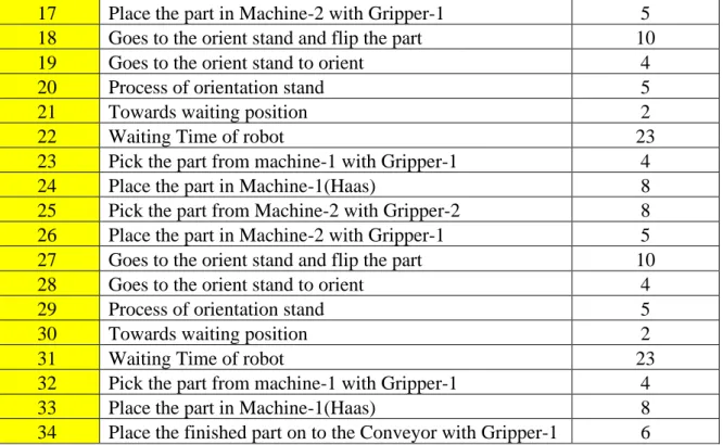
The ring gear machining involves several steps. These steps are divided into two parts. The first part consists of first initial steps which will be performed during the start of the new ring gear machining and involves setting up of the parts in the CNC machining. These steps are performed only at the start of ring gear machining batch and are not repeated. The latter steps are cyclic which are repeated all over the batch and listed in Table 1. Relevant times are noted through clocking time using stopwatch and compared with recorded videos.
The process for mapping the robot cell was conducted by following the below steps. • Identifying the customer.
Here in cell 3 the customer was an operator, who was loading the raw part to conveyor and unloading the finished part from the conveyor.
• Define valuable output.
The output from the cell 3 is the machined part which is kept on to the conveyor.
• Define input.
The input is the raw part which is needed to be machined in the cell. The input part on the conveyor in semi-finished ring gear.
• Describe the process.
The below Table 1 highlights the operation and the task time of the robot used in ring gear mechanism.
Table 1: Process of robot action in ring gear mechanism
Steps Operation
Task Time (sec)
1 Pick the part from conveyor with Gripper-2 0
2 Goes to the orient stand to orient 6
3 Process of orientation stand 5
4 Towards waiting position 2
5 Waiting Time of robot 34
6 Pick the part from machine-1 with Gripper-1 4
7 Place the part in Machine-1(Haas) 8
8 Place the finished part on to the Conveyor with Gripper-1 6
9 Pick the part from conveyor with Gripper-2 5
10 Goes to the orient stand to orient 5
11 Process of orientation stand 5
12 Towards waiting position 2
13 Waiting Time of robot 34
14 Pick the part from machine-1 with Gripper-1 4
15 Place the part in Machine-1(Haas) 8