1
Modelling of the channelling phenomenon of the pulping digester using porous media Bijan Pourian, Erik Dahlquist
School of Sustainable Society and Technology Development, Malardalen University (Vasteras, Sweden)
Bijan.pourian@yahoo.com Erik.dahlquist@mdh.se
Abstract
This paper describes the development of a dynamic model of a continuous pulping digester to characterize the channeling phenomenon. The CFD codes in FLUENT are used to compute the hydraulic behavior of the digester under both normal and various specific operating conditions. Included in this model are all the circulation flows, extractions and multiple inlets and outlets.
The digester is designed in Gambit and an axisymmetric 2d model of the digester is applied. A porous scheme is implemented in the model in order to design the fluid flow and channeling phenomenon inside the digester. A heterogeneous porous media is specified in order to take into account the compression of the pulp. The simulation can be used as a prognostic model to predict risky situations and thereby reduce economic damage. The k-ε turbulent model contributes to computation of the flow “regimes” or eddie formation in turbulent zones of the digester.
Key words
CFD, channeling, porous media, turbulent, axisymmetric, pulping digester
Nomenclature
C Prescribe material D Prescribe material
d Diameter
X
F External body force
F
Body force (N)G Elasticity modulus
g Gravitational acceleration (m/s2)
Gk Generation of turbulent
Kinetic energy due to mean velocity gradient
Gb Generation of turbulent
kinetic energy due to buoyancy
k Turbulent kinetic energy
r Radial coordinate i
S Momentum sink
m
S Mass added to continuous phase from dispersed phase
x Axial coordinate m
v
Mass-averaged velocity vz Swirl velocity v Magnitude of velocity vx Axial velocity r v Radial velocity ρ Densityε Turbulent dissipation rate
µ Viscosity (kg/m-s)
t
µ
Turbulent viscosity (kg/m-s)
k
α
Volume fraction of phase kIntroduction
Modelling of the pulping digester has been of interest to many researchers from different areas. The digester is the major element of the pulping process. Pulp production develops in stages and different modes of cooking may occur in the digester.
The economic consequences of any disruption in the pulping process can be
2
severe. The details of the pulping process are still largely unknown and many studies have been performed to understand what really happens inside the digester.
The studies initiate from those of Vroom [1], who modelled the H-factor. The Purdue model was later established by Smith et al. [2]. This was a new approach to modelling this process and many researchers followed with improvements. The model was modified by taking different aspects of pulp processing into account and implementing them into the Purdue model. Johansson [3] implemented a temperature dependent diffusivity into the model. Hartler applied a pH dependent diffusivity into the Purdue model. Gustafson [4] improved Johansson’s model by using three cooking kinetic reactions instead of a single equation.
Christinsen [5] developed kinetic models that took the wood used in the digester into account.
Harkonen [6] derived a multiphase model for use within the Purdue model.
Michelsen [7] combined the Harkonen and Christinsen models to create a more detailed model.
The study described in this paper is based on models applying commercial CFD codes within FLUENT.
The digester is a moving bed reactor where the wood chips are fed in from the top and the liquor has several inlets and outlets at the bottom, top, and around the digester. The wood chips consist of fibres, lignin and extractives. The lignin which holds the cells together reacts with the liquor chemicals and transfers to the liquid phase. The fibres within the wood chips are freed when the lignin is removed to the liquid phase. The free fibres are called pulp. In suspension solutions or granular flows, the motion of particles establishes a pressure gradient in the solution if the packing limit of the solid particles is less than the maximum allowable value of 0.63.
When the packing limit of the solid is less than the 0.63, the solid phase is compressed and a pressure gradient of the solid particles is produced independently (∇p s). The pressure gradient is introduced
by the granular momentum. The solid particles follow the Maxwell-Boltzmann distribution which is a probability distribution.
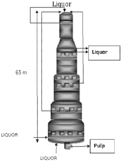
The pulping digester, shown in Figure 1, has a height of around 65 m and a diameter of 6 m at the top and of around 7 m at the bottom. The diameter increases stepwise from top to bottom.
Figure 1. The pulping digester.
The compressibility of the pulp arises as a result of the transfer of the lignin to the
liquid phase. The compressibility
contributes a unidirectional stream of liquor in the digester. The liquor is not evenly distributed throughout the chip bed, but forms channels through it. The liquor then follows the path of least resistance. The channel formation leads to some of the wood chips not having contact with the liquor. As a consequence, dissolution of lignin declines, a non-uniform cooking develops in the digester and the channel blocks the flow of the chips and disrupts
the process.
A heterogeneous porous media is specified in the digester model to represent the
3
compressibility of the solids.
Decomposition of the wood develops when lignin is removed from the chips. The chemical dissolution process makes the chips soft and more compact. In order to model the deformation of the wood chips, the digester is divided into small sections which contribute to define different porosities in these regions. In order to investigate the behaviour of the liquor as it moves down the chip bed, the prescribed porosities are highest at the top and reduce down the digester. The void volume between the chips is called the free liquor. As the lignin dissolves, the chip bed is compressed and the free space between the chips decreases. The volume fraction of the chips in the cooking blocks increases and the volume fraction occupied by the free liquor decreases.
Governing equations
The continuity equation for 2D axisymmetric geometries (mass conservation equation) m r r x S r v v r v x t ∂ + = ∂ + ∂ ∂ + ∂ ∂ ρ ρ ρ ρ ) ( ) ( (1)
Axial Momentum conservation equation for 2D axisymmetric geometries
X r x x x r r x F x v r v r r r v x v r x r r p v v r r r v v r x r + ∂ ∂ + ∂ ∂ ∂ ∂ + ∇ − ∂ ∂ ∂ ∂ + ∂ ∂ = ∂ ∂ + ∂ ∂
µ
µ
ρ
ρ
1 ) . ( 3 2 2 1 ) ( 1 ) ( 1 r (2)Radial Momentum equation
r z r r x r r r r x F r v v r r v v r v r r r r v x v r x r r p v v r r r v v r x r + + ∇ + − ∇ − ∂ ∂ ∂ ∂ + ∂ ∂ + ∂ ∂ ∂ ∂ + ∂ ∂ = ∂ ∂ + ∂ ∂ 2 2 ( . ) 3 2 2 ) . ( 3 2 2 1 1 ) ( 1 ) ( 1
ρ
µ
µ
µ
µ
ρ
ρ
r r (3)Porous momentum sink
Increased porosity reduces flow velocity due to generation of a pressure gradient in the cell zones. This is accounted for in the model by including an additional source term in the fluid flow equations. The source is a flow resistance and consists of two terms that are empirically determined. A viscous loss term and an inertial loss term are included in the momentum equation in the porous cell zones.
+
=
∑
∑
= = 3 1 3 12
1
j j ij j j ij iD
v
C
v
v
S
µ
ρ
(4) Turbulent kinetic energyK M b k i k t i i i
S
Y
G
G
x
k
x
ku
x
k
t
+
−
−
+
+
∂
∂
+
∂
∂
=
∂
∂
+
∂
∂
ρε
σ
µ
µ
ρ
ρ
)
(
)
(
(5)Turbulent dissipation rate
ε ε ε ε ε
ε
ρ
ε
ε
σ
µ
µ
ρε
ρε
S
k
C
G
C
G
k
C
x
x
u
x
t
b k j t i j j+
−
+
∂
∂
+
∂
∂
=
∂
∂
+
∂
∂
2 2 3 1(
)
)
(
)
(
(6) Reynolds number4
µ
ρ
ud=
Re (7)
Homogenous porous media
+ = i i i v C vv S ρ α µ 2 1 2 (8)
Darcy’s law in porous media
v
p
r
α
µ
−
=
∇
(9)Inertial loses in porous media
∑
= − = ∇ 3 1 2 2 1 j j ij v v C p ρ (10) Modeling set upA turbulent model and a heterogeneous porous media are defined for the digester. In the porous media the flow velocity decreases but generation of turbulence and the dissipation rate are still modelled through the media by the default approach in FLUENT. It is not necessary to restrict the turbulence in any zone in the porous media. In order to suppress the turbulence in any zone it is sufficient to activate the “laminar zone” in the fluid panel of that zone. In this way the turbulent viscosity (
µ
t) is considered zero in that section. The turbulence created in the porous media does not affect the momentum of the flow. The turbulent elements transport through the porous zones. The inertial loss term of the momentum sink is activated and specified for each porous section of the digester in both x and y directions. A porosity range is defined from 0.65 to 0.25, to account for the distribution of the fluid flow through the particles. Porosity value in the channels is 0.95. The length of top and down channels is respectively about 10 and 7 m. Channels include smaller channels in order to examine other channel size.The effect of gravity is taken into account and a value of 9.8 m/s2 is specified for gravitational acceleration in the positive x direction.
Results Channelling
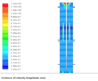
Figure 2: Contours of distribution of the Velocity inside the digester from top to bottom
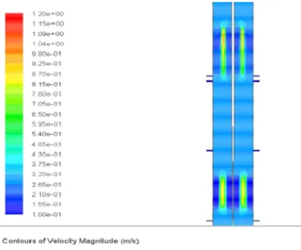
Figure 3: Contours of distribution of the Velocity at the top of the digester
5 Figure 4: Contours of distribution of the Velocity in
the two formed channels
Figure 5: Contours of distribution of the Velocity vectors at the entrance of the channel
Figure 6: Contours of distribution of the Velocity in the channel
Figure 7: Contours of distribution of the Velocity vectors around the outlet of the lower channel
Figure 8: Contours of distribution of the Velocity vectors around the outlet of the upper channel
Discussion
Due to the unique geometric design of the reactor, the heterogeneous reaction, the hydraulic characteristics of the zones, long residence time, and the multiple inlets and outlets it is not unreasonable to assume that different flow regimes are present in different zones within the digester. In some sections the flow is unidirectional and downward and in others the flow runs against this current. These unique characteristics contribute to the formation of a double flow regime in the digester.
6
Therefore, assigning an exclusive flow regime to characterize the digester is an ineffective approach. Multiple Reynolds numbers may be accounted for in the multiple inlets of the digester. The free liquor flow through the chips bed follows the laminar flow regime at the top and middle of the digester. Very low velocities are observed throughout the digester despite the high velocities at the inlets. This may be due to the solid phase, which is itself mobile, and leads to a momentum exchange with the fluid flow, and also behaves as a porous media for the liquid phase and considerably reduces its momentum. The Reynolds numbers at the inlets are defined at between 40000 and 70000. The inlet diameters are 0.35, 0.30, 0.20 and 0.16m. The viscosity is around 0.001 kg/m s
A k-ε turbulent model is defined due to the presence of the counter-current flow in the bottom of the digester which results in a turbulent regime. Applying a turbulent model contributes to the computation of small eddies in the lower zones of the digester.
The velocity of the liquor increases in the channels as shown by the “velocity magnitude” and “vectors of the velocity” in Figures 2 to 8.
When the liquor flow enters the channel its velocity increases due to the elimination of the momentum sink and the low amount of wood chips in the channels, as shown in Figures 2-4. When the liquor leaves the channel the velocity decreases again due to the presence of wood chips at its path, as shown in Figures 7 and 8. Inside the channel the velocity is higher at the beginning and decreases gradually as
shown in Figure 6. The velocity inside the channel has a negative gradient in the vertical direction. The reaction of the lignin and liquor takes place at high temperatures of above 150 °C. One study where the temperature of the washing screen was measured showed a large variation in its temperature before and after the channelling [8].
The model of the channelling can be used to locate the channels by comparing the operating parameters before and after channelling. Channelling affects operating conditions such as the outlet flow rate, pressure and temperature.
Any deviation of these parameters from the normal operational conditions may indicate channelling. However, the magnitude of the deviation that indicates channelling must be determined because the normal operating conditions are unsteady and only deviations over a certain magnitude may indicate channelling.
Conclusion
A pulping digester has been modelled to examine the destructive phenomenon of channelling. An artificial channel is modelled in the digester using a porous media model. A heterogeneous porous media is defined to represent the solid phase and its compressibility. Compared to a homogenous solid phase, using the heterogeneous solid phase has the effect of increasing the volume fraction of the liquid phase in the channel while reducing the porosity outside of the channel. The channels are characterized by defining a very high porosity in the digester.
The flow behaviour is examined around and inside the channel. The results of the
7
modelling show that the liquor velocity is higher inside the channel than outside it. This effect can affect the circulation flow in the pipes which may be an indicator of dangerous conditions.
The liquor velocity around the channel decreases and the circulation flows which are located along the channel degenerate. However, the mass flow rate in the circulation pipes under the channel would be expected to increase under these conditions. This can lead to a pressure drop in the pipes along the channel and an increased pressure in the pipes that are located under the channel.
These pressure changes are important parameters for the operation of the digester, and calculation of their magnitudes is an important topic for future studies.
Channel modelling improves our
knowledge of the hydraulic behaviour of the pulping digester which can assist in
diagnosis of dangerous operating
conditions and implementation of evasive action.
References
[1] Vroom, K, E, “The ´H´ factor: A means
of expressing cooking times and
temperatures as a single variable,” pulp and paper Mag. Can., Convention, Issue 1957
[2] C.C. Smith, T.J. Williams,
Mathematical modelling Simulation and control of the operation of kamyr continuous digester for Kraft process, Tech. Rep. 64, Purdue University, West Lafayette, USA (1974)
[3] Johansson L, Mathematical models of
the Kraft cooking process Acta
Polytechnica, Scandinavia Math. Comput. Mach. Ser. No. 22, Stockholm 1971
[4] R.R Gustafson, C.A. Slelcher, W.T. Mc Kean and B.A. Finalyson, Theoretical model of the Kraft pulping process, Ind. Eng. Chem. Process Des. Develop. 22 (1983)
[5] Tor Christinsen, Clifford C. Smith, Lyle F. Albright, T. J. Williams, Dynamic modelling of the Kamyr digester: normal operation including hardwood-softwood swings, Tappi J. vol. 66, no.11, (1983), p 65-68
[6] E.A. Harkonen, A mathematical model for two phase flow in a continuous digester, Tappi J. 70 (1987) 70(12) 122-126
[7] F.A. Michelsen and B.A Foss, Modelling and simulation of the mass flow and reaction kinetics in a continuous Kamyr steam/liquor phase digester, Modelling identification and control,1994, vol. 15, no.1, 33-53
[8 ]Toivonen, M., Optimization of the conditions in continuous cooking. Master thesis, Helsinki University of Technology, Finland, 2004. 60 p.