Master Thesis in Computer Science
With Specialization in Software Engineering
____________________________________________________________
Enhancing the consistency between
requirements and test cases through
the definition of a
Controlled Natural Language.
______________________________________ May 2015 Candidate:Valerio Lucantonio
MDH Supervisor: Examiner: UDA Supervisor:
Abstract
Requirements and testing engineering build up the solid base for developing successful software projects. In particular along the development process, testing follows and relies on requirements engineering: an incoherent specification of one of the two can affect the correctness of a project resulting in delays, failures, unhappy customers and other consequences on the project delivery.
Especially nowadays software companies are competing in fast changing markets where the delivery time of the products is the most crucial aspect and it really affects the quality and the success of the product. Given the semantic gap between requirements (typically written in natural language) and test specifications, it is not rare that requirements are misunderstood leading to erroneous tests. This risk is even more relevant when trying to perform early validation, since testing is mainly based on requirements definition.
This thesis work introduces an investigation to close the gap between requirements specification and test cases by providing automatic test case generation. Requirements are written in Natural Language, their subsequent restructuring in a more formal controlled natural language, and the final automatic translation derives test cases. The soundness of the concept is demonstrated through a practical implementation tailored to a previous real project developed at MDH. The implementation not only demonstrates the feasibility of the idea, but also shows interesting results in terms of generated test cases against the ones obtained for the project by hand.
Acknowledgement
I would like to give a special thanks to my supervisor at MDH Antonio Cicchetti for his endless support and encouragement during the whole thesis process. I would like to thank my parents and all my family for backing me up continuously during my life, encouraging me always to do my best. I would like to give a special thanks to my beautiful flower Serena for her patience and goodness during these years spent together. I would like to thank Genew Team for these years studying and supporting each other always together as brothers. I would like to thank all my real brothers and sisters: Tazza, Mirko, Marta, Charlie, Miky, Giuly to be always by my side regardless of the distance between us. Finally, a big thank to my GSEEM’s mates Giulio and Pina for the time spent together fighting against bureaucracy and exams. Last but not the least a special thanks goes to my Erasmus friends: Matej, Miguel, Gina, Betty, Gordo, Benny, Toni, Gabriele thanks for everything we made together, you are the best.
Index Of Figures:
Figure 1: Software Development Life Cycle ... 14
Figure 2:The V model ... 15
Figure 3:The Spiral Development Process... 16
Figure 4: User vs. System Requirements [5] ... 17
Figure 5:Spiral view of RE process [5] ... 19
Figure 6:Data Driven data file [16] ... 25
Figure 7: Keyword Driven data file [16] ... 25
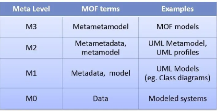
Figure 8: MOF architecture ... 27
Figure 9: Ontograph example [23] ... 35
Figure 10: The process of model-based testing [25] ... 36
Figure 11: Concept approach from specification written in NL to test cases (or test scripts) 41 Figure 12: Relation between PENS properties. White dots represent natural languages, black dots represent formal languages and blue dots represent CNLs (or CNLs classes). [20] ... 43
Figure 13: First specification words and occurrences ... 50
Figure 14: Second Specification parsed words ... 52
Index Of Table
Table 1 Codes for CNL Properties ... 29Table 2: PENS classes ... 31
Table 3: Classification of CNLs according with PENS classes ... 32
Table 4: : existing CNLs classified by Kuhn in [20] according with their properties ... 44
Table 5: Test Cases template of previous project treated as example. ... 58
Table 6 Delete Booking: original manual test case of previous project for requirement #2 .. 59
Table 7:Book Simulator: original manual test case of previous project for requirement #1 .. 60
Abbreviations List:
ACE: Attempto Controlled English BX: Bidirectional Transformation CNL: Controlled Natural Language
DRS: Disclosure Representation Structure GUI: Graphical User Interface
MDE: Model Driven Engineering NL: Natural Language
PENS: Precision Expressiveness Naturalness Simplicity RE: Requirements Engineering
SDLC: Software/System Development Lifecycle SRS: Software Requirement Specification SUT: System Under Test
TTM: Time To Market
UML: Unified Modeling Language MBT: Model Based Testing
Summary
1. Introduction ...8 1.1 Motivations ...8 1.2 Thesis Contribution ...9 1.3 Research Method ...101.3.1 Concrete Search Parameters...11
1.4 Outline ...12
2 Background ...13
2.1 Software Development Lifecycle Models ...13
2.1.1 Sequential Models ...14
2.1.2 Incremental Models ...15
2.1.3 Evolutionary Models ...16
2.2 Software Requirements Engineering ...17
2.2.1 Requirement Characteristics ...17
2.2.2 Requirements Validation...19
2.2.3 Towards Requirements Formalization ...20
2.3 Software Testing Engineering ...21
2.3.1 Testing Techniques ...22
2.3.2 Manual Testing ...23
2.3.3 Towards Automated Support ...23
2.4 Model Driven Engineering ...26
2.4.1 Models ...26
2.4.2 Metamodels ...27
2.4.3 Transformations ...27
3 State Of The Art ...29
3.1 Requirements Ambiguity Avoidance ...29
3.1.1 Controlled Natural Language ...29
3.1.2 CNL Frameworks ...34
3.2 Testing Automation ...37
3.2.1 Model-Based Testing ...37
3.2.2 Scenario Based Testing...40
4 Concept...43
4.1 Natural Language Requirement Specification ...43
4.2 Definition of a CNL and a Vocabulary ...44
4.2.1 Tradeoffs in CNLs ...45
4.3 Test Case Generation ...47
5 Case Study ...50
5.1 Requirements in NL ...50
5.2 Parsing Requirements in NL ...51
5.3 Definition of CNL and Vocabulary ...52
5.4 Mapping Requirements to Test Cases ...55
5.5 Test Cases Generation ...56
5.6 Automatic Approach vs Manual in Practice ...60
5.7 Conclusion ...63
6 Discussion ...64
7 Conclusions and Future Works ...66
8 References ...67 Appendix 1: ...70 Appendix 2: ...71
1. Introduction
Requirements engineering and testing represent the solid base for successful software projects. In software development, testing follows and relies on requirements engineering: an incorrect specification of one of the two can affect the project as resulting in delays, failures, unhappy customers and other consequences on the project delivery. Moreover, feedbacks of testing are often reflected on requirements in terms of refinements, additions or removals. Thus, collaboration and alignment between testing and requirements engineering are more than recommended, especially for complex software system development [3].
Testing represents a fundamental activity in software development, as it assures both reliability of the product and enriches the quality of the system itself. Specifying correct and complete test cases and ensure through their execution to cover all the existing requirements is a time consuming and error-prone task. The main reason is the gap between requirements specifications, typically formulated in non-formal notations, and tests. [4]
If testing cannot rely on well-defined requirements time will be wasted for interpreting and clarifying those requirements, and the mapping between requirements and corresponding test cases will be necessarily performed manually. Manual techniques on the one hand require a lot of human resources, and on the other hand make the testing frequently to be postponed too much during the development lifecycle [4].
In this scenario, specifying requirements through a formal language, different from the Natural Language (NL), would have the potentials of removing ambiguities in the specifications. Moreover, it would disclose the opportunity to create traceability links between requirements and corresponding test cases. These are currently two big challenges both in the software engineering research and in industry [9]. This thesis proposes to adopt controlled natural language (CNL) as an intermediate requirement definition mean, i.e. acting as a bridge between non-formal NL and automatically generated test cases.
1.1 Motivations
Software companies are now more than ever competing in fast changing markets where the demands of product and the delivery time is a crucial aspect and it really affects the quality and the success of the product. On the one hand testing is a fundamental activity which allows to deliver a well-defined and correct product. On the other hand it is a time consuming activity that affects software costs for the company and slows down the delivery of the product. Testing is usually performed at the end of the implementation, when costs for modifications are typically higher than in earlier stages of the development process [4]. In this respect, there has been a general effort targeting the revision of development processes in order to allow a more flexible kind of testing. There is a need of new testing techniques, and industries are slowly moving towards automated testing trying to use frameworks to speed up the testing process. Through these frameworks, it is possible to create test cases and to execute them on the System Under Test (SUT) in order to compare actual results with the expected ones. The
benefits of an automated approach are different, one of the most important is that the time to market is reduced sensitively. Indeed, automating testing can disclose the opportunity of starting the testing activity also before the implementation, and as a result it can allow saving time [9].
A precondition to make testing effective in general, and during the early stages of the development process in particular, is that requirements can be unambiguously interpreted and reflected to corresponding test cases. In turn, more precise requirements permit to introduce enhancements in the management of application evolutions by means of test cases traceability and change impact analysis [23]. Eventually, unambiguous requirements can disclose opportunities to (semi-)automatically derive test cases, thus introducing further consistency control in the development process.
The underlying main motivations for this works are therefore the need to speed up testing and a better quality of requirements that directly reflects in better test cases. In this way, requirements can be specified more formally granting a better test cases formulation, which, in turn, will reflect in increased software reliability as well as a short time to market.
1.2 Thesis Contribution
In order to enhance the consistency between requirements and test cases, this thesis work analyses different approaches for automating the definition of test cases as derivable from requirements specification. In particular, it investigates the traceability support between requirements written in Natural Language (NL), their subsequent restructuring in a more formal controlled natural language (CNL), and the final translation to appropriate concrete test cases. The objective discussed so far entails the following research questions:
RQ1: What are the state-of-the-art techniques to derive CNL from requirements definitions in NL?
RQ1.1 Are there any generic (i.e. non domain-specific) solutions? RQ2: How is it possible to automate the mapping between requirements and test cases through the exploitation of an intermediate CNL?
After investigating the state of the art on how derive a CNL from requirements written in NL I proceed with an investigation of any possible general approach to the definition of a CNL. Based on the result found at this point I evaluate any possible approach to map requirements, written in CNL form, to test cases in an automatic way. Through the application of the research method described in the next subsection, a clearer landscape of the state of the art is provided. In this respect, there is no an existing attempt that tries to cover the whole activities from requirements definition to test cases. Moreover, partial solutions available in the literature are very often domain-specific.
The knowledge gained in the survey is then exploited to formulate a concept, which aims at proposing a generic process for the automatic derivation of test cases from requirements specified through a CNL. Given the domain-specificity of the problem, it is not possible to propose a generic solution implementing the various steps that build-up the automatic generation. Therefore, the actualization of the concept is illustrated through a real case study: starting from a project requirements specification, I create the mapping solution, that consists of a dictionary with a CNL, and a transformation between requirements written according to the CNL and test cases defined according to a corresponding template. The case study has the scope to show the soundness and feasibility of the concept. Moreover, despite its relatively small size, the example demonstrates concrete relationships between test cases generated through requirements and tests effectively performed during the project.
1.3 Research Method
This thesis work has the goal to analyze current approaches for enhancing the consistency between requirements written in NL and test cases. The proposed solution relies on the definition of a CNL that on the one hand will ensure consistency between requirements and test cases, and on the other hand removes ambiguity in the requirements specification. In this respect, the thesis has involved both a state-of-the-art survey and some implementation work. For what concerns the research applied to this work, I started with a general search on testing and requirements of software systems through existing publications on international conferences, workshops and journals. This analysis gave me a better understanding on how the two phases (requirements and testing) could overlap in a development process and gave me the idea, developed in the concept, to formulate a general approach to reduce the gap (in terms of development time but also of consistency mechanism) between requirements in CNL and test cases.
Then I proceeded with the analysis of the state-of-the-art of CNLs related to software requirements specification. Through this analysis, I discovered that (to the best of my knowledge) there is no precise answer to the research questions RQ1 and RQ1.1. In particular the open problems related to RQ1 are that most of the examined CNLs are domain specific and not always in software engineering field. Moreover, they are often “embedded” in a tool, thus hindering the possibility of extrapolating general resolution guidelines. This analysis, although not completely successful, allowed me to narrow down the field of research according to precise constraints, defined later in this section. Moreover, it allowed me to propose a concept based on a CNL used in requirements specification as a support to the testing phase, and in particular to keep requirements and test cases consistent.
I investigated the state-of-the-art further in test automation by considering the automation starting from requirements written in NL (instead of CNL, since almost no work was compatible with the constraints applied to the search), and trying to apply/port available solutions in my setting, i.e. substituting NL with a CNL. From this analysis, being a CNL a subset
of a NL, it emerges that all the possible approaches devoted to the generation of test cases from requirements in NL are suitable for the CNL as well. Based on this fact, I could exclude the different kinds of test cases purposes from the concept, since the generation process can abstract from the specific intent as soon as a formal template describing test cases models is provided (analogously to NL).
Eventually, the concept has been formulated according to the material and knowledge gained in the analysis of the previous phases. It is concretized by the implementation of a prototype, based on a previous project done at MDH university. The realized prototype follows state of the art principles and techniques for the NL analysis, CNL template definition, test cases template specification, and CNL parser construction for deriving corresponding test cases.
1.3.1 Concrete Search Parameters
A generic query exploring the state-of-the-art related to requirements and test cases approaches would result in a huge amount of papers, with different scopes and prospective, that would be difficult to categorize in a meaningful way (for the scope of this work). Therefore, the research has to be guided and narrowed by the various aspects that characterize the topic. I introduced the following constraints:
1) Requirements specification has to be written in NL or CNL.
2) Test cases have to be generated from requirements specification. 3) The generation has to be automatic.
The databases chosen for the literature review are Google Scholar, IEEE Digital Library, and ACM Digital. Two queries have been formulated in each of the tree DB, for literature review: For RQ1 and RQ1.1:
("Controlled Natural language" OR "CNL") AND ("create" OR “generate from”) AND ("Natural Language" OR "NL") AND ("software specification" OR "software requirements" OR "software requirements specification") For RQ2: ("auto generate" OR "generate automatically” OR “auto derive” OR “automatically derive”) AND "test cases" AND "from" AND ("software requirements specification" OR “software specification” OR “software requirements”) AND (“natural language” OR "controlled natural language" OR “NL” OR “CNL”)
The queries generate 192 and 126 results, respectively. Moreover, articles published after 2005 have been considered at first (except for largely cited articles before 2005), published in English, that are composed of 6 pages or more, and are presented at least in a workshop. The resulting papers have been reduced, in order to select only significant papers, reading abstract, introduction and conclusions and deciding according to the contents if they are significant for the research. Among these results the research have been principally narrowed in the identification of 67 papers. From these papers the research has been guided from two main articles in the field:
• A survey and classification of controlled natural languages. T. Kuhn, (2014): a classification of more than 100 different CNLs representing the state of the art about
CNLs, the most cited publication in CNLs field with 47 cites. Through this article and the constraints defined to narrow the scope, it has been possible to reduce the amount of papers regarding the state-of-the-art of CNLs to 18.
• From Requirements Specification to Test Scripting: Towards Automated Support. R. Gustavsson, D. Kostopoulos(2014): a previous work realized at MDH suggested by the supervisor based on a side topic of this work thesis. Through the literature review in this work it has been possible to reduce the amount of papers for the state-of-theart in test automation to 29.
1.4 Outline
Section 2 provides a background in software development lifecycle (subsect. 2.1), requirements engineering (2.2), testing engineering (2.3) and model driven engineering (2.4). Section 3 concerns the state of the art of CNLs, as a requirement specification language (3.1), and testing automation (3.2) with related works (3.3). Section 4 describes the concept elaborated thorough the various subsections, from NL specification (4.1), to the definition of a CNL (4.2) and the generation of test cases (4.3). Section 5 contains an example applied to a previous project at MDH, supporting the concept in the various steps. At the end of the paper section 6 contains a brief discussion of the result of this work, and section 7 a small conclusion with possible future works.
2 Background
Contemporary software applications and services are commonly characterized by a competitive market, in which products have to be delivered in a fast way, because the demand of a product hardly depends on the Time-To-Market (TTM). This affects companies that have to modify their assets to be more competitive for the market, and this has been reflected in the adoption of new development processes. In particular, a typical strategy includes the introduction of a new stakeholder, the customer, who can strictly follow the development process and give suggestions and improvements to developers in order to shorten the delivery time and to enhance quality attributes. In such described scenario the importance of precise and well-defined requirements is evident since they affect directly the quality of the final product. Equally important, ambiguities in requirements definition can remarkably impact the delivery time.
This section explains different development lifecycles and illustrates software requirements engineering and software testing engineering.
2.1 Software Development Lifecycle Models
In software development the choice of an appropriate development process is one of the most delicate aspects to be treated. Indeed, the process provides a framework model to follow for all the activities involved in a software engineering project. A development process supports all the lifetime cycle and gives the precise standard and steps for the realization of the software. These steps, depicted in figure 1, can be summarized according to [2] by:
Requirement Analysis and Specification: The first step of this analysis is to get all the
requirements from the customers. Requirements are gathered, analyzed and formalized in a Software Requirement Specification (SRS) document that demarks the end of the requirements phase. This can in general also being not true, since, as we will see in the next subsections, requirements can change during the whole lifecycle.
Designing: Gathered all the requirements from the SRS they have to be translated in an
architecture with a precise design structure. The output of this phase is the design document.
Coding: The implementation phase, is when the specifications contained in the design
document are actually translated in code. The output of this phase is a software prototype.
Testing: The produced code is tested following different techniques, in order to evaluate the
correctness and validness of the software
Evolution and Maintenance: All the modification that can improve the product and all the
routines to ensure the correctness of the software system. This phase is responsible of the maintenance of the implemented system and the implementation of new features.
Figure 1: Software Development Life Cycle [36] 2.1.1 Sequential Models
Sequential models are one of the first development process used to approach software development. The foundation of this process is that every problem can be completely understood and formulated through a design software solution [1]. According to the development process life cycle model, a design formulation follows a requirements analysis and is followed by a design. All the implementation can be done before validation and testing. The characteristic of this model is that each phase strictly affects, upon its completion, the initiation of the next phase. The most referenced sequential model is the waterfall model, because it magnifies this tidy separation of the stages. The waterfall model is not a flexible development process especially for competitive markets. For this reason, the waterfall model evolved in more flexible models in order to support more competitive development.
This brought to one of the most used models, the V model. The V model is an evolution of the waterfall model, in a V shape as shown in figure 2. It is based on verification and validation of each phase of the process, so from the requirements analysis to the testing. The first part (left-hand side of the V) can be referred as Validation phase. It starts with requirements gathering and ends with detailed software design. At the bottom of the process there is the implementation phase. The right-hand side represents the Integration and Verification of the system components. It starts with unit testing and ends with user acceptance testing. It is worth noting that vertical axis also prescribe the level of the decomposition in modules of the system, and that each subcomponent can be developed using the V model process recursively [3]. In that particular case, as we will see in the next subsection, we can refer to the V model as an iterative development process.
The V model is widely adopted especially for safety critical systems, where it is important to define a strict process that assures that the actual product will meet safety requirements. In this kind of systems the interconnection between requirements and implementation is crucial. In order to have a strict control (traceability) over the activities of requirements definition and development of the system, the development process has to prescribe strict policies.
Figure 2:The V model [38]
2.1.2 Incremental Models
Iterative models can be seen as three-dimensional sequential model, where the number of sequential models in the z-axis specifies the number of iterations, or increments, that have to be made in order to improve system functionalities. One of the most important advantages, as Wallin and Land write in [1], is that “With incremental development lifecycle models, risk of
developing the wrong thing is reduced by breaking the project into a series of small subprojects (increments)”. This allows to have a faster feedback on system functionalities and at the same
time allows to respond faster to changes in requirements. One risk with the incremental approach is that the first releases address such a limited set of requirements that the customer could be dissatisfied, however keeping open the opportunity of fixing wrong or missing requirements on time. Moreover, using an iterative approach allows to involve new stakeholders at different times and iterations of the process, thus making the definition and refinement analysis of a particular functionality more effective.
Examples of incremental models are the staged-delivery and the parallel model. The former is characterized by the construction of a subsystem at a time, while the integration is performed indifferently at the end of the process or release-by-release. Instead, in the parallel development the subsystems are developed in parallel. In this way it is possible to shorten the TTM, although there could be problems in integration. Additionally, this development process doesn’t assure fast response on requirements changes.
2.1.3 Evolutionary Models
The border between incremental and evolutionary model is not really well defined, but we can definitely say that one of the biggest difference between them is that in the evolutionary models not all the requirements are available in the beginning of the process. For the remaining aspects, this process shares most of the characteristics with incremental models. One of the most used evolutionary model is the spiral development model, depicted in figure 3, defined by Boehm in [4] as:
”Spiral development is a family of software development processes characterized by
repeatedly iterating a set of elemental development processes and managing risk so it is actively being reduced.”
Another definition, always from [4], that stresses the relationship between spiral and the
other development processes is:
“The spiral model is actually a risk-driven process model generator, in which different risk patterns can lead to choosing incremental, waterfall, evolutionary prototyping, or other subsets of the process elements in the spiral model diagram.”
The spiral model is characterized by two properties: is a cyclic approach for incrementally
growing the system while decreasing its degree of risk. The other is a set of anchor point
milestones for ensuring stakeholder feedbacks. The evolutionary model’s disadvantage is that
it is complicated, indeed it is hard to plan and follow up and it might not be worth the effort using it if the development is manageable enough, with low risks. Another disadvantage is that the architecture of the first version of the system must support the changes introduced in each cycle. Otherwise, you will have to redesign your system completely, even though the experience acquainted from earlier cycles is very valuable input when doing this.
Figure 3:The Spiral Development Process [37]
2.2 Software Requirements Engineering
“The requirements for a system are the descriptions of what the system should do, the services that it provides and the constraints on its operation. These requirements reflect the needs of customers for a system that serves a certain purpose […]. The process of finding out, analyzing, documenting and checking these services and constraints is called requirements engineering (RE).”[5]
Requirements is the earliest phase of the development lifecycle. They state, independently from their implementation, the desired goals and achievements that the future software should reach. The main purpose of requirements engineering is to synthetize user requests in a clear, consistent, and unambiguous set of problem statements. For the sake of understandability and management, requirements are typically distinguished in the following two categories:
User Requirements: are statements written in a natural language with the use of some intuitive
diagrams. Their aim is to provide an initial system description in order to allow engineers to model them and to formulate a more formal specification that will be exploited during the entire development lifecycle.
System Requirements: are a more detailed description containing a full formulation of
features, services, and constrains that the final system must provide. The system requirements must provide an unambiguous formulation of the system to be implemented.
Figure 4 explains, through an example, the demarked difference between user and system requirements.
Figure 4: User vs. System Requirements [5]
2.2.1 Requirement Characteristics
Requirements engineering can be summarized in an iterative process, as shown in figure 5, starting from a feasibility study, followed by collection and analysis of requirements,
The duration of each phase is strictly dependent on the previous phase precision. At the end of the spiral a Software Requirements Specification (SRS) has to be released and each requirement in it can be considered as well-defined if it is:
Complete: means that there is not missing or to-be-determined information (also known as
internally completeness) and the information defined does not contain undefined referenced entities (or external completeness).
Correct: it is formally expressed by a combination of consistency and completeness.
Consistency refers to the attribute of not having contradictions while completeness refers to the point above. From a practical point of view, a correct requirement fully satisfies certain business goal [7].
Feasible: it is actually possible to satisfy the requirement considering its constrains, scenarios,
limitation and current budget.
Necessary: a requirement should be specified only if it contains information not contained in
other requirements, and can give an added value according to its expected functionalities.
Prioritized: each requirement should be prioritized, following a metric, in a way that engineers
are aware of its importance, and according to the stakeholders it is possible to make a plan based on this priority.
Unambiguous: this is a key aspect in requirements definition. The nature of the word
unambiguous does not assure anything to the engineers of the project, however it has to be clear that the requirement should not be understood in more than one way.
Verifiable: It is crucial for a project’s success to verify the expected behavior of the product.
Also this concept is very hard to apply in practice, as it basically prescribes that each requirement should entail a way to prove its satisfaction by testers, or even better, by test cases as we will see next.
This spiral can give the false perception that after the requirements document specification is released the requirements engineering process is completed. This is something not true in general, because requirements at the end of the product are usually slightly different from the ones in the beginning. As Kotonya and Sommerville say in [6]:
“The notion of ‘completeness’ in requirements definition is problematic. There is no simple
analytical procedure for determining when the users have told the developers everything that they need to know in order to produce the system required. Requirements are never stable. Changes in the environment in which the system has to work may change even before the system is installed, due to change in its operational environment.”
This can depend on many reasons, above all due to conflicts among stakeholders; indeed, it is not always easy to reach agreements and to write requirements in a formal way such that they mean the same thing for stakeholders with different backgrounds. Conflicts can depend from
everything: different user demands, changes in the business asset, additional constraints or other thousands of reasons.
Figure 5:Spiral view of RE process [5]
2.2.2 Requirements Validation
At the end of the spiral requirements should be validated in order to check that they actually define the system that the customer wants. The validation process allows to remove errors in requirements definitions, and to limit the cost of corrections during the development. This cost in fact, is much higher than repairing requirements right after their definition. The main reason is that changing afterwards often implies changing design architecture and implementation, and likely testing as well. According to Sommerville [5] the activities that have to be involved in the validation process have to be:
Validity checks: analyzing current requirements to understand if all the features required for
the system have to be specified through the specified requirements. In case, identify and add other requirements in order to specify new functions.
Consistency checks: there should be a clear and not-conflictual specification. Contradictions in
requirements should be erased and conflicting constrains analyzed and resolved.
Completeness checks: it is always worth trying to verify that requirements are complete,
although, as said before, it is not easy and there is no way of proving it formally.
Realism checks: using the state of the art of the technologies, the requirements should be
checked to ensure that they can actually be satisfied by a corresponding implementation. These checks should also take into account budget and schedule for the system development.
Verifiability: in order to reduce the gap between system and customer requirements,
requirements should be somehow verifiable. Therefore, it should be possible to demonstrate that the system released meets the requirements contained in the SRS.
In order to validate requirements different techniques have been proposed. Among them:
Requirements reviews: requirements are reviewed systematically by a team of reviewers who
check for errors and inconsistencies.
Prototyping: a prototype is implemented in order to give a real proof of the system. The end
user usually tests the system to verify that works according to the expected behavior.
Test-case generation: This is one of the key point of this thesis work, and it will be explained
better in the following subsections. The basic idea is that requirements should be testable. Testing the requirements is a good strategy to save efforts in the design phase of the system. Indeed, generating test cases from the requirements often uncovers problems in requirements, notably difficulties in the implementation and/or needs for clarification.
2.2.3 Towards Requirements Formalization
Writing requirements in the natural language (NL) is one of the most used approaches, both in research and in industry. The expressiveness offered by a natural language represents an added value to the definition, however it is high probable to have ambiguous, informal, and incomplete specifications. Several approaches have been introduced in order to mitigate the problems mentioned so far, and hence to obtain a more formal specification. Notably, in order to have a more structured approach, standard templates have been proposed such that requirements writers would use a subset of natural language in the writing procedure. This approach can limit the ambiguity of the requirements while at the same time granting expressiveness and understandability of natural language. A feasible template for a more formal requirements specification according with [5] should contain at least:
1. A description of the function or entity being specified. 2. A description of its inputs and where these come from. 3. A description of its outputs and where these go to.
4. Information about the information that is needed for the computation or other entities in the system that are used (the ‘requires’ part).
5. A description of the action to be taken.
6. If a functional approach is used, a pre-condition setting out what must be true before the function is called, and a post-condition specifying what is true after the function is called.
7. A description of the side effects (if any) of the operation.
The problem of having not well defined requirements using NL is well known, as well as the need for more formal designs on the way towards a complete implementation. These formal
requirements would support not only rapid prototyping of the desired software systems but could also provide a standard model upon which all successive implementations would be based on. Since object oriented modeling using UML and similar tools is a de facto standard for software system design, there is a need for a requirements specification language that might play an intermediate role between the original NL specification and a corresponding object-oriented design. One technique of object-oriented requirements engineering proposes to define the objects that will be used in the design by using the same nouns written in the requirements specification, and define the interactions among these objects as well as their operations using verbs and their objects [8]. The mapping between user requirements and system design is problematic and some additional tools can be used to facilitate the process. For a broader description of the approaches dealing with requirements specification the reader is referred to the state-of-the-art section.
2.3 Software Testing Engineering
“Testing is intended to show that a program does what it is intended to do and to discover program defects before it is put into use. When you test software, you execute a program using artificial data. You check the results of the test run for errors, anomalies, or information about the programs non-functional attributes.”[5]
One goal of software testing is to prove (to the developers but also to the client) that the software meets its requirements. This means that all the requirements must be tested at least once. A part of testing deals with validation, that is it is devoted to verify that the right system was implemented. In this case, based on the requirements specification, test cases will verify the system against expected inputs to show that it behaves as prescribed. Another goal of system testing it to discover errors, failures, and incorrect behaviors according to the requirements specification. This part copes with defect testing and aims at revealing imperfections. As a consequence, the test cases are built-up on all the possible inputs the system could receive.
It is clear that the border between the two kinds of testing is not really demarked and the activities often overlap. Indeed, during validation testing some errors may appear, and these are reflected to, and originate from, defects that will be discovered by defect testing.
Testing can be divided into two main classes, white box testing and black box testing. Black box testing consists of testing the whole application ignoring the source code and focusing only on the output that a test case gives in response to some input. White box testing, commonly referred as structural testing, is performed on the code, and test cases are conceived by taking into account the internal structure of the software. White box testing is mainly used for testing the code from a structural point of view, looking for dead or unreachable code, and checking all the possible branches and system states. Instead, black box testing is performed to test the features of the developed application.
A test case, as referred before is the definition of how a test can be performed on a desired feature. It contains a set of inputs, a set of (expected) outputs, pre and post conditions, and usually also more information about the failing and passing criteria. A test suite is a set of test cases, put together in order to specify a more complex scenario to test. Usually the test cases are divided into subsystems according to the functions and the structure of the application. Test cases then will be run with different approaches. At the end of the test running phase a document should be delivered, that reports all the information about the executed test cases and their outcomes.
2.3.1 Testing Techniques
Testing techniques are typically tailored to the used development process. We can summarize the different techniques in the following list:
Unit Testing: is a pure white-box testing approach based on low-level implementation. Unit
testing can be defined as the process of testing program components, such as methods or object classes [5]. Unit testing does not ensure to check all the functionalities of a program, rather it is used to guarantee that building blocks of the software work as a whole, independently from each other. It is performed by testers or engineers during the implementation phase of the software development lifecycle. Typically its goal is to test all the functions and the methods of a certain unit, therefore it usually exploits different inputs. Testing objects and classes implies the coverage of all their features, hence the operations within an object, object attributes (against their possible values), and all the possible statuses an object may acquire.
Integration Testing: depending on the used approach it can be either a black box or a white
box technique. Integration testing consists of testing more units combined in a larger component. Testing is done mainly on the interfaces of the units plugged together, in order to ensure that the communications between them have the correct behavior. Integration testing is done iteratively until all the units are integrated in a system that works as a whole.
System Testing: it is a black-box approach and is performed at the end of the software lifecycle.
After all the components are integrated together composing a version of the system, the whole software is tested to check that all the components are compatible and interact correctly exchanging the right input and output across their interfaces. The testing is usually performed by someone that does not know the internal details of the system, in order to ensure an unbiased procedure, closer to end users. This kind of interaction testing should discover bugs that are not revealed by the integration and unit testing. In system testing also performance and non-functional requirements should be proved.
Acceptance Testing: it’s a black box approach based on requirements specification and
performed at the end of the lifecycle, just before delivering the product. The main purpose of acceptance test is to provide an agreement (with the customer) on the developed system and deliver the final product. Therefore, it is mainly run in order to demonstrate that the system
works as required. The test suit is run with different inputs, and the outcomes are compared with the expected outputs. If the suite meets the expected results acceptance test is successful and the system can be delivered. Otherwise, the system is rejected and discovered bugs have to be fixed previous a new delivery attempt.
Regression Testing: it can be used either as a black box or a white box technique. In regression
testing a test suite is developed incrementally, while the program is developed. Hence it can be collocated across the implementation phase in the spiral lifecycle, but depending on which testing technique is applied it can be also in the design phase.
Essentially, this approach consists in rerunning all the existing test cases together with newer ones, introduced when units are joined together. In this way it is possible to check whether the integration process causes bugs or undesired states of the system.
2.3.2 Manual Testing
Manual testing is a widely used approach and consists of manually writing test cases using appropriate techniques. Testers write test cases manually: on the one hand testers’ skills and knowledge positively affects the efficacy of tests. In fact, it is scientifically proved that manually written tests entail very good results in terms of design and execution, especially in small projects. On the other hand, when the size and complexity of the software grow, it becomes more and more difficult to keep an acceptable quality level [10]. There are two main kinds of manual testing approaches [13]:
Code-Driven Testing: is a kind of white box testing and aims to test various sections of code to
verify if the system behaves correctly. Some frameworks, such as jUnit, xUnit, pyUnit, Gobo Eiffels, have been provided to support automation in test case execution. Test cases are written according to the technique chosen by the testers. The purpose of the test cases is to trigger a particular state or behavior in the object to assure that the outcome will be consistent with the expectations. Code Driven testing is usually used in agile development techniques and runs during the whole development process.
Graphical User Interface (GUI) Testing: Is a black box approach based on running the software
from the GUI interface simulating the user choices. Each time the system is run, the interaction is recorded for comparing the current outcomes with all the previous simulations. There are many tools providing record and playback features to interactively record the simulation. The big advantage of this method is that it does not require any specific knowledge in a testing environment, since it mainly consists of exploring the application from a user perspective. A disadvantage of this technique is that it is not possible to reuse previous test cases, since they are simple recordings.
2.3.3 Towards Automated Support
A notorious problem with software testing is its costs, both in terms of human resources and time. In fact, the growing complexity of software applications entails corresponding testing
efforts, and in a competitive market long testing phases collide with the general need of reducing TTM. As a consequence, manual testing appears to be a relevant bottleneck on the way of trying to optimize the validation and verification activities. Automating testing is a relevant topic both in research and industry, and is recognized as a valid approach for alleviating the problem of testing costs. The main idea is to support testing through the whole software development by automating the process. There are many approaches to provide test automation, and also a variety of software frameworks to support the activity. According to [14] three of the most used approaches to test automation are Capture/Playback, Data-Driven, and Keyword-Driven. The selection of the approach to use for automation is based on different parameters, notably testers’ skills, the development phase in which the testing process is placed, and others.
Capture/Playback: This can be seen as the manual GUI testing, but with the big difference that
the actions are captured in background by a tool; in this way, it is possible to record also the testing activities to enable test cases reuse. So this approach relies more on test scripts that the GUI approach, although the recording features are performed from a GUI point of view. Therefore, testing is firstly executed manually, to create a test scenario, and then recorded in order to re-execute them for verifying the correct behavior of the system after some changes. Capture and playback tools usually work on a more abstract level of the system to increase portability and enable the definition of test scenarios, i.e. the recording of general browsing actions instead of mouse actions. Nevertheless, this does not guarantee that changing the structure of the GUI will leave the tests valid and reusable without any modifications [15]. As suggested in [13], there are many advantages and disadvantages of using this testing technique: a big advantage is that there are no major requirements of particular technical skills for performing this kind of testing, but at the same time this approach is not fully automatic, since it requires manual emulation (at least once). Another advantage of capture and playback approaches is that tests do not need to be written in advance, indeed they can be developed on the fly. However, they require the system to be stable in order to be testable, otherwise there could be the problem of having to redefine the same test multiple time, even for small changes.
Data Driven: The main idea of data driven testing is to use a capture/playback approach but
to test the application with variable input and output. This approach leads to a problem caused by having inputs and outputs together within the test script, which means that every time data need to be updated the test script has to be regenerated or at least changed. This can cause problems especially if who is updating testing data is not aware of the test scripts. For huge systems embedding data into the test scripts is not a viable alternative, therefore they are typically read from another file input of the script. Hence, inputs and expected outputs are contained in an extern file, while the definition of the test script is contained in another file. The file containing the data, as in figure 6, is typically a table or spreadsheet or in a format that is easy for testers to be understood. Among those formats the most diffused are CSV (Comma Separated Values), TSV (Tab Separated Value), HTML tables and others
[16]. As a consequence, there exist also a lot of tools for editing raw data in these formats. Another convenient and scalable approach to manage test data is to let the script read them
from a database. In this way, testing data can be shared across the whole organization, or the part of it dealing with testing activities.
Figure 6:Data Driven data file [16]
Keyword Driven: is based on data driven testing, hence the logic of the test script stays
separately from the data. This test aims at alleviating one of the problems of data driven testing, that is some test cases might be very similar, but require in any case different test scripts. By means of the keyword driven approach data can contain also directives to provide some malleability to test scripts. In particular these directives, called keywords (see figure 7), affect the behavior of a test script by controlling the actions required case-by-case.
Figure 7: Keyword Driven data file [16]
2.4 Model Driven Engineering
When talking about automatic processes it has to be involved at least the notion of Model Driven Engineering (MDE). MDE is based on the principle of abstracting a real phenomenon, i.e. the system under study, in order to reduce the complexity of its development. Indeed, in a code-centric approach the quality of the final software application relies on programmers’ skills. In order to reduce costs and TTM improving the quality of the software, MDE introduced a new vision of software development that shifted the focus from coding to modeling. Therefore, the central idea of MDE is move towards a model-centric approach for realizing software systems. The first immediate benefit of working with models instead of code, is the reduction of complexity thanks to the representation of the system from a more abstract level. Moreover, the use of models discloses the opportunity to automatically generate implementation code from system design, through an automated procedure called model transformation. The MDE vision is based on the definition of three main entities: models, metamodels and transformations.
2.4.1 Models
A model represents an abstraction of the reality, in the sense that it represents those aspects that are relevant for the system under development. In this respect, an abstraction cannot represent all the details of the reality, but only those pertaining to the purpose a model is used for.
In the software engineering field, the most widespread modeling language is Unified Modeling Language (UML). UML offers a way of designing the system using some blueprints called diagrams or models that include activities, entities of the system, interactions among them, and many others. UML, as all the modeling languages, has the purpose to simplify the design process in software development. Usually it is possible to distinguish different kinds of models or diagrams depending on the perspective from which a the system is observed:
Static Diagrams: static diagrams point out the structure of the system using objects, attributes
and operations on these objects. Static diagrams allow to divide the system in more separated entities that can be subsystems or simply basic entities of the system.
Dynamic Diagrams: dynamic diagrams allow to describe the system from a behavioral point of
view. This is done specifying collaborations, and relations between the objects defined in the static diagrams. Through dynamic diagrams it is possible to specify how the system entities interact with each other and allow to simulate system’s scenarios specifying possible activities, states and sequence of actions.
2.4.2 Metamodels
In order to build-up a model, it is necessary to specify what aspects of a certain reality it is going to contain. In this respect a key concept is represented by the metamodel. In fact, a metamodel specifies a set of rules that identify how a model should be built for representing a certain real phenomenon. In other words, a metamodel prescribes what are the concepts and the relationships among them to describe a system. A model is said to conform to a metamodel when the former adheres to the rules the latter imposes. Given the flourishing of multiple technological solutions and frameworks for realizing the MDE vision, the Object Management Group (OMG) decided to define a standard framework for MDE. This standard encompasses the UML, and a minimal set of concepts exploited to define metamodels. This set of concepts is technically known as the meta-metamodel, and has been standardized under the Meta Object Facility (MOF) name [17]. The standard also carries by a well-defined metamodelling architecture, represented in figure 8, partitioned in four layers. The highest level, M3, represents MOF, i.e. the tool to build metamodels, which are located on level M2. An example of M2 metamodels is UML metamodel. Metamodels allow to specify models, which pertain to level M1. So in the case of UML M1 models are UML models like class diagrams, use case diagrams and so on. The last layer, M0, corresponds to the real object or system.
Figure 8: MOF architecture 2.4.3 Transformations
The main principle behind MDE is to move from a code-centric to a model-centric approach. In this respect, it is of critical importance that models can be automatically manipulated by computers to generate other artifacts (at least code that should be derived by hand otherwise). Moreover, the growing adoption of MDE promoted the exploitation of models for other tasks, notably analysis and documentation. MDE prescribes the use of transformations as the mean to operate on models. In other words, a transformation is a program that converts a model, referred as the source, in another model, called target. It is worth noting that the mapping between the source and the target is not established at model level (M0), rather the elements of the source metamodel are mapped towards corresponding elements in the target metamodel. Hence the transformation is specified through a set of rules that operate a conversion from a source to a target model, both of them conforming to their respective metamodels. So the transformation guarantees that a legal input model is mapped towards an appropriate legal output. When the transformation operates only on a specific direction it is referred to as unidirectional transformation.
In some situations there could be the need to perform a mapping in both the directions, so from source to target and vice versa. Bidirectional transformations born with the idea of supporting such kind of needs. Notably, bidirectional transformations (BX) provide a way to ensure consistency between two models, so when one changes (being the source or the target) the other can be synchronized accordingly [18].
3 State Of The Art
This section contains a survey of the most common practices available in the literature about the core aspects of this thesis work. The objective is to give an overview of the CNLs field; in particular, I illustrate those works aiming at a better formalization of requirements for allowing the generation of consistent test cases through automation testing techniques. The intention of this survey is to illustrate existing solutions to the problems involved in the overall goal of this thesis, and hence to provide a general understanding of the issues and related countermeasures in mapping requirement specifications to test cases. In this respect, in the following I first introduce techniques for disambiguating requirements definitions that culminate with CNLs, and then I present available mechanisms for the provision of automation support to testing activities.
3.1 Requirements Ambiguity Avoidance
In defining requirements natural language is among the most common adopted solutions, mainly because it is fully understandable (even by non engineers/technicians), universal and flexible, and it gives to the requirements a high level of expressiveness. Unfortunately, NL is intrinsically ambiguous and requirements can be easily misunderstood if specified with it. This is a big problem especially considering that very often stakeholders are not aware of ambiguity in requirements definition [19]. To alleviate the ambiguity problem engineers proposed different solutions and approaches, based on the general goal of seeking the right tradeoff between higher degree of formality and expressiveness of the language. Although there are different tools and frameworks that help to remove ambiguity in requirements, there is no standard solution to this problem. The introduction of a Controlled Natural Language represents a solution in the direction mentioned above, that is having a more formal requirements definition approach while still keeping high expressiveness of the language.
3.1.1 Controlled Natural Language
One of the solutions proposed to remove ambiguity in requirements definition is the Controlled Natural Language (CNL). CNLs are a set of engineered languages based on vocabularies, expressions, grammatical constructions, and semantic interpretations, written in a natural language such as English [19]. They facilitate human to human communication helping in requirements analysis and documentation over the lifecycle, and human to machine communication specifying for example the interfaces between components or the APIs for a database connection. CNLs are derived from natural languages, therefore specifications can be written in an easy, readable, and understandable format such that they offer more expressiveness than other technical domain specific languages. According to Kuhn [20], a language is called CNL if it respects the following properties:
• It is based on one and only one natural language (basic language).
• It should keep the natural properties of its base language, hence ensuring its usability, understandability also for stakeholders of different domains.
• It is a constructed language, which means that it is well defined on solid constructs always specified. This means that implicit definitions are not accepted, as well as natural processes.
CNLs are supposed in the one hand to solve issues derived from communication among stakeholders (speaking different native languages) providing a natural representation for formal specifications, and on the other hand to give an approach to translate a natural language in a language that machines can recognize, in order to trace requirements documentation. Moreover, a CNL can be useful even to write documentation, and as a medium in verbal discussions. Depending on the usage of the CNL, it can be domain specific, or general purpose, and according to the domain, it can be written in and for different contexts such as academia, industry, or government.
Property Code Comprehensibility C Translation T Formal Representation F Written Language W Spoken Language S Narrowed Domain D
Generated from Academia A Generated from Industry I Generated from Government G
Table 1 Codes for CNL Properties
Table 1, defined by Kuhn in [21], shows the properties of CNLs based on problems they address (comprehensibility hence for humans, or translation hence for automatic generation of artifacts), mode of usability (written or spoken), origins (academia, industry or government), and whether it is general purpose or domain specific CNL. However, these properties are not enough to describe a CNL: indeed, a CNL is based on a natural language, so all the properties of a natural language can be added to a CNL to enrich and characterize it. Furthermore, these properties are more oriented to the domain of application rather than to the language itself. In order to narrow down and shorten these properties a better classification, in which some properties are merged together, has been proposed. According with the authors in [20], CNLs can be characterized by means of the so called PENS classification schema, which is composed by four properties of a language:
Precision: it comprises the degree level of ambiguity, predictability and formality. NL does not
context has to be specified. On the contrary, formal languages enjoy higher precision, because their meaning is unique and well defined.
Expressiveness: it gives the range of expressions that is possible to reach using a language. In
other words, it is the size of all the possible concepts that can be expressed using a certain CNL. PENS classification scheme uses the following five features:
1) Universal quantifiers
2) Relations of arity greater than 1 3) Structured rules
4) Negation
5) Second-order universal quantifiers
Naturalness: represents the degree of the look-and-feel and understandability of the CNL. In
other words, it describes how much the CNL is close to its basic language.
Simplicity: represents the simplicity or complexity of a language taking into account its syntax
and semantics. It can be considered as the effort needed to write the language syntax in a mathematical algorithm. As indicators of simplicity the PENS scheme can rely on the number of pages needed to describe the language itself.
PENS uses a natural language and a formal language to define a range of possible CNLs created by mixing together the two languages. Each CNL in the range is obtained by giving a class, from 1 to 5, to each of the properties in PENS. The five classes do not overlap each other because they are fully and properly defined. Table 2 contains on the x axis the PENS properties, and on the y axis the five classes. Referring to table 2, for example English language has class 1 for precision and simplicity (P1 and S1), Propositional logic instead is in the opposite class for these two properties, being in P5 and S5. For expressiveness and naturalness it happens the contrary: English is in class 5 (E5 and S5) whereas propositional logic is in class 1 (E1 and S1). By following this example it is possible to classify all the CNLs on a scale containing 54 = 625 classes. Each class is represented by its formula given by the PENS properties classes. Always taking into account the previous example, English is P1E5N5S1 [20].
Precision Expressiveness Naturalness Simplicity
1 Imprecise Languages: Vague and ambiguous sentences.
Complex sentences are ambiguous.
Inexpressive languages: One or both the features 1) and 2) are missing. Propositional logic belongs to this category.
Unnatural Languages: Heavy use of symbols, characters, brackets, or unnatural keywords. Natural phrases are possible but not required.
Very complex: Have the complexity of NL.
Cannot be described exactly.
![Figure 1: Software Development Life Cycle [36]](https://thumb-eu.123doks.com/thumbv2/5dokorg/4812129.129455/14.892.306.591.111.403/figure-software-development-life-cycle.webp)
![Figure 2:The V model [38]](https://thumb-eu.123doks.com/thumbv2/5dokorg/4812129.129455/15.892.147.706.135.529/figure-the-v-model.webp)
![Figure 3:The Spiral Development Process [37]](https://thumb-eu.123doks.com/thumbv2/5dokorg/4812129.129455/16.892.248.702.806.1023/figure-the-spiral-development-process.webp)


![Table 3: Classification of CNLs according with PENS classes [20]](https://thumb-eu.123doks.com/thumbv2/5dokorg/4812129.129455/34.892.89.783.106.235/table-classification-cnls-according-pens-classes.webp)
![Figure 9: Ontograph example [23]](https://thumb-eu.123doks.com/thumbv2/5dokorg/4812129.129455/36.892.210.696.740.1111/figure-ontograph-example.webp)
![Figure 10: The process of model-based testing [25]](https://thumb-eu.123doks.com/thumbv2/5dokorg/4812129.129455/38.892.264.634.99.531/figure-process-model-based-testing.webp)

