Dept. of Microelectronics and Information Technology (IMIT)
Stockholm, Sweden
Universidad Politécnica de Madrid (UPM)
Facultad de Informática (FI)
Madrid, Spain
Secure Mobile Voice over IP
Master of Science Thesis
June 2003
Student:
Israel M. Abad Caballero
Supervisor at KTH / IT:
Professor Gerald Q. Maguire Jr.
Supervisor at FI UPM:
Professor Pedro Gómez−Vilda
Abstract
Voice over IP (VoIP) can be defined as the ability to make phone calls and to send faxes (i.e., to do everything we can do today with the Public Switched Telephone Network, PSTN) over IP−based data networks with a suitable quality of service and potentially a superior cost/benefit ratio.
There is a desire to provide (VoIP) with the suitable security without effecting the performance of this technology. This becomes even more important when VoIP utilizes wireless technologies as the data networks (such as Wireless Local Area Networks, WLAN), given the bandwidth and other constraints of wireless environments, and the data processing costs of the security mechanisms. As for many other (secure) applications, we should consider the security in Mobile VoIP as a chain, where every link, from the secure establishment to the secure termination of a call, must be secure in order to maintain the security of the entire process.
This document presents a solution to these issues, providing a secure model for Mobile VoIP that minimizes the processing costs and the bandwidth consumption. This is mainly achieved by making use of high− throughput, low packet expansion security protocols (such as the Secure Real−Time Protocol, SRTP); and high−speed encryption algorithms (such as the Advanced Encryption Standard, AES).
In the thesis I describe in detail the problem and its alternative solutions. I also describe in detail the selected solution and the protocols and mechanisms this solution utilizes, such as the Transport Layer Security (TLS) for securing the Session Initiation Protocol (SIP), the Real−Time Protocol (RTP) profile Secure Real−Time Protocol (SRTP) for securing the media data transport , and the Multimedia Internet KEYing (MIKEY) as the key−management protocol. Moreover, an implementation of SRTP, called MINIsrtp, is also provided. The oral presentation will provide an overview of these topics, with an in depth examination of those parts which were the most significant or unexpectedly difficult.
Regarding my implementation, evaluation, and testing of the model, this project in mainly focused on the security for the media stream (SRTP). However, thorough theoretical work has also been performed and will be presented, which includes other aspects, such as the establishment and termination of the call (using SIP) and the key−management protocol (MIKEY).
Sammanfattning
Voice over IP (VoIP) kan defineras som förmågan att göra ett telefonsamtal och att skicka fax (eller att göra allting som man idag kan göra över det publika telefonnätet) över ett IP−baserat nätverk med en passande kvalitet och till lägre kostnad, alternativt större nytta.
VoIP måste tillhandahållas med nödvändiga säkerhetstjänster utan att teknikens prestanta påverkas. Detta blir allt viktigare när VoIP används över trådlösa länktekniker (såsom trådlösa lokala nätverk, WLAN), givet dessa länkars begränsade bandbredd och den bearbetningkraft som krävs för att exekvera säkerhetsmekanismerna. Vi måste tänka på VoIPs säkerhet likt en kedja där inte någon länk, från säker uppkoppling till säker nedkoppling, får fallera för att erhålla en säker process.
I detta dokument presenteras en lösning på detta problem och innefattar en säker modell för Mobile VoIP som minimerar bearbetningskostnaderna och bandbreddsutnyttjandet. Detta erhålls huvudsakligen genom utnyttjande av säkerhetsprotokoll med hög genomströmning och låg paketexpansion, såsom "Secure Real− time Protocol" (SRTP), och av krypteringsprotokoll med hög hastighet, såsom "Advanced Encryption Standard" (AES).
I detta dokument beskriver jag problemet och dess alternativa lösningar. Jag beskriver också den valda lösningen och dess protokoll och mekanismer mer detaljerat, till exempel "Transport Layer Security" (TLS) för att säkra "Session Initiation Protocol" (SIP), SRTP för att skydda transporten av data och "Multimedia Internet KEYing" (MIKEY) för nyckelhantering. En implementation av SRTP, kallad MINIsrtp, finns också beskriven.
Beträffande praktiskt arbete och tester av lösningsmodellen har detta projekt fokuserats på skyddandet av datatransporten (SRTP), dess implementation och prestanda. Emellertid har en grundlig teoretisk undersökning genomförts, vilken innefattar andra aspekter såsom telefonsamtalets uppkoppling och nedkoppling (med hjälp av SIP) och valet av passande nyckelhanteringsprotokoll (MIKEY) för att stödja SRTP.
Preface
This work has been performed as a degree project at Telecommunication Systems Laboratory (TSLab), Department of Microelectronics and Information Technology (IMIT), Kungl Tekniska Högskolan (KTH), Stockholm, Sweden, during the period February 2003−June 2003.
I would like to express my sincere thanks to:
Prof. Gerald Maguire, my supervisor at KTH, for his help, his encouragement, his suggestions, and the opportunity he gave me of joining IMIT for developing my degree project;
Jon−Olov Vatn, for all his inestimable help, his patient, his continuous encouragement, his suggestions, and his kindness;
Erik Eliasson, for his help to develop MINIsrtp , his permission to use MINISIP and MIKEY source code, and for his ideas and suggestions for the project;
Prof. Pedro Gómez−Vilda, my supervisor at FI UPM, for his support and the opportunity he gave from my home university of studying at KTH;
all the friends who were near me during my stay in Stockholm, specially Álvaro, Jürgen, and Nacho.
A special thank to my parents, who gave me the opportunity of coming and studying here in Stockholm , and always support my decisions. To my family and friends, that took care of me from Spain during my stay here. To Miguel, my brother, one of my best friends and one of my strongest supports. And specially to Rocío, for all the love she gave me during this year, and without whose continuous support and infinite patient this would not have been possible.
Other acknowledgements:
Petra Rubalcaba (FI UPM); Elisabetta Carrara (Ericsson); Mark Baugher and David McGrew (Cisco Systems, Inc.); Aaron Gifford; Johan Bilien; Jürgen Prokop for his help with Figure 5.5; Professor Jean− Jacques Quisquater and the Microelectronics Laboratory Crypto Group (Université Catholique de Louvain, UCL), for their permission for using Figure 5.3.
The source code shown in this document that is copyright protected by Erik Eliasson (TSLab, IMIT, KTH) appears with his permission.
Figure 5.3 appears in this document with the explicit permission of Professor Jean−Jacques Quisquater, Microelectronics Laboratory − Crypto Group, Université Catholique de Louvain (UCL).
Table of Contents
Abstract ... i
Sammanfattning ... ii
Preface ... iii
1. Introduction ... 1
2. Voice Over IP Overview ... 3
2.1 Introduction ... 3
2.2 Components, Protocols, and Standards ... 3
3. Introduction to SIP and RTP ... 6
3.1 Session Initiation Protocol (SIP) ... 6
3.1.1 Introduction ... 6
3.1.2 Functionality ... 6
3.1.3 SIP Requests and Responses ... 8
3.2 Real−Time Protocol (RTP) ... 9
3.2.1 Introduction ... 9
3.2.2 Terminology and Definitions ... 10
3.2.3 RTP Packet Format ... 10 3.2.4 RTCP Packet Format ... 11 4. Security Services ... 13 4.1 Security Attacks ... 13 4.2 Authentication ... 14 4.3 Access Control ... 14 4.4 Data Confidentiality ... 14 4.5 Data Integrity ... 15 4.6 Non−Repudiation ... 15 4.7 Availability ... 15 5. Cryptography Overview ... 16 5.1 Basic Knowledge ... 16 5.1.1 Introduction ... 16 5.1.2 Symmetric Cryptography ... 17 5.1.3 Asymmetric Cryptography ... 18
5.1.4 Symmetric Cryptography vs. Asymmetric Cryptography ... 19
5.1.5 Cryptanalysis ... 19
5.1.6 One−way Hash Functions and MACs ... 20
5.1.7 Overview of the Hash−based Message Authentication Code: HMAC 21 5.1.8 Certificates ... 21
5.1.9 Location of encryption devices ... 22
5.2 Basic Algorithm and Methods ... 22
5.2.1 Advanced Encryption Standard (AES) ... 22
5.2.1.1 AES History ... 22
5.2.1.1 Overview of the Algorithm ... 22
5.2.2 Data Encryption Standard (DES) ... 25
5.2.3 Secure Hash Algorithm (SHA) ... 25
5.2.3.1 Overview of the Algorithm ... 25
5.2.4 Hash−Based Message Authentication Code ... 27
6. Public−Key Infrastructures ... 29
6.1 Introduction and Terminology ... 29
6.2 X.509 Certification Infrastructure ... 29
6.2.1 Chaining ... 31
6.2.2 Revocation of Certificates and Certificate Revocation Lists (CRLs) 31
6.3 Certification Infrastructure Models ... 33
7. Introduction to Security Protocols and Related Protocols ... 36
7.1 Internet Protocol Security (IPSec) ... 36
7.1.1 Introduction, Applications, and Benefits of IPSec ... 36
7.1.2 IPSec Architecture ... 37
7.1.2.1 IPSec Transport and Tunnel Modes ... 37
7.1.2.2 Authentication Header (AH) ... 38
7.1.2.3 Encapsulating Security Payload (ESP) ... 39
7.2 Transport Layer Security (TLS) ... 40
7.2.1 Introduction, Applications, and Benefits ... 40
7.2.2 SSL/TLS Architecture ... 40
7.2.2.1 SSL/TLS Record Protocol ... 40
7.2.2.2 SSL/TLS Handshake Protocol ... 42
7.3 Key Management Protocols ... 44
7.3.1 Introduction ... 44
7.3.2 IKE / ISAKMP ... 45
7.3.3 Simple Diffie−Hellman Key Exchange ... 45
8. Objective: Enabling a Secure Mobile VoIP call ... 47
9. Mobile Voice over IP: The Model and its Components ... 49
9.1 Significant Components ... 49
9.1.1 Mobile Nodes ... 49
9.1.2 SIP Servers ... 50
9.1.3 DSN Servers ... 50
9.2 The SIP Trapezoid ... 50
9.3 The SIP Registration ... 51
9.4 The RTP Session ... 51
9.5 Other Components ... 51
9.5.1 Home Agents ... 52
9.5.2 AAA Servers ... 52
9.5.3 Access Points ... 52
10. Alternative Solutions for Secure Mobile Voice over IP ... 54
10.1 Security Requirements of the Model ... 54
10.2 Securing SIP ... 55
10.2.1 Using SSL/TLS in a PKI ... 56
10.2.2 Using IPSec ... 57
10.2.3 Securing SDP Bodies and SIP Headers ... 58
10.2.4 Securing the DNS look−up ... 58
10.2.5 Conclusions ... 58
10.3 Securing the media stream ... 59
10.3.1 Secure Transport Protocol ... 59
11. A Secure Model for Mobile Voice over IP ... 61
11.1 Overview of the Model ... 61
11.2 Interoperation of the Components ... 62
11.3 Rationale ... 63
11.3.1 TLS supported by a PKI ... 63
11.3.2 DNSSEC ... 63
11.3.3 The User Agent: MINISIP ... 64
11.3.4 SRTP vs. IPSec and VPNs ... 64 11.3.5 MIKEY ... 64 12. SIP Security ... 65 12.1 Background ... 65 12.2 TLS within SIP ... 65 12.3 A First Approach ... 66
13. Secure Real−Time Protocol ... 67
13.1 SRTP Description ... 67
13.1.1 SRTP Packet ... 67
13.1.2 SRTCP Packet ... 69
13.1.3 Message Authentication and Integrity ... 70
13.1.4 Key Derivation ... 70
13.1.5 Cryptographic Context ... 71
13.1.6 Packet Processing ... 71
13.1.7 Predefined Algorithms ... 71
13.1.7.1 Encryption ... 72
13.1.7.2 Message Authentication and Integrity ... 72
13.2 SRTP Implementation: MINIsrtp ... 72 13.2.1 Introduction ... 72 13.2.2 Tools ... 73 13.2.3 Features ... 73 13.2.4 Description ... 73 13.2.4.1 Classes ... 74 13.2.4.2 Algorithm ... 75
13.2.4.3 SRtpPacket Class Methods ... 76
13.2.4.4 CryptoContext Class Methods ... 77
13.2.4.5 Bug Information ... 78
13.2.4.6 License ... 78
14. Multimedia Internet KEYing (MIKEY) ... 79
14.1 Overview ... 79
14.2 MIKEY Framework for Secure Mobile VoIP ... 82
14.2.1 Terminology Relationship ... 82
14.2.2 MIKEY within SIP ... 82
14.2.3 MIKEY Integration into SDP ... 83
14.2.4 Error Handling ... 83
14.2.5 MIKEY Over an Unreliable Transport Protocol ... 83
14.2.6 MIKEY Payloads ... 83
14.2.7 MIKEY Interface ... 84
14.2.8 MIKEY Exchange Method: Signed Diffie−Hellman ... 84
15. Description of the Implementation of the Model and its Analysis ... 85
15.1 Implementation ... 85
15.1.1 MINIsrtp Development ... 85
15.1.3 Setting up of the SIP Servers ... 86
15.2 Analysis and Validation of the Model ... 86
15.2.1 MINIsrtp Correctness ... 87
15.2.2 Performance Measurements on MINIsrtp ... 88
16. Conclusions and Future Work ... 93
16.1 Conclusions ... 93
16.2 Future Work in this Area ... 93
Appendix A: MINIsrtp Source Code ... 95
Appendix B: A First Approach to a MIKEY Messages Implementation ... 114
Appendix C: Acronyms ... 118
Appendix D: Notation ... 120
Appendix E: Glossary ... 121
Figures and Tables Index ... 123
1 Introduction
The integration of Voice over IP (VoIP) into the wireless environments has become the new challenge within the telecommunications world. The limited bandwidth and other constraints present in the wireless environment limit the performance of this technology. Furthermore, the addition of suitable security mechanisms to Mobile VoIP in order to provide the process with the necessary security services limits more that performance.
This document presents a possible solution for Secure Mobile Voice over IP. Two main ideas have been kept in mind while designing this solution. First, we must carefully define the security services which the model is to be provided with. Second, suitable security mechanisms must be selected in order to implement the necessary security services without effecting the performance of the model. Our solution for this issue, provides a secure model for Mobile VoIP that minimizes the processing costs and the bandwidth consumption. This is mainly achieved by making use of high−throughput, low packet expansion protocols; and high−speed encryption algorithms.
We may consider a VoIP call as a three−phase process: establishment, conversation, and termination. The first and the third phases typically make use of a signalling protocol, such as the Session Initiation Protocol (SIP), while the second utilizes the Real−Time Protocol (RTP) to transport the media data. Therefore, this project handles the signalling protocol security and the data transport protocol security independently. The main goal of this document is the description of a suitable solution to achieve this security without effecting the performance of the model.
Mobility aspects of the model are not explicitly considered in this project, although this paper may be one of the bases for future work in this area, since the proposed solution is based on the use of mobile devices operating in wireless environments.
Regarding practical work and tests of the model, this project in mainly focused on the security for the media stream (by using the Secure Real−Time Protocol, SRTP). However, thorough theoretical work has also been performed, which includes other aspects as said above, such as the establishment and termination of the call (using the Session Initiation Protocol, SIP) and the key−management protocol to be used.
This paper is mainly divided into two parts. The first part gives a detailed description of several protocols, mechanisms, and concepts important for the context of the project, while the second part is entirely related to the problem itself, showing some requirements of the model, some alternative solutions, and finally the selected architecture and the rationale.
Regarding the first part, a short introduction to VoIP is given in section 2. The Session Initiation Protocol (SIP) and the Real−Time Protocol (RTP) are briefly described in section 3. Section 4 introduces the reader to the different Security Services we need to provide. These services are implemented by security mechanisms. Probably the most important security mechanism today is cryptography, described in detail in section 5. Furthermore, the cryptographic algorithms used in our model, such as Advanced Encryption Standard (AES) and Hash−Based Message Authentication Code based on Secure Hash Algorithm (HMAC−SHA1) are also described. Section 6 gives a brief introduction to the Public−Key Infrastructures and the use of certificates. Finally, several Security Protocols, such as Transport Layer Security (TLS) and IP Security Architecture (IPSec) are described in section 7.
The second part starts by presenting the problem to be solved in section 8. Section 9 makes an overall presentation of the Secure Mobile VoIP components and requirements. Alternative solutions to secure the model are given in section 10, while section 11 presents our solution and a rationale for it. Section 12 describes in more detail than the previous section our solution for secure SIP by establishing a Public Key Infrastructure (PKI) supporting TLS. The solution selected for securing the media data (Secure Real−Time
Protocol, SRTP) is thoroughly described in section 13 along with its implementation (MINIsrtp). SRTP is a high−throughput security profile of RTP that minimizes the packet expansion. The description of the key− management protocol chosen to support the SRTP sessions (Multimedia Internet KEYing, MIKEY) and a framework for this project are presented in section 14. MIKEY is an efficient key−management protocol specifically oriented to support secure media transport protocols, such as SRTP. Section 15 contains the analysis and evaluation of our solution.
To end with, some conclusions and a summary of future work regarding the project are given in section 16. Appendix A presents the MINIsrtp source code, Appendix B provides a first approach to a reference implementation for MIKEY messages and payloads, while the acronyms, the notations, and the glossary of this paper are given in Appendix C, Appendix D, and Appendix E, respectively. Finally I provide an index of figures and tables, and the list of references.
2 Voice over IP Overview
Voice over IP has become a very interesting research area within the telecommunications field during the last years, given its advantages regarding low call costs. This report examines its integration into the wireless communications world given the limited bandwidth and other constraints present in this environment. The desire to provide suitable security support is the aim of many researchers nowadays. This sections briefly introduces the reader to VoIP technology.
2.1 Introduction
Voice over IP (also referred to as Voice over Packet, Voice over Internet Protocol, or simply VoIP) consists of several interconnected components that convert a voice signal into a stream of packets on a packet network, and viceversa. Thus, VoIP can be defined as the ability to make phone calls (i.e., to do everything we can do today with the Public Switched Telephone Network, PSTN) and to send faxes over data networks with a suitable quality of service and much superior cost/benefit.
A new rich set of advantages and possibilities has emerged with the VoIP technology. Since data traffic has been growing much faster during the last years than telephone traffic, there has been considerable interest in transporting voice over data networks (allowing this voice and fax traffic to travel concurrently with data traffic over a packet data network), rather than the traditional data over voice networks. This fact places the existing telephone capabilities at a significantly lower "total cost of operation". As far as the end users are concerned, a significant example would be the cost savings for long−distance telephone calls, where these users would not be imposed with additional constraints. On the other hand, the increase of their traffic volumes becomes very attractive for the Internet Service Providers (ISPs), and the equipment producers now have an opportunity to innovate and compete.
2.2 Components, Protocols, and Standards
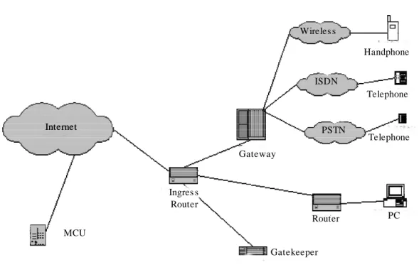
Figure 2.1 depicts the infrastructure of a VoIP system. A significant component of the model is the Gateway. The Gateway is in charge of converting the media provided in one type of network to the format required for another type of network.
Figure 2.1 VoIP Infrastructure
The voice packets are transported using IP in compliance with a specification for transmitting multimedia (voice, fax, video, and data) across a network. There are several specifications, recommendations, and standards for performing this transmission:
ITU−T H.323
Media Gateway Control Protocol (MGCP), from level 3, Bellcore, Cisco, and Nortel
IETF MEGACO/H.GCP
IETF Session Initiation Protocol (SIP) ITU−T T.38
IETF SIGTRAN
Skinny, from Cisco
SIP is nowadays of special interest. SIP is an IETF standard specified in Request For Comments (RFC) 3261[3], and defines a signaling protocol for creating, modifying, and terminating sessions1. Regarding
the data transport itself, the most important protocol to handle this is the Real−Time Protocol (RTP)[2]. As far as the quality of service (QoS) and performance are concerned, VoIP is a delay−sensitive application, so a well−engineered, end−to−end network is necessary. Issues such as delay, jitter, congestion, packet−loss, and misordered packet arrival must be carefully handled.
1. These sessions are considered exchanges of data between participants, and include Internet telephone calls, multimedia Internet Wireles s ISDN PSTN Internet Ingres s Router MCU Gateway Gatekeeper Router PC Telephone Telephone Handphone
The following list summarizes some examples of services provided by a VoIP network according to market requirements:
Phone−to−phone
PC−to−phone and phone−to−PC fax−to−fax
fax−to−email and email−to−fax Wireless Connectivity
PC−to−PC
This study is concerned with the PC−to−PC VoIP service, assuming the users have the appropriate software and hardware installed on their PCs (user agents, sound card, headsets, etc.).
3 Introduction to SIP and RTP
This section provides a short introduction to the Session Initiation Protocol (SIP) and the Real−Time Protocol (RTP), widely used in VoIP technology. SIP is the most commonly used protocol to create and manage the VoIP media sessions, while RTP is the transport protocol in charge of the transmission of the data in a VoIP session.
3.1 Session Initiation Protocol (SIP)
3.1.1 Introduction
SIP is a signaling protocol used for establishing, modifying, and terminating sessions between users. SIP is defined by IETF as a standard in RFC 3261.
There are many applications of the Internet that require the creation and management of sessions, such as multimedia real−time exchanges, which this project is concerned with. There are various protocols designed to carry this real−time data (voice, video, etc.), such as Real−Time Protocol (RTP), and SIP works in concert with these protocols by establishing, managing, and terminating these exchanges.
As described in the SIP standard (RFC 3261), SIP is an application−layer control protocol with the ability to manage multimedia sessions, such as Internet telephone calls, which makes this protocol suitable for its use in VoIP.
SIP supports five aspects regarding the establishment and termination of communications sessions:
User location: Determination of the destination end system.
User availability: Determination of the willingness of the call party to accept a call to
this device.
User capabilities: Negotiation of the session parameters.
Session setup: Establishment of the session.
Session management: Modification and termination of the session.
Finally, two important ideas to keep in mind are that SIP does not provide services, but rather provides primitives that can be used to implement these services; and that SIP works with either IPv4 or IPv6.
SIP makes use of an offerer/answerer model, in which the caller represents the offerer and the called party represents the answerer.
The purpose of this section is to introduce the SIP protocol. Details such as security issues related to SIP (one of the goals of this project) are described in detail later in this document.
3.1.2 Functionality
This subsection presents a simple example of the use of SIP between two end users. This example is related to the SIP Trapezoid and it only shows a simple SIP message exchange. The SIP Trapezoid is depicted in figure 9.1 and described in section 9.1.
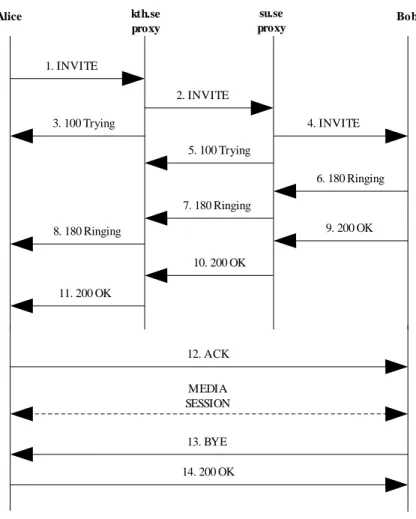
In this example, one user (the offerer, referred to as "Alice" for simplicity) calls another user (the answerer, referred to as "Bob") using his SIP identity, a type of Uniform Resource Identifier (URI), called SIP URI. This SIP URI is similar to an email address and it contains the user name and the host identifier (for example alice@kth.se). Alice sends a request called INVITE2to Bob’s provider
SIP server (su.se proxy) via her provider’s SIP server (kth.se proxy). If Bob accepts the call, the media session is established. Figure 3.1 depicts this process. Section 3.1.3 briefly describes the requests and responses.
Figure 3.1 SIP setup
There are other aspects of SIP functionality besides the establishment and the termination of the call. For instance another important issue regarding SIP is the registration of the users with their provider’s servers. When a SIP−based device (called User Agent) comes online, it first must perform registration with a SIP Registration Server (called Registrar). This process is handled by sending a REGISTER message. Registrations are not normally permanent, they bind the user’s ID with an IP address where it can be contacted. A brief description of the REGISTER message is given in the next subsection.
The following list enumerates the main abilities SIP has in the VoIP context:
2. INVITE is an example of SIP method. These methods are described in section 3.1.3.
Alice kth.se proxy su.se proxy Bob 1. INVITE 2. INVITE 4. INVITE 3. 100 Trying 5. 100 Trying 6. 180 Ringing 7. 180 Ringing 8. 180 Ringing 9. 200 OK 10. 200 OK 11. 200 OK 12. ACK MEDIA SESSION 14. 200 OK 13. BYE
Registering a user with a system Inviting users to join a session
Negotiating the terms and conditions of a session
Establishing the media stream between two or more end points Terminating sessions
More information and details about SIP can be found in the SIP standard (RFC3261).
3.1.3 SIP Requests and Responses
As seen in Figure 3.1, SIP is based on HTTP−like request/response (also referred to as offer/answer) model. The SIP specification defines a set of request messages (which in turn invoke SIP methods) and responses to those requests.
The most important method in SIP is the INVITE method, which is used to establish a session between participants (these participants are supposed to have previously registered with their respective provider’s SIP Registrars). As an example, the following paragraph shows how the first INVITE message shown in Figure 3.1 looks:
INVITE sip:bob@su.se SIP/2.0
Via: SIP/2.0/UDP pc33.kth.se;branch=z9hG4bK776asdhds Max−Forwards: 70
To: Bob <sip:bob@su.se>
From: Alice <sip:alice@kth.se>;tag=1928301774 Call−ID: a84b4c76e66710@pc33.kth.se
CSeq: 314159 INVITE
Contact: <sip:alice@pc33.kth.se> Content−Type: application/sdp Content−Length: 142
(Alice’s SDP not shown)
The first line identifies the method name, and the following lines are a minimum required set of fields of the INVITE message header. These fields are briefly described below:
Via contains the address at which Alice expects to receive response to her request. The
branch parameter identifies the transaction.
To contains a display name and the SIP URI to which the request was directed.
From identifies the originator of the request by his/her display name and his/her SIP
URI. The tag parameter is used for identification purposes.
Call−ID is a globally unique identifier for this call.
CSeq stands for Command Sequence and it is an integer used as a traditional sequence
number.
Contact is a SIP URI that represents a direct route to contact Alice.
Max−Forwards limits the number of hops to the destination.
Content−Length defines the length of the message body.
Section 20 in SIP standard describes the complete set of header fields.
The details of the session to be established are not explicitly described by SIP, but these details are carried in the SIP message body encoded by other protocol, typically the Session Description Protocol (SDP)[8].
Another important SIP method is REGISTER. As said above, this method is used to register a device address with a system (via SIP Registration Server or Registrar). It is necessary for a device to perform the registration in order to provide location information to permit incoming calls.
Other SIP methods are:
ACK: Confirms that the client has received a final response to an INVITE request.
BYE: Indicates that the user wants to terminates a session. This message may be sent by
either the originator of the call or the receiver.
CANCEL: Cancels a previous request message3.
There are many different responses to these methods carried by request messages, all of them divided into six different groups [7]:
1xx Responses: Informational Responses (e.g. 180 Ringing and 100 Trying).
2xx Responses: Successful Responses (e.g. 200 OK).
3xx Responses: Redirection Responses (e.g. 302 Moved Temporarily).
4xx Responses: Request Failure Responses (e.g. 404 Not Found).
5xx Responses: Server Failure Responses (e.g. 503 Service Unavailable).
6xx Responses: Global Failure Responses (e.g. 600 Busy Everywhere).
The complete list and description of the SIP requests and responses can be found in the SIP standard.
3.2 Real−Time Protocol (RTP)
3.2.1 Introduction
Since 1996, the Real−Time Protocol (RTP) is an IETF standard specified in Request For Comments (RFC) 1889. RTP is a transport protocol for real−time applications which provides end− to−end network functions and services suitable for transmitting real−time data, such as audio, video, or simulation data, over unicast or multicast network services. RTP runs on top of a non− reliable transport protocol, such as UDP, to make use of the underlying multiplexing and checksum services.
RTP also provides a control protocol called RTP Control Protocol (RTCP), used for monitoring data delivery and to provide minimal control and identification functionality.
The services provided by RTP for the real−time data delivery include sequence numbering, payload type identification (such as audio samples or compressed video data), timestamping, and delivery monitoring. Security services for RTP and RTCP may be provided in several different ways, such as IPSec encapsulation over Virtual Private Networks (VPNs). The RTP standard also presents
some mechanisms to provide this security. However, a powerful alternative is the RTP profile Secure Real−Time Protocol (SRTP)[15]. RTP security issues and solutions to secure the RTP and RTCP traffic (one of the goals of this project) are described in detail later in this document.
3.2.2 Terminology and definitions
Of special interest for us is the definition of an RTP Session given in RFC 1889:
"RTP session: The association among a set of participants communicating with RTP. For each participant, the session is defined by a particular pair of destination transport addresses (one network address plus a port pair for RTP and RTCP). The destination transport address pair may be common for all participants, as in the case of IP multicast, or may be different for each, as in the case of individual unicast network addresses plus a common port pair. In a multimedia session, each medium is carried in a separate RTP session with its own RTCP packets. The multiple RTP sessions are distinguished by different port number pairs and/or different multicast addresses"[2].
Other significant definitions are summarized as follows:
Synchronization Source (SSRC): The source of a stream of RTP packets identified by a
32−bit numeric SSRC identifier carried in the RTP header, so as not to be dependent upon the network address. The RTP sender is an example of such a source. More information can be found in [2].
Contributing Source (CSRC): A source of a stream of RTP packets that has contributed
to the combined stream produced by the RTP mixer. The list of these sources is called CSRC list . More information about RTP mixer can be found in [2].
End system: An application that generates the content to be sent in RTP packets and/or
consumes the content of received RTP packets. An end system can act as one or more synchronization sources in a particular RTP session, but typically act as only one (See [2]).
3.2.3 RTP Packet Format
The RTP packet consists of a fixed header, a possibly empty list of contributing sources (unicast transmission), and a payload. The payload contains the real−time application data, such as audio or video data. Detailed information about the payload types is given in the RTP standard (RFC 1889). The RTP header is depicted in Figure 3.2, and the fixed part has the following fields:
Version (V): 2 bits. This field identifies the version of RTP. By default it is set to the
value 2 for the RFC 1889 RTP specification.
Padding (P): 1 bit. Set to the value 1 if padding has been applied to this packet.
Extension (X): 1 bit. If the extension bit is set, the header is followed by exactly one
extension field. Detailed information about the RTP extensions is given in section 5.3.1 in [2].
CSRC count (CC): 4 bits. This field contains the number of CSRC identifiers that follow
Marker (M): 1 bit. The interpretation of this field is defined by a RTP profile. See
section 5.3 in [2] for further information about RTP profiles.
Payload Type (PT): 7 bits. This field identifies the format of the RTP payload and
determines its interpretation by the real−time application.
Sequence Number: 16 bits. This field increments by one for each RTP packet sent. It
may be used by the receiver to detect packet loss. The initial value of this field is random.
Timestamp: 32 bits. This value reflects the sampling instant of the first octet in the RTP
packet. As for the sequence number, the initial value is random.
SSRC: 32 bits. This field identifies the synchronization source.
The CSRC list (zero to fifteen items, each 32 bits in length) identifies all the contributing sources for the payload of the packet. As noted above, the CC field in the fixed header contains the number of sources identified.
0 8 16 31
V P X CC M PT Sequence Number
Timestamp
Synchronization Source (SSRC) Identifier Contributing Source (CSRC) Identifier
...
Figure 3.2 RTP Header Format
In the figure, the dark grey part corresponds to the fixed header, while the light grey part indicates the optional CSRC list.
3.2.4 RTCP Packet Format
RTP specification in defines several types of RTCP packets:
SR: Sender Report. Used by a sender for transmitting statistics.
RR: Receiver Report. Used by a receiver for transmitting statistics.
SDES: Source Description items.
BYE: Indicates end of participation.
APP: Application specific functions.
Each RTCP packet begins with a fixed part similar to that of RTP data packets. This part is followed by structured elements of variable length according to the packet type, but always ending on a 32−bit boundary[2].
0 8 16 31
V P RC PT=SR=200 Length
SSRC of sender
NTP timestamp, most significant word NTP timestamp, least significant word
RTP timestamp Sender’s packet count
Sender’s octet count SSRC_1 (SSRC of first source)
Fraction lost Cumulative number of packets lost Extended highest sequence number received
Interarrival jitter Last SR (LSR) Delay since last SR (DLSR) SSRC_2 (SSRC of second source)
...
Profile−specific extensions
Figure 3.3 SR RTCP Packet Format
The dark gray part at the top of the figure identifies the RTCP header. This is followed by the sender info. The white part corresponds to the different report blocks. Finally certain extensions (depending on the RTP profile being used) may be added.
The RTCP header contains the following fields:
Version (V): Identical to that in RTP.
Padding (P): Used for the same purpose as in the RTP header.
Reception Report Count (RC): 5 bits. Indicates the number of reports in this packet.
Packet Type (PT): 8 bits. In this case it is set to the value 200, identifying a SR packet.
Length: 16 bits. Length of the RTCP packet in 32−bit words minus 1.
SSRC: 32 bits. The SSRC identifier for the RTCP packet originator.
The description of the rest of the fields is out of the scope of this document. For further information about the sender info, the report blocks, and the extensions, refer to RTP standard (RFC 1889).
4 Security Services
A Security Service is a service that enhances the security of the systems and the transfers between them, and is intended to counter Security Attacks4. The Security Services make use of Security Mechanisms. As a matter of fact, a Security Service implements a Security Policy, and is implemented by a Security Mechanism. We define Security Mechanism as a mechanism which is designed to detect, prevent and/or recover from a Security Attack. In the first section, a brief description of Security Attacks is given. The rest of the sections deal with each one of the main six5 Security Services: Authentication, Access Control, Confidentiality, Integrity, Non−Repudiation, and Availability. For further information, see [41].
4.1 Security Attacks
Security Attacks are divided into two main groups: Passive Attacks and Active Attacks. A short description is given in the following paragraphs.
Passive Attacks: Those whose goal is to obtain information that is being transmitted. Passive
Attacks are divided into two main groups:
Release of message contents: Interception of the content (possibly sensitive) of a message.
Traffic Analysis: Interception for observing the patterns of the messages to guess the nature of a communication.
Active Attacks: Those which involve some modification or alteration of the data stream, or the
creation of a false stream. Active Attacks are in turn divided into four groups: Masquerade: It implies one entity pretending to be a different entity.
Replay Attack: It consists of the capture of sensitive data, and its subsequent retransmission to produce an unauthorized effect.
Modification of messages: It implies the alteration, deletion, delay, or reordering of some portion of a message, producing an unauthorized effect.
Denial of Service (DoS) Attack: DoS attack prevents or inhibits the normal use or management of communication facilities by disabling or overloading them.
Passive Attacks are difficult to detect, since they do not imply alteration of the data. Thus, the solution is the prevention of these attacks, and the mechanism used is encryption.
On the other hand, Active Attacks are difficult to prevent, since that would imply the physical protection of resources and paths. Therefore, the solution is to detect and recover from these attacks.
4. A security attack is defined as an assault on system security that derives from an intelligent threat (which might exploit a vulnerability), and compromises the security of information owned by a organization.
5. In fact, OSI establishes five main Security Services, but I have added here a short definition for a sixth: Availability, since it is very related to Denial of Service (DoS) attacks, unfortunately very common nowadays.
4.2 Authentication
Authentication is the assurance that the communicating entity is who it claims to be. Two main concepts regarding Authentication are involved in an ongoing interaction:
At the connection initiation the service assures that both entities are authentic.
The service must assure that the connection is not interfered with in such a way that a third party can masquerade as one of the two legitimate parties for unauthorized purposes.
We must distinguish between two specific authentication services:
Peer Entity Authentication: This services implies the corroboration of the identity of a peer
entity, and attempts to provide confidence that an entity is not performing either a masquerade or unauthorized replay of previous connections.
Data Origin Authentication: Provides for the corroboration of the source of a data unit. This
specific authentication services assures, in a connectionless transfer, that the source of a received message is as claimed. Note that this specific service does not protect against duplication or modification of data units.
4.3 Access Control
Access Control service deals with the ability to limit and control the access to host systems and applications via communication links6. A more general definition refers to the prevention of
unauthorized use of computer and network resources.
Note that it requires previous authentication to assign the correct right to each user to achieve an access control service.
4.4 Data Confidentiality
Data Confidentiality service is defined as the protection of transmitted data from passive attacks, or more generally, the protection of data from unauthorized disclosure.
Regarding the content of the data transmission, it is possible to apply Confidentiality at several levels, such as the all messages level, some messages level, some fields of the messages level, etc. Note that such refinements might be, in certain situations, less useful and even more complex to implement. Another important aspect in Data Confidentiality is the Flow characteristics Privacy, which deals with the prevention against traffic analysis attacks mentioned in section 4.1.
The following list enumerates the different specific confidentiality services: Connection Confidentiality (connection protection)
Connectionless Confidentiality (single data block protection)
Selected−Field Confidentiality (on a connection or of a single data block)
4.5 Data Integrity
The Data Integrity service assures that the data received are exactly as sent by an authorized entity (i.e. no alteration, modification, insertion deletion, or replay). The integrity service, as in the confidentiality service, can be applied to a connection, single message, or selected fields of a single message.
It is necessary to distinguish between integrity services with or without recovery. This means that we would like just to report an integrity violation (service without recovery), or to report and recover from the violation (service with recovery).
The following list shows the different specific integrity services: Connection Integrity with Recovery
Connection Integrity without Recovery Selected−Field Connection Integrity Connectionless Integrity
Selected−Field Connectionless Integrity
4.6 Non−Repudiation
The Non−Repudiation service prevents the sender or the receiver from denying that they transmitted a message. Therefore, when a message is sent, the receiver can prove that the alleged sender sent the message. Similarly, when a message is received, the sender can prove that the receiver in fact received the message.
Thus, we distinguish between two different specific Non−Repudiation services: Origin Non−Repudiation
Destination Non−Repudiation
4.7 Availability
As described in [41], Availability is "the property of a system or a system resource being accessible and usable upon demand by an authorized system entity, according to performance specifications for the system". Thus, an Availability service protects a system so as to ensure its availability. One the main purposes of an Availability service is the protection against DoS attacks, described in section 4.1.
5 Cryptography Overview
This chapter is divided into two main parts and gives a brief introduction to the basic elements and methods used by cryptography. First, some basic knowledge necessary to understand concepts as Private or Public Cryptography is given. The same subsection also presents some other concepts, such as certificates and the one−way functions. The second part is specifically oriented to this project and the cryptographic tools it utilizes (such as the algorithms used by SRTP). This part deals with some specific cryptographic algorithms and mechanisms to provide confidentiality and message integrity: Advanced Encryption Standard (AES)[34] and HMAC−SHA1[35] are described in detail here. Most of the information in this section has been obtained from [41], along with other sources.
5.1 Basic Knowledge
5.1.1 Introduction
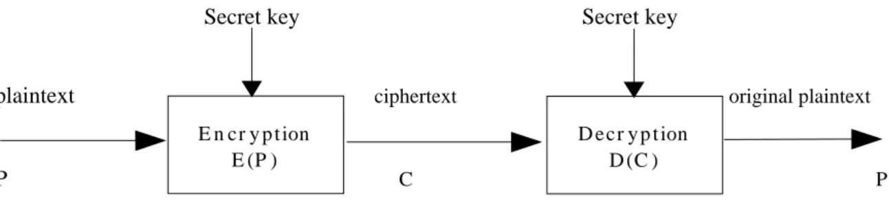
Cryptography is the science of secret writing. We can also define it as the art of keeping messages private over an insecure medium. The generic scenario is shown in Figure 5.1, obtained from [41]. This scenario deals with two entities who want to communicate in a secure way, adding privacy to the message exchange, so that an intruder (eavesdropper) has no possibility to read the messages. The solution to this issue consists of coding such messages in order to avoid an unauthorized person retrieving the original text. This scheme is called symmetric cryptography, and it is the most simple case in cryptography. Another possible cryptographic scheme is the asymmetric cryptography. Further sections will give a short description of both cryptographic mechanisms.
Secret key
Secret key
plaintext
ciphertext original plaintext
P
C P
Figure 5.1 Simplified Model of Symmetric Encryption
We have 5 components in this scheme:
Plaintext: This is the original message or data that is fed into the algorithms as input.
Encryption algorithm: The encryption algorithm performs various substitutions and/or
transformations on the plaintext. It is also called cipher.
Secret key: The secret key is also input to the algorithm. The exact substitutions and/or
transformations performed by the algorithm depend on this key. E n cr y p t ion
E (P )
D ecr y p t ion D (C )
Ciphertext: This is the scrambled message produced as output. It depends on the
plaintext and the secret key. Note that two different keys applied on the same plaintext, and using the same algorithm, will produce two different ciphertexts.
Decryption algorithm: This is essentially the encryption algorithm run in reverse. It
basically takes the ciphertext and the same secret key and produces the original message. The following paragraphs deal with some terms and their definitions.
As said above, a cipher is a mathematical function used to encrypt/decrypt messages. It is also called cryptographic algorithm.
The process of coding a message is called encryption E(P), and its output is the ciphertext. Decryption D(C) is recovering the original message. Thus, we have that E(P)=C and D(C)=P, such that D(E(P))=P.
Cryptanalysis is the science of breaking ciphers. It consists of the process of attempting to discover the original message (plaintext) or the key.
Cryptology encompasses both cryptography and cryptanalysis subjects.
It is important to remark that, in most cases, the security of encryption relies on the secrecy of the key, rather than the secrecy of the cipher. By using cryptography we are mainly providing confidentiality using keys, although other security mechanisms supporting the rest of security services (such as the digital signature for data origin authentication) make use of cryptography. Thus, cryptography enhances computer security, but it is not a substitute for it.
5.1.2 Symmetric Cryptography
Symmetric encryption is also referred to as conventional encryption, secret−key, or single−key encryption. It remains the most widely used of the two types of encryption.
In this scheme, one only key is used by the entities to encrypt and decrypt a message, so that this shared key, which must be kept secret by both entities, is previously exchanged, or even distributed by a trusted third party to both entities. The basic scenario and its components were shown in the previous section, in the Figure 5.1.
The two main requirements for secure use of symmetric encryption are the following:
A strong encryption algorithm is needed. We would like the algorithm to be such that an intruder with access to this algorithm and some different ciphertexts, would be unable to decrypt those ciphertexts and/or guess the secret key used. This requirement becomes stronger if we consider that the intruder should not be able to figure out the key even when having access to the ciphertext and the matching plaintext.
Both sender and receiver must have obtained copies of the secret key in a secure and secret fashion, and must keep it secret. Of course, if someone intercepts the key and knows the algorithm being used, the exchanged data is readable.
Thus, this key exchange is one of the main challenges in symmetric cryptography, and the fact of distributing or exchanging this key in a secret and secure way becomes a problem in this scheme7. In
addition to this, if the number of users in a certain community is high, so it is the number of keys. This may cause an important overload to the administration system.
We have to distinguish between two different types of symmetric ciphers:
Stream ciphers: take a data stream and a key as input, and combine each bit of plaintext with one bit of the key. These ciphers are suitable for hardware implementation.
Block ciphers: operate on data blocks of a particular size and encrypt them with a key, and are suitable for software implementations.
Some examples of symmetric ciphers are Data Encryption Standard (DES)[49], Triple DES (3DES), International Data Encryption Algorithm (IDEA), Blowfish, RC5, and Advanced Encryption Standard (AES). The latter is also known as Rijndael Cipher, and it is the algorithm selected in the SRTP implementation, provided in this document, to encrypt the media stream. A wide description of AES cipher is given in section 5.2.1, and a shorter description of DES and 3DES is also given in section 5.2.2.
5.1.3 Asymmetric Cryptography
Asymmetric encryption is also known as public−key encryption. It is of equal importance to symmetric encryption, and it finds use in message authentication and key distribution.
Public−key cryptography was firstly publicly proposed by Diffie and Hellman in 1976, and it involves the use of two different keys, the private and the public key. This fact has important consequences in the areas of confidentiality, key distribution and authentication.
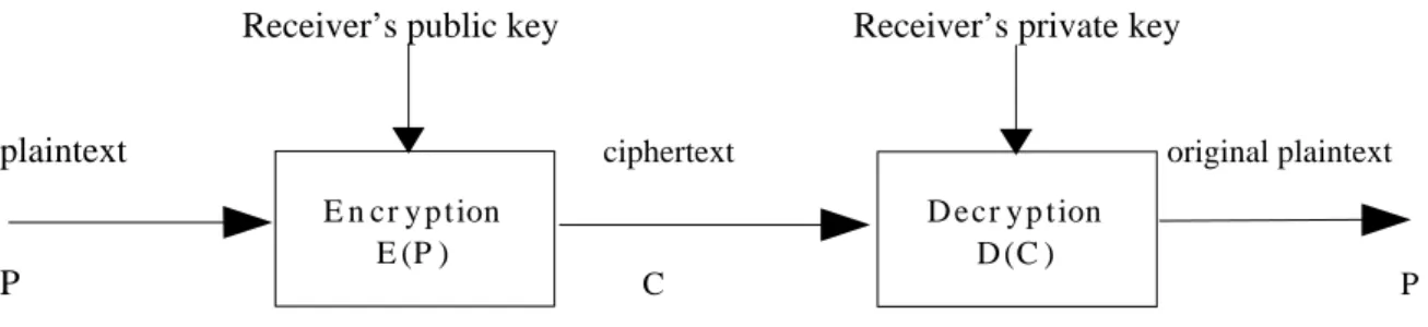
Asymmetric cryptography has the same components as the symmetric cryptography, except the secret key. Instead of using the same secret key to encrypt and decrypt the message, public−key cryptography makes use of two different keys, grouped in a owner’s pair. One of the keys of this pair is used for encryption, and the other is used for decryption. These keys are called the private key and the public key. The former is kept secret by the owner and it is used to encrypt data, as well as decrypt data encrypted by the public key of the pair. On the other hand, the public key is made public by the owner for others to use, and it is used to encrypt data, or to decrypt data encrypted with the private key. With this approach, all participants in a encrypted communication have access to other participant’s public keys. Furthermore, as said before, private keys are generated locally by each participant and therefore never distributed.
The essential steps in public−key cryptography, shown in Figure 5.2, are the following: Each user generates his or her pair of keys.
Each user places one of the two keys in an accessible public register. The companion key is kept secret by its owner.
One user who wants to send a private message to the other, encrypts that message with the receiver’s public key.
The receiver gets the message and decrypts it with his or her private key. Note that only the receiver can decrypt the message, since it is assumed that he or she is the only who knowing the private key.
Receiver’s public key Receiver’s privatekey
plaintext
ciphertext original plaintext
P
C P
Figure 5.2 Simplified Model of Asymmetric Encryption providing Confidentiality
Another possibility in asymmetric encryption is its use as the basis for digital signatures. Let us consider the case in which one user sends a message encrypted with his or her private key. In this scheme, data origin authentication (without confidentiality) is provided, since the sender proves his or her identity by being the only possessor of the right private key.
The most important examples of public−key algorithms are RSA Public−Key Encryption Algorithm, and the Diffie−Hellman Key Exchange. Other public−key ciphers are Digital Signature Standard (DSS) and Elliptic−Curve Cryptography.
5.1.4 Symmetric Cryptography vs. Asymmetric Cryptography
Public−key cryptography is powerful, but it does not suit every situation. Furthermore, there are some common misconceptions concerning public−key cryptography (from [41]):
Public−key encryption is more secure from cryptanalysis than secret−key cryptography. As
a matter of fact, the security in any cryptography scheme depends on the length of the key and the computational work needed to break the cipher. In principle, there is no proof about the idea that one scheme is superior to the other from the point of view of withstanding cryptanalysis.
Public−key encryption has made secret−key encryption obsolete. On the contrary, the
computational overhead of current public−key cryptography makes secret−key cryptography will not be abandoned.
Key distribution in public−key cryptography is trivial. In fact, it is still necessary for public−
key cryptography to use some form of protocol, often involving a central and trusted agent. Furthermore, "the procedures involved are not simpler or more efficient than those used for secret−key cryptography" [41].
Thus, asymmetric algorithms are not substitute for symmetric algorithms. The most common solution, adopted in most of the models, consists of a hybrid cryptosystem.
5.1.5 Cryptanalysis
As said above, cryptanalysis is the process of attempting to discover the plaintext or the key. The attacker will act depending on the information available and the nature of the encryption scheme.
E n cr y p t ion E (P )
D ecr y p t ion D (C )
A encryption algorithm is generally designed to withstand a known−plaintext attack. In this attack, the information available for the cryptanalyst is the following:
Encryption algorithm Ciphertext to be decoded
One or more plaintext−ciphertext matching pairs formed with the secret key
If an encryption algorithm is to be proved as secure (computationally secure), the applied criteria comprises these two aspects (from [41]):
The cost of breaking the cipher exceeds the value of the encrypted information The time required to break the cipher exceeds the useful time of the information
Table 5.1 (from [41]) shows how much time is involved in the key search for various key sizes.
Key Size (bits)
Key Size (bits) Number of AlternativeNumber of Alternative Keys Keys Time Required at 1 Time Required at 1 Encryption/µs Encryption/µs Time Required at 10 Time Required at 1066 Encryption Encryption/µs/µs 32 232 = 4.3 x 10⁹ 231 µs = 35.8 minutes 2.15 milliseconds 56 256 = 7.2 x 10¹⁶ 255 µs = 1142 years 10.01 hours 128 2128 = 3.4 x 1038 2127 µs = 5.4 x 1024 years 5.4 x 10¹⁸ years 168 2168 = 3.7 x 1050 2167 µs = 5.9 x 1036 years 5.9 x 1030 years 26 characters (permutation) 26! = 4 x 1026 2 x 1036 µs = 6.4 x 10¹² years 6.4 x 10⁶ years
Table 5.1 Average Time Required for Exhaustive Key Search[41]
5.1.6 One−way Hash Functions and MACs
A one−way hash function accepts a variable size message M as input and returns a fixed−size message digest H(M). It is used to authenticate a message so that the hash result is sent along with the original message in such a way that the recipient can verify that the message digest is authentic. The function H() is called one−way function since it is relatively easy to compute (one way), but significantly harder to reverse. Some examples of one−way hash functions are MD5 Message Digest Algorithm and Secure Hash Algorithm (SHA−1). A detailed description of the latter is given in section 5.2.3, since it is used in the SRTP implementation.
One−way hash functions are also known as non−keyed hash functions or Message Description Code (MDC).
Some requirements for secure hash functions are described in [41] as follows: H() can be applied to a block of data of any size
H() produces a fixed−length output
H(x) is relatively easy to compute for any given x
One−way property: Given a value h, it is computationally infeasible to find x such that H(x) = h Weak collision resistance property: Given a block x, it is computationally infeasible to find y≠x
Strong collision resistance property: It is computationally infeasible to find a pair (x, y) such that H(y) = H(x)
On the other hand, when a shared secret is added to compute the digest, we get a Message Authentication Code (MAC). Thus, we can illustrate the MAC as follows:
MACM = F(KAB, M) where KAB is the secret shared between the parties.
MACs are also referred to as keyed hash functions.
With this approach, message integrity and data origin authentication are provided. Several algorithms can be used to generate the digest, such as DES, although in recent years, there has been increased interest in developing a MAC based on a cryptographic hash code (Hash−Based MAC, HMAC). The reasons and approaches to this technique are described in the next section.
5.1.7 Overview of the Hash−based Message Authentication Code : HMAC The reasons for the interest in basing MAC on hash functions are the following:
Cryptographic hash functions execute faster in software than the conventional encryption algorithms such as DES.
Library code for cryptographic hash functions is widely available.
Unlike conventional encryption algorithms, there are no export restrictions for cryptographic hash functions.
The approach which has received more support is HMAC, which treats the cryptographic hash function as a black box8, enhancing efficiently the use of different functions to generate the digest. A wide description of HMAC is given in section 5.2.4, since it is used (based on SHA−1 hash algorithm) for the SRTP implementation, as well as for other important protocols such as TLS and IPSec.
5.1.8 Certificates
Public−key cryptography is related to the use of certificates. The most widely used type of certificate is defined in ITU−T X.509 standard (see [19]). The heart of the X.509 scheme is the public−key certificate associated with each user.
Certificates are assumed to be created and signed by a trusted third party, known as the issuer or Certification Authority (CA). Basically, a certificate contains the public key associated with each user, among other information, such as the user name and the certificate expiration date.
A wide description of certificates and certification infrastructures (also referred to as Public−Key Infrastructures) is given in section 6.
8. The hash function implementations can be integrated as modules when implementing HMAC, making those functions easy to modify or even replace if desired.
5.1.9 Location of encryption devices
Before using encryption mechanisms, it is necessary to decide what and where we want to encrypt. There are two fundamental alternatives:
Link encryption End−to−end encryption
Link encryption refers to lower layers (physical or link layer) encryption. It is the easiest way to encrypt data, and it is often implemented by hardware encryption devices in every node in the network. Every node traversed decrypts the incoming packet, process it, and encrypts it again before sending it out the link. The problem in Link encryption is that the data is in clear text inside each node it has to traverse to reach its destination.
The alternative to Link encryption is End−to−end encryption. It places the cryptographic equipment between the network and the transport layers, thus protecting the data from the source to the final destination. Disadvantages of this scheme are that it allows traffic analysis, and makes the key management more complex.
The encryption can also take place at the highest OSI layers (presentation and application), making it independent of the network used, but requiring interaction with the user’s software.
5.2 Basic Algorithms and Methods
5.2.1 Advanced Encryption Standard (AES)
5.2.1.1 AES History
In 1997, the National Institute of Standards and Technology (NIST) issued a call for proposals for a new Advanced Encryption Standard (AES), which should have a security strength equal to or better than other algorithms such as 3DES, and provide significantly improved efficiency. In addition to these requirements, NIST specified that AES must be a symmetric block cipher with a block length of 128 bits and support for key lengths of 128, 192 and 256 bits.
The selected final standard adopted the Rijndael cipher as the proposed AES algorithm. Rijndael was developed by Dr. Joan Daemen and Dr. Vincent Rijmen, and was published as a final standard (FIPS PUB 197) in November of 2001.
5.2.1.2 Overview of the Algorithm
AES uses a block length of 128 bits and a key length which can be of 128, 192, or 256 bits, although in the description in this section we assume a length of 128 bits for the key. This 128−bit length is likely to be the most commonly implemented and the one used in the SRTP implementation described in section 13.2. The mode of operation of AES used in such an implementation is Counter Mode (CTR)[47].
When it comes to computational efficiency, Rijndael cipher is a low−cost, high−speed encryption algorithm. This is the main reason which makes Rijndael cipher suitable for real−time traffic
encryption, where the performance of the encryption/decryption process becomes very important. Figure 5.3 (from [48]9) shows the time taken for the different tasks to perform by some of the AES
candidates, included Rijndael.
Figure 5.3 Time (clock cycles) taken by some AES candidates [48]
The overall encryption/decryption structure in CTR mode is shown in Figure 5.4, based on figure 1 in [47]. In this figure, M is the plaintext, K is the key, and ctr is a counter. The ciphertext is (ctr, C), or, more generally, C together with something adequate to recover ctr. Decryption is the same as encryption with the M and the C interchanged10. C is the XOR (exclusive−or) of M and the first |M|
bits of the pad EK(ctr) | EK(ctr+1) | EK(ctr+2)... .
9. This figure appears in this document with the explicit permission of its owner, Professor Jean−Jacques Quisquater, Microelectronics Laboratory Crypto Group, Université Catholique de Louvain (UCL), Louvain, Belgium.
Figure 5.4 Encryption and Decryption Process in CTR Mode[47]
The structure of the algorithm is quite simple. For both encryption and decryption, the cipher starts by an Add Round Key stage, followed by nine rounds of four stages each one. These stages are the following:
Substitution of bytes (Byte Sub) Shifting of rows (Shift Row) Mixing of columns (Mix Column) Add Round Key
Finally, there is a final round of three stages (all the stages indicated above, except the mixing of the columns). Figure 5.5 (based on figure 2 from [46]) depicts the structure of a full encryption round.
Figure 5.5 AES Encryption Round [46]
E
C tr K M1 C1E
ctr +1 K M2 C2E
ctr + n −2 K Mn − 1 C1E
ctr + n −1 K Mn C2 Encryption Proces sE
C tr K C1 M1E
C tr + 1 K C2 M2E
ctr + n −2 K Cn − 1 M1E
ctr + n −1 K Cn M2 Decryption Proces s5.2.2 Data Encryption Standard (DES)
DES is the most widely used encryption algorithm. It was adopted by the NIST in 1977 (FIPS PUB 46). It is also known as the Data Encryption Algorithm (DEA) by ANSI and as the DEA−1 by the ISO. The length of the plaintext block to be processed is 64 bits, and the length of the key is 56 bits. The structure of the algorithm is a minor variation of the Feistel Structure (see [41], pages 32−34). There are sixteen rounds of processing, each one using a subkey generated from the 56−bit original. More details concerning the encryption/decryption process are in [49].
Nowadays, DES is a worldwide standard, and its security has been long questioned, since several studies have estimated costs and times for attacking and breaking DES. Despite numerous approaches no one has thus far succeeded in discovering a fatal weakness in the algorithm. However, a more serious concern is the key length. In July 1998 the Electronic Frontier Foundation (EFF) announced that it had broken a DES encryption, in less than three days, using a cracker machine built for less than $250,000. Assuming the EFF machine performs 106decryptions/µs, the use of a key of 128 bits,
very common among contemporary algorithms, it would take the EFF cracker over 1018years to break
the code. So a 128−bit key is guaranteed to result in an algorithm that is unbreakable by brute force with present technology.
In 1999, 3DES was incorporated as part of the Data Encryption Standard. 3DES uses three keys and three executions of the DES algorithm, so that the effective length of the key becomes 168 bits, making the brute−force attacks effectively impossible. Although 3DES is nowadays widely used, AES is intended to replace it in a number of years. Meanwhile, 3DES and AES will coexist as FIPS− approved algorithms, allowing for a gradual transition to AES.
5.2.3 Secure Hash Algorithm (SHA)
5.2.3.1 SHA History
The Secure Hash Algorithm (SHA) was also developed by the NIST, and was published as a standard (FIPS PUB 180) in 1993. A revised version was issued as FIPS PUB 180−1 in 1995, and is generally known as SHA−1.
5.2.3.2 Overview of the Algorithm
As described in [41], the algorithm takes a message with a maximum length of 264bits as input, and
generates a digest of 160 bits. The input is processed in 512−bit blocks.
The overall process performed by the algorithm to produce a message digest is depicted in the figure 5.6 (based on figure 3.4 from [41]).
Figure 5.6 Message Digest Generation Using SHA−1[41]
The processing consists of four steps, briefly described as follows:
Step 1: Append padding bits. The message must be padded so that its size is congruent to
448 modulo 512. Note that padding is always added, even if the message has already the desired length.
Step 2: Append length. The length of the original message, in a block of 64 bits, is
appended to the message.
Step 3: Initialization of the MD buffer. This 160−bit length buffer is used to hold
intermediate and final results of the hash function. This buffer appears as five 32−bit registers, each one initialized with certain hexadecimal values.
Step 4: Process message in 512−bit blocks. This is performed by a module, known as
compression function, which consists of four rounds of 20 stages each. Each round uses a different primitive logical function. This step is depicted in Figure 5.7 (based on figure 3.5 from [41]).
Figure 5.7 SHA−1 Processing of a Single 512−Bit Block (SHA−1 Compression Function)[41]
5.2.4 Hash−Based Message Authentication Code (HMAC)
The design objectives for HMAC are described in [35] and [41] as follows:
To use, without modifications, available hash functions that perform well in software and for which code is freely and widely available.
To allow for easy replaceability of the embedded hash function in case faster or more secure hash functions are found or required.
To preserve the original performance of the hash function without incurring a significant degradation.
To use and handle keys in a simple way.
To have a well−understood cryptographic analysis of the strength of the authentication mechanism based on reasonable assumptions on the embedded hash function.
The HMAC can be expressed as follows:
HMACK(M) = H[(K+⊕ opad) || H[(K+⊕ ipad) || M]], where:
H is the embedded hash function, such as SHA−1 M is the message input to HMAC
K+ is the secret key K padded with zeros on the left
opad is the value 01011100 repeated b/8 times, where b is the number of bits in a block (e.g. 512 bits)
ipad is the value 00110110 repeated b/8 times, where b is the number of bits in a block (e.g. 512 bits)

![Table 5.1 (from [41]) shows how much time is involved in the key search for various key sizes](https://thumb-eu.123doks.com/thumbv2/5dokorg/4254511.93962/28.892.86.811.425.611/table-shows-time-involved-key-search-various-sizes.webp)
![Figure 5.3 (from [48] 9 ) shows the time taken for the different tasks to perform by some of the AES candidates, included Rijndael.](https://thumb-eu.123doks.com/thumbv2/5dokorg/4254511.93962/31.892.122.782.239.712/figure-shows-taken-different-perform-candidates-included-rijndael.webp)
![Figure 5.5 AES Encryption Round [46]](https://thumb-eu.123doks.com/thumbv2/5dokorg/4254511.93962/32.892.110.797.137.458/figure-aes-encryption-round.webp)
![Figure 5.6 Message Digest Generation Using SHA−1[41]](https://thumb-eu.123doks.com/thumbv2/5dokorg/4254511.93962/34.892.188.711.127.524/figure-message-digest-generation-using-sha.webp)
![Figure 5.7 SHA−1 Processing of a Single 512−Bit Block (SHA−1 Compression Function)[41]](https://thumb-eu.123doks.com/thumbv2/5dokorg/4254511.93962/35.892.190.708.128.665/figure-sha-processing-single-bit-block-compression-function.webp)
