2012:41
Technical Note
Hydrogeological conditions at
the Forsmark site
SSM perspektiv
BakgrundStrålsäkerhetsmyndigheten (SSM) granskar Svensk Kärnbränslehantering
AB:s (SKB) ansökningar enligt lagen (1984:3) om kärnteknisk verksamhet om
uppförande, innehav och drift av ett slutförvar för använt kärnbränsle och
av en inkapslingsanläggning. Som en del i granskningen ger SSM konsulter
uppdrag för att inhämta information i avgränsade frågor. I SSM:s Technical
note-serie rapporteras resultaten från dessa konsultuppdrag.
Projektets syfte
Syftet med projektet är att ta fram synpunkter på SKB:s säkerhetsanalys
SR-Site för den långsiktiga strålsäkerheten hos det planerade slutförvaret i
Forsmark. Synpunkterna ska baseras på en granskning av huvudrapporten för
SR-Site. I granskningsuppdraget ingår att:
• belysa den övergripande kvaliteten på SKB:s redovisning,
• identifiera behov av kompletterande information från SKB och
• ta fram förslag på kritiska frågor som behöver granskas mer i detalj
i nästa fas av SSM:s tillståndsprövning.
Slutrapporten från konsultprojektet (denna Technical Note) är ett av flera
externa underlag som SSM kommer att beakta i sin egen granskning av SKB:s
säkerhetsredovisningar, tillsammans med andra konsultrapporter, remissvar
från en nationell remiss och en internationell expertgranskning av OECD:s
kärnenergibyrå (NEA).
Författarens sammanfattning
Den hydrogeologiska platsbeskrivningen och de i SR-site tillämpade
grund-vattenmodellerna återspeglar på många sätt framsteg i den tillgängliga
tek-niken för modellering av grundvattenflöde genom sprickor i kristallint berg.
Avancerade metoder tillämpas för att representera naturliga vattenförande
sprickor från kilometerskalan ner till meterskalan och för att representera
berguttag som återfyllda tunnlar och deponeringshål.
De använda modellerna inbegriper de viktigaste fysikaliska processerna som
inverkar på grundvattenflödet. Processerna är strandlinjeförskjutning,
densi-tetsberoende flöde, blandning av vatten med olika salthalt och
temperaturef-fekter. De senare inbegriper även permafrosttillväxt under framtida kallare
klimat. Olika modellvarianter och stokastiska simuleringar används för att
utvärdera de viktigaste osäkerheterna som kan identifieras med i dagsläget
befintlig information.
Den hydrogeologiska analysen omfattar således många av de frågeställningar
som är av vikt för säkerhetsanalysen genom påverkan på
säkerhetsfunktio-nerna som har identifierata för SR-Site. Det finns dock fortfarande några
luckor som bör fyllas åtminstone som ett led i huvudgranskningsfasen.
För det första ges systemet av vattenförande sprickor konstanta egenskaper i
alla analyser (bortsett från permafrosteffekter) över hela säkerhetsanalysens
tidsrymd vilken sträcker sig över en miljon år. Under framtida nedisningar
kan man förvänta sig att horisontella sprickor i de ytligaste 150 m av berget
delvis pressas samman av vikten av det två kilometer tjocka istäcket. Dessa
sprickor har i dagsläget hög vattengenomsläpplighet. Sprickornas höga
vat-tengenomsläpplighet beskrivs som en huvudegenskap som leder till minskad
strömning genom det djupt liggande slutförvaret. Därför är avsaknandet av
analysen av förändringar i dessa sprickor en betydande lucka.
För det andra antas i alla analyser att sprickorna är slumpmässigt fördelade
i berget utan någon statistisk tendens i den rumsliga fördelningen.
Konse-kvenserna av alternativa modeller för den rumsliga anordningen av
sprick-orna bör testas. En tidigare studie på uppdrag av SSM visade att åtminstone
en av de undersökta modellerna, som inte kan uteslutas baserat på befintliga
data, ger flödesökningar på en storleksordning i de mest utsatta
depone-ringspositionerna.
För det tredje är alla analyser baserade på tolkningen att hydrauliska
kon-duktiviteterna i alla större deformationszoner har samma tendens att minska
med djupet. En genomgång av data pekar på att denna tolkning är tveksam
för åtminstone flera av de brant stupande deformationszonsgrupperna.
Kon-sekvenserna av andra tolkningar, t.ex. möjligheten att brant stupande zoner
inte blir mindre konduktiva med djupet, bör undersökas.
För det fjärde har inte alla konstruktionsförutsättningar för slutförvaret fullt
ut beskrivits eller demonstrerats. I synnerhet kvarstår det att påvisa att det
finns fungerande metoder för att kunna detektera och undvika stora sprickor
och mindre deformationszoner. Metoderna för att säkerställa att inflödena
till depositionstunnlarna efter pluggningen förblir inom tillåtna ramar har
inte beskrivits fullständigt. Hur känslig den övergripande säkerheten är för
att dessa kriterier kan uppnås bör kontrolleras för att avgöra ifall
fullständi-gare planer för demonstration bör krävas innan ansökan kan tillstyrkas.
ProjektinformationKontaktperson på SSM: Georg Lindgren
Diarienummer ramavtal: SSM2011-3268
Diarienummer avrop: SSM2011-4261
Aktivitetsnummer: 3030007-4014
SSM perspective
BackgroundThe Swedish Radiation Safety Authority (SSM) reviews the Swedish
Nu-clear Fuel Company’s (SKB) applications under the Act on NuNu-clear
Acti-vities (SFS 1984:3) for the construction and operation of a repository for
spent nuclear fuel and for an encapsulation facility. As part of the review,
SSM commissions consultants to carry out work in order to obtain
in-formation on specific issues. The results from the consultants’ tasks are
reported in SSM’s Technical Note series.
Objectives of the project
The objective of the project is to provide review comments on SKB’s
post-closure safety report, SR-Site, for the proposed repository at Forsmark.
The review comments shall be based on a review of the main report for
SR-Site. The review assignment comprises the following tasks:
• to evaluate the overall quality of SKB’s reporting
• to identify need for complementary information from SKB, and
• to propose critical issues that need to be addressed in more detail
in the next phase of SSM’s licensing review.
The final report from this consultant project (this Technical Note) is one
of several documents with external review comments that SSM will
consi-der in its own review of SKB’s safety reports, together with other
consul-tant reports, review comments from a national consultation, and an
inter-national peer review organized by OECD’s Nuclear Energy Agency (NEA).
Summary by the authorThe hydrogeological site description and groundwater models employed
in support of SR-Site, in many ways, represent advances in the state of
the art for crystalline bedrock where groundwater moves mainly through
fractures. Advanced methods are used for representing water-conducting
natural features on scales from kilometres down to a meter, as well as
exca-
vated portions of the repository including backfilled tunnels and deposi-tion holes.
The models used include representations of key physical processes that
could affect groundwater flow, including changes in shoreline location,
density-dependent flow, mixing of waters of different salinity, and
tem-perature effects including formation of permafrost during future colder
climates. Model variants and stochastic simulations are used to explore
most of the key uncertainties that can be identified at this stage.
The hydrogeological analysis thus covers many of the issues that are of
concern for safety assessment, in terms of affecting the safety functions
that have been identified for SR-Site. However, there are still some gaps
that should be resolved as part of the main review phase.
First, all analyses treat the system of water-conducting fractures in the
be-drock as having essentially constant properties (other than the effects of
permafrost), throughout the million-year period of the safety assessment.
During future glaciations, it should be expected that the weight of up to
a 2 km thickness of ice will cause partial closure of horizontal fractures
in the uppermost 150 m of bedrock, which are currently highly
transmis-sive for water. The high transmissivity of these fractures is described as a
key site property that helps to reduce groundwater flow through the final
repository, so the lack of an analysis of the consequences of changes in
these fractures is a major gap.
Second, the analyses are all based on an assumption that fractures are
randomly distributed in the bedrock, with no statistical tendency for
spatial organization. Consequences of alternative models for spatial or-ganization of fractures should be tested. Previous work on behalf of SSM
has demonstrated that at least one alternative model, which cannot be
excluded based on the available data, yields order-of-magnitude increases
in flows for the most affected deposition hole positions.
Third, all analyses are based on an interpretation that hydraulic
conducti-vities in all major deformation zones have the same tendency to decrease
with depth. Examination of the data indicates that this interpretation
is doubtful for at least several families of deformation zones which are
steeply inclined. The consequences of viable alternative interpretations,
for instance the possibility that steeply dipping zones do not become less
conductive with depth, should be checked.
Fourth, methods for achieving the design premises for the repository have
not all been fully described or demonstrated. In particularly, methods
for avoiding large fractures and minor deformation zones remain to be
demonstrated. Methods for ensuring that inflows to deposition tunnels
remain within allowable limits, after placement of tunnel plugs, have not
been fully described. The sensitivity of overall safety to attainment of these
criteria should be checked, to determine if more fully demonstrated plans
should be required prior to license approval.
Project information
2012:41
Author:
Hydrogeological conditions at
the Forsmark site
Joel E. Geier
Clearwater Hardrock Consulting, Corvallis, Oregon, U.S.A.
This report was commissioned by the Swedish Radiation Safety Authority
(SSM). The conclusions and viewpoints presented in the report are those
of the author(s) and do not necessarily coincide with those of SSM.
Content
1.Main review findings ... 4
1.1.Completeness of the safety assessment ... 4
1.1.1.Constant hydrologic properties of fractures and deformation zones ... 5
1.1.2.Models for spatial organization of fractures ... 5
1.1.3.Alternative parametrizations for major deformation zones ... 6
1.1.4.Demonstration of methods for verifying design premises ... 6
1.2.Scientific soundness and quality of SR-Site ... 7
1.2.1.General understanding of hydrogeologic system ... 7
1.2.2.Interpretation of hydraulic conductor domains ... 9
1.2.3.Upscaling methodology ... 11
1.2.4.Treatment of channeling ... 14
1.3.Adequacy of relevant models and data ... 15
1.3.1.Particle tracking methods ... 17
1.3.2.Abstraction of safety-assessment parameters ... 17
1.4.Handling of uncertainties ... 18
1.4.1.Uncertainty in fracture transport aperture ... 18
1.4.2.Uncertainty in flow model ... 19
1.4.3.Use of stochastic realizations and variants ... 20
1.5.Safety significance ... 21
1.5.1.Safety Function R1. Provide chemically favourable conditions21 1.5.2.Safety Function R2. Provide favourable hydrologic and transport conditions ... 22
1.5.3.Safety Function R3. Provide mechanically stable conditions23 1.6.Quality in terms of transparency and traceability of information .. 23
1.7.Feasibility of construction, testing, implementation and operation of repository components ... 26
1.7.1.FPC and EFPC criteria ... 26
1.7.2.Resaturation ... 27
2.Recommendations to SSM ... 28
2.1.Recommendations for clarifications ... 28
2.1.1.Topics for submissions ... 28
2.1.2.Topics for discussion ... 28
2.2.Recommendations for detailed review ... 29
2.2.1.Review topics ... 29
2.2.2.Analysis topics ... 30
3.Minor comments ... 31
3.1.Quality of report presentation ... 31
3.2.Engineered barriers ... 32
3.3.Boundary conditions and initial conditions ... 32
1. Main review findings
1.1.
Completeness of the safety assessment
The SR-Site main report and supporting hydrogeological reports present a thorough and detailed analysis of the consequences of the hydrogeological interpretation that was developed in during site investigations (SDM-Site). Advanced modelling methods have been applied to address key issues including, for example:
upscaling of detailed fracture-network models to site and regional scales,
role of time-varying boundary conditions due to surface-climate evolution including future glaciations,
mixing and density-dependent flow of waters of varying salinities,
effects of permafrost development on flow of groundwater,
influence of repository excavations and engineered barriers on groundwater flow,
effectiveness of hydrogeological and geological criteria for accepting or rejecting deposition hole positions.
Results from these models (fluxes/flowrates, residence times and travel distances for water discharging from a given deposition hole to the biosphere, discharge locations at the geosphere-biosphere interface, and transport resistances) are propagated to other parts of the safety assessment in generally appropriate ways.
The main gaps in terms of hydrogeology are:
possibilities for changes in hydraulic properties of the bedrock due to glacial loading;
testing consequences of alternative models for spatial organization of fractures (rather than just variations in parametric correlations);
testing alternative parametrizations for the hydraulic properties of major deformation zones (including the possibility that steeply dipping zones do not become less hydraulically conductive with depth);
practical demonstration of methods for verifying that design premises are attained, in particularly the methods for avoiding large fractures and minor deformation zones.
In addition, the hydrogeological models do not include a conceptual model for the spatial distribution and extent of the vuggy granite which is observed to have very high permeability in cores. The extent and potential hydrogeological significance of this altered rock type should be discussed. If there are good grounds for ignoring it in the hydrogeological model, these should be explained.
Finally, R-09-22 (p. 106) notes that out-freezing of salt (salt rejection) during permafrost growth is not accounted for in the modelling of future climates. Scoping calculations of this effect were not found in this review, so this might be a gap in terms of treating processes that could possibly affect, for example, safety functions relating to near-field chemistry.
1.1.1.
Constant hydrologic properties of fractures and
deformation zones
The development presented in SR-Site and supporting reports does not take into consideration possibilities for changes in hydraulic properties of the bedrock due to glacial loading. This is especially significant for the “shallow bedrock aquifer” features which are likely to see the greatest changes in vertical stress during future glacial loadings. According to the SR-Site main report (p. 292 & 330) it does not appear that any changes in the properties of this feature are considered.
Similarly, rock porosity and effective diffusivity under temperate conditions are considered to be valid for all conditions in the host rock during repository evolution (TR-11-01, p. 666-667); “Even with glaciation, unlimited pore connectivity is expected.” (p. 667). Justification for this statement seems to be lacking.
According to R-09-22 p. 42, in the models of Vidstrand et al. (R-09-21) equivalent continuum porous-medium properties are taken directly from discrete fracture network (DFN) realisations using the specifications provided in the groundwater flow modelling of the temperate climate conditions (R-09-20). This implies that no modification of properties has been done for glacial stresses and pore pressure variations during glaciation. Heat flow and variable density flow are mentioned but not ice loading.
1.1.2.
Models for spatial organization of fractures
The discrete-fracture network (DFN) models provide the underpinning for practically the entire chain of hydrogeological models, which in turn are used to produce parameters for safety assessment calculations including corrosion and radionuclide transport. This places a high demand on the completeness of the DFN analysis, to ensure that a wide enough range of reasonable possibilities are covered to judge safety prior to construction licensing.Additional information from underground construction might help to reduce the range of plausible models, but this is not assured. For example, simulations of an alternative DFN model for Forsmark (Geier, 2011), in which fractures are spatially correlated to minor deformation zones, indicate that (1) such a model could produce increased flows to deposition holes (by as much as an order of magnitude for the
highest-flow holes) and (2) additional data from tunnels might not necessarily be sufficient to exclude such a model.
The DFN models used for flow modelling in SR-Site only consider the most unstructured form of stochastic spatial organization (random Poisson process), despite suggestions of alternatives from the geological DFN interpretation (for example, heterogeneous fracture intensity based on a gamma distribution, or influence of deformation zones on fracture intensity in nearby portions of a given fracture domain, such as is suggested for Zone A2 in TR 11-01, p. 128-130). DFN model variants have focused on parametric assumptions regarding the assumed correlation of fracture transmissivity to fracture size. This assumption was indeed important to test, as can be seen from the result that both correlated and uncorrelated DFN give worse results than semi-correlated case. (TR-11-01, p. 609). However these parametric variants do not necessarily bound the uncertainty. As demonstrated by the results of Geier (2011), plausible alternative DFN models could give worse results.
As noted in TR 11-01 (p 130), the hydrological DFN models for the repository volume (fracture domains FFM01 & FFM06)are close to percolation threshold for connected open fractures, with only a small fraction of block-scale simulations showing connectivity. The flow system is described as “compartmentalized.” Considering that this result is obtained for the relatively simple DFN spatial structure considered in SR-Site, the consequences of alternative conceptual models need to be explored.
1.1.3.
Alternative parametrizations for major deformation
zones
The hydrogeological parametrization of major deformation zones or hydraulic conductor domains (HCDs) is based on a single interpretation of the relation of transmissivity to depth, fitted simultaneously to all of the available transmissivity data for borehole intersections with deformation zones. As discussed further in Section 1.2.2, the basis for this interpretation is arguable. Alternative
parametrizations could be developed, e.g., by fitting different trend models to each set of fracture zone separately. Such an interpretation (see Section 1.2.2) may lead to a conclusion that most of the variation for steeply-dipping deformation zones is due to heterogeneity rather than any trend with depth.
The hydrogeological modelling for SR-Site has included a variant that includes stochastic variation of transmissivity within deformation zones, but no variant that allows these zones to have a possibility of high transmissivity at depth. The sparse large-scale testing data data from depth are not sufficient to exclude such a model, which could lead to higher flows through the repository volume.
1.1.4.
Demonstration of methods for verifying design
premises
The design premises for the repository implicitly require attainment of several objects for which practical methods of measurement have either not been described,
or if they have been described, have yet to be demonstrated as practical. As examples of the first category:
How will limits of 150 litres (m3) per deposition tunnel be checked after
tunnel plugs are emplaced?
How will leakage past tunnel plugs be monitored?
How will spalling be detected in deposition holes if not directly visible? The main example of the second category is the strategy for identifying
discriminating fractures in deposition tunnels, particularly extensive sub-horizontal fractures that could intersect multiple deposition holes. The full-perimeter
intersection criterion has been described in terms of direct visual observations on tunnel walls, which seems realistic, but how reliable are methods for correlating fractures between deposition holes up to 6 m apart, if the fractures are not perfectly planar or otherwise distinctive? Specifically, can échelon thrust faults be detected?
1.2.
Scientific soundness and quality of SR-Site
The key scientific conclusions related to hydrogeology are based in large part on complex models in combination with interpretations of datasets that are sparse for the depths of concern. The models have been developed to a high degree of sophistication and geometric detail in terms of representing the interpretations of hydrological features as well as repository components. For the most part, these models are supported by well-reasoned scientific arguments, and the methods of analysis are credible. However, in some case alternative sources of information and alternative interpretations have been overlooked. The main issues include the following subtopics: General understanding of hydrogeologic system
Interpretation of hydraulic conductor domains and parametrization
Upscaling methods
Treatment of channelling
These subtopics are discussed in the following subsections.
1.2.1.
General understanding of hydrogeologic system
The fundamental processes governing groundwater flow at sites similar to Forsmark (fractured crystalline bedrock overlain by thin Quaternary deposits, in a humid continental climate with moderate marine influence and proximity to a brackish sea) are generally well understood as summarized in Chapter 3 of the geosphere process (TR-10-48). However, application of fundamental principles to fractured crystalline bedrock does not lead directly to understanding of the groundwater flow system, because the flow system may depend strongly on the heterogeneity and irregularityof water-conducting features that can be difficult to detect and characterize with a limited number of boreholes.
The discussion of “flow patterns in Sweden” (TR-10-48, p. 43) is excessively dependent on results of regional- and super-regional numerical modelling studies. No observational evidence is cited from subsurface or surface investigations to support the broad conclusions regarding the dominance of local flow cells. A discussion of observations from Finland (the other part of the Fennoscandian Shield, with similar bedrock, topography and climate conditions) is completely lacking. This is a serious omission particularly considering that detailed site characterisation data are available for comparison from the Olkiluoto site in Finland. Results of hydrogeologic investigations from the Canadian Shield (e.g. at the Canadian Underground Research Laboratory in Pinawa, Manitoba) could also be referenced for comparison.
The importance of laterally extensive horizontal fractures in the shallow bedrock as a key controlling factor for groundwater flow at Forsmark is mentioned (TR-10-48, p. 43) without any discussion of the interpreted origins of these fractures, or the reasons why they are so highly transmissive in present-day circumstances. This is important for understanding how these horizontal fractures are likely to respond to future circumstances, such as their potential for closure under elevated vertical stresses which can be expected during future glaciations. The high transmissivities of these fractures have been treated as an unvarying property of the site hydrology for all future conditions, in the models described in the reports 09-19 through R-09-22.
The discussion of effects of rock stresses on hydrogeology in the geosphere processes report (TR-10-48, p. 45, 3rd paragraph just five lines long) is at a very general level and does not address several key issues that should have been considered (e.g. effects for fracture hydraulic properties of the relationship of stress field orientations to fracture orientations, and stress-dependent fluid storage in the rock). A brief but unsatisfactory argument for neglecting ice-sheet effects on fluid storage is given on p. 48, 1st paragraph, in terms of a hypothetical situation where an increase in pore pressure balances the overburden stress.
The hydrogeological modelling methodology report (R-09-22) presents a very coherent synthesis of how models have been applied and integrated for different scales and climate conditions. The report is generally structured and well-argued from a scientific perspective, and directly addresses many of the concerns that are raised by the application of multiple models on different scales and incorporating different subsets of the key processes.
The discussion of hydrogeology and discharge paths in the SR-Site main report takes credit for longer flow paths from the super-regional model (TR-11-01, p. 605). This seems to be consistent with conclusions from SKB's past super-regional modelling, including those cited in TR-10-48, p. 43. However, in reality there is limited knowledge of deformation zones on the super-regional scale and also how these are affected by glacial loading, forebulge effects, etc., so these claims must be viewed with skepticism.
Mechanisms for hydraulic connections from a glacier surface to the base of the glacier should be discussed, if there has been debate (TR-10-49 p. 62). Evidence of such connections, including correlation of glacier movement to surface melting in west Greenland, is not mentioned. The observations of Catania et al. 2008 (as cited
in TR-10-49, p. 69) also seem to support the idea of hydraulic connections from a glacier surface to the base of the glacier. Why do the authors of TR-10-49 imply controversy on this issue (p. 62) if it is not explained? Overall, the understanding and quantification of subglacial hydrology is a weakness in the overall
hydrogeological evaluation, so a high degree of uncertainty in the results should be acknowledged.
1.2.2.
Interpretation of hydraulic conductor domains
A key feature of the site- and regional-scale hydrogeological models is anexponential decrease in the transmissivity of Hydraulic Conductor Domains (HCDs) as a function of depth. This exponential decrease in transmissivity with depth, together with the “shallow bedrock aquifer” features, helps to produce flow models in which hydraulic head gradients diffuse primarily through the shallow bedrock, with limited effect at repository depths.
The transmissivity-depth function is of the form (R-09-20 p 15-16): T(z) = T(0) 10z/k
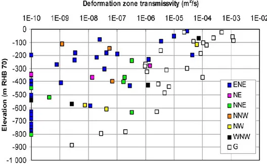
where T(z) is the deformation zone transmissivity, z is the elevation relative to sea level (RHB 70 datum), T(0) is the expected value of the transmissivity of the deformation zone at zero elevation, and k is a fitted parameter that can be interpreted as the mean depth interval over which transmissivity of a given zone decreases by an order of magnitude. A value k = 232.5 m was fitted based on data shown in Figure 1.1.
A single trend model is used for all sets of deformation zones, despite these statements (from R-09-20 p. 15) which suggest hydrologic distinctions among different sets:
The division of the deformation zones into major sets and subsets is useful from a hydrogeological point of view. Most of these structural entities are steeply dipping and strike WNW-NW, NNW and NNE-NE-ENE; one is gently dipping (G).
...
The highest transmissivities within the candidate area, regardless of depth, have been observed among the gently dipping deformation zones. The steeply dipping deformation zones that strike WNW and NW have, relatively speaking, higher mean transmissivities than steeply dipping deformation zones in other directions
When the data for each set of deformation zones are considered separately, the idea of a single trend with depth becomes questionable. For gently dipping zones (set G in Figure 1.1) and the steeply dipping ENE and WNW sets, a decreasing trend with depth is apparent. However, for the NNW set, the highest transmissivity is seen at the deepest measurement point. For the NE set, data are available only over a depth interval of about 100 m; the deepest measurement is intermediate to the two
shallower measurements. For the NNE set, three measurements points between -450 m and -800 m were below 10-9 m2/s, but the other four measurements, from about -240 m down to -630 m, are remarkably uniform in the range 2-4x10⁻⁷ m2/s . For the NW set there are just three measurements: a single high value at about -100 m, and two lower values near -600 m.
If data from above -150 m (i.e., within the range where tests are likely to be affected by highly transmissive, sub-horizontal sheet joints) are excluded, the gently dipping set is the only set that shows clear evidence of a trend with depth. The ENE set shows an increase in the proportion of tight sections below -600 m. However in the range -100 m to -600 m its dominant characteristic is a very wide scatter of transmissivity values, suggesting a high degree of heterogeneity.
Figure 1.1:Deformation zone transmissivity versus elevation for Forsmark (from R-09-20,
Figure 2.4; also in R-09-22 p. 20, Figure 2-6, both based on Figure 5-1 from Follin, 2008). Colored symbols refer to different sets of deformation zones with different nominal strike directions as listed in the legend; G represents gently dipping zones.
Thus the transmissivity data from deformation zones could just as well support an alternative interpretation in which only the gently dipping zones show a regular pattern of transmissivity decreasing with depth, while the steep zones are essentially random (dominated by heterogeneity which ranges over 5 orders of magnitude) in the interval -100 m to -600 m, then predominantly tight below -600 m. However, such an interpretation, or any other alternative to the assumption of a single trend with depth for all zones, has not been tested for SR-Site.
Besides influencing the overall understanding of groundwater flow at the site, insufficiently critical adoption of this single interpretation leads to other poorly supported conclusions, for example this one regarding stochastic, minor deformation zones that intersect the repository in certain realizations (R-09-20 p. 94):
Examination of the particle pathways show that the low Fr and tr values for
realisation 5 are associated with a single large, high transmissivity (about 1.0∙10–3 m2/s) HRD fracture that extends from the surface and intersects several
deposition tunnels near the main tunnel, as shown in Figure 6-20. In reality such a feature would have a depth dependent transmissivity which would reduce the flow associated with it at repository depth.
This is an unsupported statement, as no evidence has been presented for depth-dependent transmissivity in the minor deformation zones which are modelled
stochastically. The idea of depth-dependent transmissivity in these minor zones apparently derives from the inference of depth-dependent transmissivity in the major zones. Arguably such a dependency might exist, but SKB's programme has produced no evidence of it, nor is evidence cited from other subsurface investigations.
As noted by Follin et al. (2008) variability of approximately 2.5 orders of magnitude is observed laterally within individual deformation zones. In the SR-Site model this variability is represented by the simplest possible type of geostatistical model, in which a nugget covariance model is assumed for lateral spatial variability. This implies no spatial correlation of transmissivity above the scale of the finite elements in the model (which are mesh dependent). Tsang et al. (1996) demonstrated that spatial correlation of hydraulic conductivity in deformation zones can lead to large-scale flow channelling that can affect far-field radionuclide transport.
Results of SR-Site modelling (R-09-20 p. 130) further indicate that flows to deposition holes during periods of glaciation are structurally determined by clustering of deformation zones. This underscores the importance of understanding (or considering multiple alternative interpretations for) the hydraulic properties of deformation zones, the effects of glacial loading, and possible repetition of high flux areas during episodic advance and retreat of glaciers.
1.2.3.
Upscaling methodology
Upscaling from a discrete representation of bedrock fractures and deformation zones, to yield effective continuum properties for blocks on scales of 100 m or larger, is a central feature of the hydrogeological modelling effort for SR-Site. As noted in R-09-20 (p. 28):
… to model flow and transport on the regional-scale it is often necessary to consider larger-scale bulk properties in the context of an ECPM continuum concept. This requires methods (i) to convert the properties of a network of discrete fractures of lengths less than the continuum blocks into equivalent continuous porous medium (ECPM) block properties, ... and (ii) to represent larger scale features such as fracture zones by appropriate properties in a series of continuum blocks (the IFZ method).
The method for calculation of ECPM block properties from a discrete-fracture network (DFN)model, using the ConnectFlow code, follows a conventional method as described in R-09-20 (p. 30):
ConnectFlow uses six directional components to characterise the symmetric hydraulic conductivity tensor. Using the DFN flow simulations, the fluxes through each face of the block are calculated for each head gradient direction. The hydraulic conductivity tensor is then derived by a least-squares fit to these flux responses for the fixed head gradients.
The method in essence follows that of Long et al. (1982), who showed that valid tensors can be obtained for sufficiently dense and well-connected populations of fractures. As noted in R-09-20 (p. 30), the DFN-ECPM upscaling calculations for Forsmark did not make use of “guard zones.” Guard zones, as recommended by Long et al( 1982), are flow simulation domains slightly larger than the block size for which ECPM properties are being calculated (used to guard against overestimation of hydraulic conductivity due to fractures that cut across corners of a block).
The significance of not using guard zones is discussed in R-09-20 based on results for Laxemar, where a similar model showed that the effects were minor. However, as noted on p. 30:
The problem is most significant in sparse heterogeneous networks in which the flux through the network of fractures is affected by ‘bottlenecks’ through low transmissivity fractures, and is quite different to the flux through single fractures.
Since the water-conducting fracture system is inferred by SKB to be significantly sparser at repository depths for Forsmark than for Laxemar, this issue requires further evaluation.
An additional question, not addressed in SR-Site, is whether an effective hydraulic conductivity tensor is valid for the sparse networks that are inferred at Forsmark. Long et al. (1982) examined this in terms of goodness-of-fit statistics for the fitted hydraulic conductivity tensors. Goodness-of-fit statistics for the ECPM tensors computed by ConnectFlow for Forsmark have not been reported. If the fits are poor, this implies a system in which the ECPM upscaling will result in more uniform connectivity than the underlying DFN model, resulting in a less heterogeneous flow system with distributed rather than discrete pathways for transport.
Upscaling of the deformation zones (HCDs) is handled in ConnectFlow by a different method as described in R-09-20 (p. 41):
The IFZ method identifies which elements are crossed by a fracture zone and combines a hydraulic conductivity tensor associated with the fracture zone with a hydraulic conductivity tensor for the background stochastic network. For each element crossed by the fracture zone the following steps
are performed:
1. The volume of intersection between the fracture zone and the element is determined.
2. The hydraulic conductivity tensor of the background rock is calculated in the coordinate system of the fracture zone.
3. The combined conductivity tensor of the background rock and the fracture zone is calculated in the coordinate system of fracture zone.
4. The effective hydraulic conductivity tensor that includes the effect of the fracture zone is determined in the original coordinate system.
This method is appropriate for accounting for the contributions of transmissive features that are large enough to cut across a given ECPM block. The scientific consistency of this approach has been adequately demonstrated, for such cases. Block-scale porosities are calculated in ConnectFlow as a weighted sum of the pore space contained in connected fractures and deformation zones. The weighting is proportional to transmissibility (transmissivity times flow length of each feature). This is appropriate for transport calculations, as it gives an approximation of the fraction of porosity that is most likely to be encountered by solute moving through the dominant flowing features that are represented by an ECPM block. The choice of fracture aperture values, which are needed to calculate the pore volume of a given fracture, is a separate issue as discussed in Section 1.4.1.
The DarcyTools modelling software, which has been used for simulations of the construction & operation phase and for future permafrost and glaciation conditions (R-09-19 and R-09-21), uses a different method of upscaling DFN properties which is mathematically equivalent to that derived by Oda (1985). For large, through-going features it gives the same results as the IFZ method, but for smaller fractures it leads to an overestimation of the contribution to effective block-scale hydraulic
conductivity. This method has not been used for simulations with DarcyTools for SR-Site, according to R-09-19 and R-09-21. Instead, ECPM properties have been imported from ConnectFlow. This is an improvement over the methods used in previous applications of DarcyTools. However it is still subject to the issues described above, regarding DFN upscaling methods used in ConnectFlow.
The DFN models developed during SDM-Site are defined only for fracture domains covering a small part of the regional-scale model domain. For the hydrogeological base case considered in R-09-19 through R-09-22, the rock mass in the remainder of the regional domain is represented by a homogeneous continuum (plus regional deformation zones which are represented by the IFZ method as described above). The significance of using a homogeneous continuum on the regional scale was investigated by an “extended spatial variability case” based on DFN from
investigations at SKB's SFR site (R-09-20 p. 68-69). This DFN model was assumed to be valid throughout all portions of the regional-scale model domain that were not covered by the DFN models from SDM-Site. Although the applicability of the DFN data from the SFR for such a wide area is certainly doubtful, this gives a reasonable way of generating a stochastic ECPM for scoping the effects of block-scale
heterogeneity.
The conclusion, according to R-09-20 p. 68, is that the homogeneous CPM used in the base case “greatly reduces the effect of outcropping sub-vertical deformation
zones on particle exit points.” In other words, this feature of the base-case
hydrologic model tends to predict more dispersed discharge to the biosphere than is predicted by a model that incorporates a more realistic degree of variability throughout the regional-scale domain.
In simulations using DarcyTools (R-09-21), an ECPM representation is used for the rock containing the repository. The consequences of this representation for
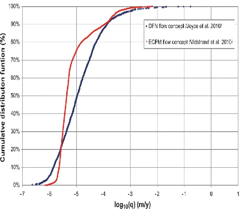
calculating flows to the repository are discussed in R-09-22 (p. 113). As seen in Figure 1.2, differences are seen in the distribution, primarily in terms of lower variance and a reduced fraction of deposition holes with Darcy flux higher than 10-5 m/yr. As noted in R-09-22, the tails representing the high values of Darcy flux are similar despite the differences for lower values. However, the most extreme flows, to the top one percentile of deposition holes (as represented by the blue symbols close to the top edge of the plot)are underpredicted by a factor of 10 to 100, by the ECPM representation.
The upscaling for the regional-scale ECPM model domain omits fractures with radii smaller than 5.6 m, but these are kept in site-scale and repository-scale flow. The practical reasons and consequences of this difference are well explained in R-09-20, so this is not an issue of concern for the safety assessment.
A novel “Equivalent Discontinuous Porous Medium” (EDPM) approach is discussed in R-09-22 (Chapter 4 and p. 109), with the suggestion that this is a preferable to the ECPM approach when inflow to individual deposition holes are considered in a low permeability environment. Further scientific scrutiny of this approach is needed to make sure that the improvements claimed are not simply artefacts of insufficiently accurate local solutions in a strongly heterogeneous ECPM model.
Figure 1.2:Cumulative distributions of Darcy flux at deposition hole positions for future temperate climate conditions, comparing results obtained from the simulations conducted with DarcyTools (ECPM representation) on a super-regional scale (red curve), and results from the simulations conducted with ConnectFlow (DFN) on a repository scale (blue curve). From R-09-22 (Figure 7-3).
1.2.4.
Treatment of channeling
Flow channelling is discussed in TR 11-01 and has been incorporated in past transport simulations for SDM-Site in terms of a “channelling factor” which effectively reduces the transport resistance of flow paths by a factor of 0.1. This approach is intended to account for the reduction in area that is available for matrix diffusion from fractures.
In SR-Site it is further argued (p. 138) that taking account of channelling by this approach is conservative since it does not take credit for the radial matrix diffusion from effectively pipe-like channels, or diffusion into stagnant zones of a fracture plane in contrast with the one-dimensional geometry of diffusion from a planar fracture. However, this argument overlooks the general scientific consensus (e.g. as documented by the RETROCK project)that channels in fractures tend to be broad in relation to the aperture. Hence the benefits of increased dimensionality for diffusion would be achieved only near the edges of a channel.
The main problem with the treatment of channelling in SR-Site, however, is that this is considered only as a modification to a network model that is derived and
calibrated in terms of a conceptual model of interconnected plate-like fractures, with uniform flow properties across each plate. Different results might be obtained if
channelling was assumed in the calibration process, as such a model would have different connectivity characteristics for a given set of fracture parameters.
1.3.
Adequacy of relevant models and data
Sources of information for key datasets, derivations of parameters, and mathematical models and assumptions are for the most part adequately documented to allow review. A few problems were encountered which are discussed in Section 1.6 in terms of transparency and traceability issues.
The use of multiple types of hydrogeological models (different software, scales, and mathematical conceptualizations) to account for different issues of concern for long-term site evolution leads to a need to manage and track data that are passed between models. For example, DarcyTools and ConnectFlow both use ECPM hydraulic conductivity fields that are calculated within ConnectFlow, but must be exported to DarcyTools. Flow calculations using ConnectFlow for detailed representations of the repository in the glacial case (R-09-20 p. 74-76) in turn depend on pressure & salinity fields which are imported from the DarcyTools model (R-09-21; R-09-22 p. 43).
In addition, use of multi-scale models with the ConnectFlow concept requires linkage between CPM/ECPM and DFN parts of the model (R-09-20 p. 32). This requires implementation of “internal boundary conditions” to ensure continuity of pressure and conservation of mass. These conditions appear to be appropriately handled, according to the descriptions, but the internal exchange of these types of data within model makes it more difficult to understand the characteristics of the individual parts of the models, for review purposes.
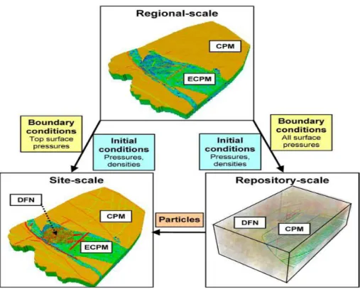
The key aspects of the multi-scale modelling approach used for the temperate period are summarized in Figures 1.3 and 1.4. Modelling time scales, flow and transport models, representations of repository components, and key input/output for each scale of model are summarized succinctly in Tables 3-1 and 3-2 of R-09-20. During particle-tracking to predict properties of transport paths, it was found (R-09-20 p. 43) that some particles exit the vertical sides of the repository-scale model. These were handled by restarting these particles from corresponding positions in the
site-scale model. Performance measures such as travel time are then calculated as
the cumulative travel-time along both legs of the path. While this approach is conceptually correct, it requires an additional level of bookkeeping which is not directly reported. Review of this and other ways in which data are exchanged between models on different scales may be worthwhile for subsequent, detailed review.
The two primary models (ConnectFlow and DarcyTools) differ their treatment of the physics of mass transfer of salinity between matrix and fractures and their
representation of dispersion (R-09-22, p. 46). The implementation in DarcyTools assumes that macrodispersion can be accounted for as a combination of
heterogeneity in the ECPM together with advection and diffusion, and that
dispersion on the sub-grid scale due to smaller-scale flow-field heterogeneity can be neglected. This assumption should be verified by reference to experiments on relevant in fractured rock.
Figure 1.3:Illustration of the concepts of model scales, embedding, and the transfer of data between scales (from R-09-20, Figure 3-9).
Figure 1.4:Modelling processes. Fracture generation is shown in green, regional-scale processes in pink, site-scale processes in yellow and repository-scale processes in blue. Outputs are shown in peach. Solid arrows indicate the modelling workflow within a scale and dotted arrows indicate a transfer of data between scales. From R-09-20, Figure 3-10.
1.3.1.
Particle tracking methods
The algorithms used for particle tracking vary in their representation of
macrodispersion, depending on the type and scale of model. In ConnectFlow (R-09-20 p. 34) dispersion is not simulated for portions of particle trajectories that pass through ECPM or CPM blocks. In other words, these parts of the trajectories are fully deterministic for a given flow-field.
However, within DFN portions of a model, a type of macrodispersion can result from probabilistic allocation of particles to outflowing branches of a fracture intersection. The algorithm allocates particles in proportion to the mass flux, which is equivalent to an assumption of complete mixing in the fracture intersections. This is likely justifiable for the low fluid velocities that are expected for post-closure temperate conditions. However, applicability for faster flows (such as may arise during glaciations) should be checked in terms of the Peclet number for flow through the fracture intersections (Berkowitz et al., 1994).
No dispersion is assumed to occur within fracture planes regardless of size (not justified in this report although it is supported for the case of variable-aperture fractures by previous SKB research by (Painter, 2006). No tortuosity of transport paths is assumed in the fracture plane; this is likely conservative.
According to R-09-20 (p. 79 ff) some particles do not reach the surface, either due to getting stuck in low-velocity areas of the calculated flow field or due to exiting a side boundary of the model. Particle tracks in some cases (e.g. R-09-20, p. 102, Figure 6-25) appear to show strong effects of the diagonal gridding scheme that is used in deformation zones. This might add artificial effects of tortuosity to the computed residence times and transport resistances, but the net effect is perhaps not significant since other (physically realistic) sources of tortuosity in fracture planes have been neglected.
1.3.2.
Abstraction of safety-assessment parameters
Formulae for calculating performance assessment parameters from the flow models and particle tracking output are described in R-09-22 (p. 30, p. 40).For a discrete model for sparsely fractured rock such as is apparently encountered in the repository target volume at Forsmark, Darcy flux and the equivalent flowrate, Qeq, are both in some sense nonphysical quantities as they depend on volumetric
averaging assumptions and/or diffusion parameters. While these parameters are needed as part of the interface to SKB's transport models, presentation of DFN results exclusively in these terms is an obstacle to understanding physical meaning of the results. The physically valid quantities in a DFN model are the mean water velocity in the fractures, or flux density per unit fracture width. Solute exchange with a leaking or corroding canister is presumably related to the ratio between the water velocity and the diffusion through water in the fracture. Presentation of the quantities that can be calculated directly from the DFN models would be helpful to present for better understanding of the results.
The formula for F factor (R-09-22 p. 40) includes two parameters for each path segment which are not clearly defined: Flow width wf and flow segment length. How are these defined for the general case where flow in the fracture plane is between
intersections with two other fractures that are not parallel to each other, and which may have different intersection lengths? How are these quantities defined for cases in which three fractures intersect at a single point? Illustrations to explain such cases would be useful as additional information for understanding the results.
When there are multiple fractures intersecting a deposition hole, Qeq for the Q1 path
is calculated as the sum of contributions of individual fractures (Qf/√af), divided by
the deposition hole length (R-09-22 p. 40). In such cases, is each of these fractures then also used as a source for particle tracking? Different units are used for the initial Darcy flux depending on the type of flow path, in order to determine whether to launch particles – does this quantity have a consistent physical meaning?
1.4.
Handling of uncertainties
Although many relevant uncertainties related to hydrology have been identified, analysed, and discussed in sufficient detail, a few areas where further analysis is needed are discussed in the following subsections
1.4.1.
Uncertainty in fracture transport aperture
In the approach used for data analysis and groundwater flow modelling for SR-Site, the discrete-fracture network model is parametrized in terms of fracture
transmissivities rather than fracture apertures. This is reasonable as fracture
transmissivity is more directly related to what can be measured by hydraulic tests in boreholes. However, fracture apertures are needed to relate groundwater flux to advective velocities and water residence times for transport modelling.
According to R-09-20, two different mathematical models relating transport aperture
et to fracture transmissivity T have been used. In the hydrogeological base-case model, the following relationship is used (R-09-20, Equation 6-1):
et = 0.5T
0.5
The authors note that the coefficient 0.5 has been rounded from 0.46 (the value used in SDM-Site (Follin, 2008). For sensitivity studies, a second relationship based on a compilation of Swedish tracer test data by Hjerne et al. (2010) has been used (R-09-20, Equation 6-2):
et = 0.28T0.3
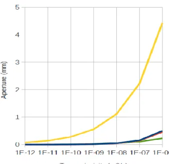
These relationships are plotted in Figure 1.5 together with the “cubic law” which is the expected relationship between aperture and transmissivity for laminar flow of water through an idealized parallel-plate fracture which has a perfectly uniform aperture. It is apparent that the Hjerne et al. (2010) model gives the highest apertures, particularly for the higher transmissivity fractures, while the cubic law gives the lowest apertures. The rounding of the base-case model's coefficient from 0.46 to 0.5 is seen to have very little effect.
Figure 1.5:Comparison of alternative relationships between fracture transmissivity and fracture transport aperture.
Considering that both the base-case model and the Hjerne et al. (2010) model are empirical models fitted to different sets of experimental data, it is doubtful that these bound the range of reasonable possibilities. The cubic law gives consistently smaller apertures than either of these empirical models, and thus yields shorter water residence times for a given transmissive network. On the other hand, the cubic law also gives a higher ratio of wetted surface per unit volume water in the fractures, which offsets the effect of shorter travel times in terns of F factor (transport resistance) calculations.
Other alternative relationships could include stochastic relationships between transport aperture and transmissivity (rather than a perfect correlation), or different relationships for different fracture sets depending on their orientation.
The Hjerne relationship gives about an order of magnitude increase in median water residence times, compared to the hydrogeological base case (R-09-20 p. 94). Thus the consequences of assuming one model or the other for transport aperture can significantly affect predictions of groundwater velocities. The sensitivity to a wider range of alternatives, including stochastic relationships, should be explored to determine if there are plausible relationships that could lead to an effect on residence times greater than the observed order-of-magnitude effect.
1.4.2.
Uncertainty in flow model
In addition to uncertainties in the parametrization of major deformation zones (HCDs), there are residual uncertainties related to the derivation and parametrization of the DFN component model. The SR-Site main report claims (TR 11-01, p. 128) that there is high confidence based on consistency between different types of hydraulic data. However, it is also noted that flow rates measured by tracer dilution method are sometimes much higher than expected (TR 11-01, p. 128).
R-09-20 (p. 26) mentions comparisons against three sets of confirmatory data: • transient, large-scale cross-hole (interference) test responses,
• steady-state, natural (undisturbed) groundwater levels in the uppermost 150 m, and
• hydrochemical observations in deep boreholes
However, the number of transient, cross-hole tests were limited (number of data and sensitivities should be discussed), as were first-strike, undisturbed groundwater pressure measurements from the deep bedrock.
The use of hydrogeochemical data for reference water fractions to check the site-scale model calibration is innovative but leaves questions regarding the significance of deviations which are observed both in terms of reference water fractions and the depths at which transitions are observed. The latter are perhaps the most important for checking the understanding of the site-scale flow system, but receive little discussion and tend not to be highlighted by the methods of presentation. R-09-20 (p. 26) further notes that:
[T]he performance of the groundwater flow model, which was based on
equivalent continuous porous media (ECPM) properties, was slightly improved if the anisotropy of the horizontal to vertical hydraulic conductivity ratios of the upscaled values for both the Quaternary deposits (HSD) and the fracture domains (HRD) were increased compared with the upscaled values derived from the initial structural-hydraulic settings.
This implies that the model was adjusted to improve the fit, rather than simply using the data to test the model. The way in which this adjustment was performed is not clearly reported in the documents covered by this review.
1.4.3.
Use of stochastic realizations and variants
Multiple stochastic realizations and hydrogeological model variants have been used to investigate key uncertainties. Ten realizations of the model with semi-correlated size-transmissivity model for DFN fractures and stochastic properties in the hydraulic conductor domains were propagated through the safety assessment chain including probabilistic central corrosion cases, in addition to a single DFN
realization which used laterally homogeneous HCD properties. (Data Report Section 6.7; TR-11-01 p. 654-655). Additional model variants were used to test the
consequences of adding additional “possible” deformation zones, the effects of varying tunnel properties, the effect of boreholes arising from human intrusion, and effects of glacial conditions including effects on tunnel properties under glacial conditions. A concise summary of the cases analysed for the temperate case and glacial case is given in Table 4-1 of R-09-20.
Glacial case variants with elevated EDZ transmissivity are found to be significant for Q2 & Q3 flows (R-09-20 p. 122). A variant that includes a transmissive path through the crown space of tunnels reduces Q2 but enhances Q3. Little effect on Q1 is seen for either EDZ or crown space variants. Similar effects are seen for EDZ properties in combination with the temperate case (R-09-20 p. 114).
Simulations of the construction and operation phase considered three different levels of grouting efficiency (R-09-19; R-09-22 p. 46-47). However only homogeneous grouting efficiency is considered (or homogeneous grouting to one level in the rock mass, and to another level in deformation zones intersecting the repository). Heterogeneous grouting might not be important for the major predictions of R-09-19, such as overall drawdowns of meteoric waters, upconing, and resulting changes in water chemistry around the repository. However, it might contribute to
heterogeneity of flows to deposition holes during the resaturation period. In the glacial case calculations reported in R-09-21, the glacial case without permafrost produces the largest hydraulic gradients at the ice sheet margin, hence the greatest effects on Darcy flux and fracture (advective) salinity at repository depth. All variants are based on a uniformly advancing ice sheet. One question to consider for further review is whether a lobed glacial front in combination with localized absence of permafrost could yield more severe consequences in terms of hydraulic gradients and focussing of flow through the repository.
A discontinuous permafrost layer ahead of a glacier is considered in R-09-21, using probable locations for taliks (unfrozen spots in the permafrost layer) which are estimated from a forecasted landscape development model for Forsmark. A question is whether talik locations can be sufficiently well predicted by this approach to bound the uncertainties, or whether a more stylized approach should be used to complement this. Uncertainty in the occurrence of taliks is discussed in the climate report (TR-10-49) but only in generalized terms.
1.5.
Safety significance
Are the safety functions, indicators and criteria adequately defined and meaningful with respect to geosphere variables that can be measured or reliably calculated? Safety functions, safety function indicators and safety function indicator criteria are summarized in Figure S-7 of TR-11-01 (p. 26). Safety functions that are closely related to hydrogeological interpretation and modelling are discussed in order of their appearance in this figure.
1.5.1.
Safety Function R1. Provide chemically favourable
conditions
The chemically favourable conditions (Eh; salinity; ionic strength; concentrations of HS-, H2, CH4, organic C, K+ and Fe; pH; Cl-) are all functions of flow system in
combination with chemical transport and buffering reactions in the naturals system. Reducing conditions (R1a) are judged to be maintained (TR-11-01 p. 29) on the basis that “Local, temporary penetration of oxygen to repository depth cannot be
excluded during hydrologic transients caused by passage of an ice sheet margin but the effects are too small to influence safety.” Key hydrologic issues that relate to this
safety function thus concern the duration and magnitude of hydrologic transients associated with the passing of an ice sheet margin.
The concept of flow channelling may be significant for assessing this safety function, since channelized flow may enhance the penetration of glacial meltwaters with less chance for buffering by the rock matrix. In SKB's Site Descriptive Model, channelling is applied as a factor for transport after deriving and calibrating a HydroDFN based on assumption that the full fracture plane participates in flow. Would calibration of a channelized model lead to very different results for penetration of glacial meltwaters to repository depths?
1.5.2.
Safety Function R2. Provide favourable hydrologic
and transport conditions
Both of the subcriteria for this function, to provide high transport resistance (F) in fractures and low equivalent flow rates Qeq at the buffer/rock interface, are direct
functions of the hydrogeological model and especially the DFN component that represents the relatively unfractured rock between deformation zones.
This issue encompasses processes that could affect the DFN network and its interactions with the rock matrix, over long time periods that must be considered for safety assessment. Matrix-fracture interaction on large time scales as well as EDZ connectivity effects and evolution of the excavation-influenced zones are both relevant. Key questions for a comprehensive review include:
Is there sufficient understanding and/or exploration of how EDZ affects local connectivity, as the EDZ and excavation-influenced zone evolve during construction, operation, and post-closure stages?
Are there plausible scenarios that could affect DFN connectivity as well as flow, and if so have these been adequately considered?
The effects of the climate phases considered in SR-Site on Darcy flux to deposition holes are well summarized by a figure from R-09-22 which is reproduced in Figure 1.6. From this it is seen that the situation of greatest concern that has been evaluated so far is glacial advance without permafrost, followed by glacial permafrost
situations.
1.5.3.
Safety Function R3. Provide mechanically stable
conditions
Subcriteria for this safety function include limited groundwater pressure which is a function of groundwater flow but primarily a function of overburden stress. The other subcriteria (shear movements and shear velocity at deposition holes) are primarily a function of earthquake scenarios which are at best indirectly related to groundwater flow. However, there is overlap with hydrogeology in terms of methods for avoiding large fractures and minor deformation zones.
1.6.
Quality in terms of transparency and
traceability of information
Transparency and traceability in hydrogeological modelling for SR-Site suffer from many small problems which, when taken individually, generally do not detract significantly from confidence in the results of the calculations, but collectively lead to concerns that should be addressed. The following are noted as examples. TR 11-01 (p 137) states that “Less than 4% of realizations below 400 m exhibit connectivity of any kind,” but does not indicate what block scale this finding pertains to.
According to R-09-20 (p. 41) a minimum block conductivity and porosity is set for any elements that have zero values of these properties following the fracture upscaling and IFZ methods. It is stated that “appropriate minimum properties were
derived in the SDM Hydro-DFN studies by calculating the minimum values seen when the DFN is truncated only at very small fractures relative to the block size, and so are essentially free from the truncation effect.” However, these minimum values
are not stated.
According to R-09-20 (p. 26) the performance of the groundwater flow model based on ECPM properties,
was slightly improved if the anisotropy of the horizontal to vertical hydraulic conductivity ratios of the upscaled values for both the Quaternary deposits and the fracture domains were increased compared with the upscaled values derived from the initial structural-hydraulic settings.
However, the magnitude of this adjustment is not documented in this report nor in R-09-22.
According to R-09-20, the base-case model relating transport aperture et to fracture transmissivity T is (Equation 6-1):
et = 0.5T0.5
The authors note that the coefficient 0.5 has been rounded from 0.46 (the value used in SDM-Site (Follin, 2008). However, R-09-22 (p. 24) gives the original expression without rounding the coefficient:
The values of the parameters a and b in Equation 2-5 used in SDM-Site are defined in /Dershowitz et al. 2003/, where a = 0.46 and b = 0.5. /Stephens et al. 2007/ provide values of the geologic thickness of all deterministically modelled deformation zones.
R-09-20 further states that:
The kinematic porosity of the deformation zones was not investigated. In the groundwater flow modelling, values of the kinematic porosity were calculated from the ratio between the transport aperture and the geological thickness. The transport apertures were calculated from the transmissivities of the deformation zones (see Eq. (2-1) in /Follin 2008/ and Eq. (3-17) in Section 3.2.2) and the values of the geologic thicknesses were provided by /Stephens et al. 2007/.
However the referenced Equation 3-17 does not exist in this report, and Eq. 3-5 on p. 41 is introduced as:
The transport aperture, et, of each fracture that represents a DZ is calculated as:
et = Φ b
where Φ is the porosity and b is the thickness of the deformation zone at that point, as specified by the geologists.
which appears to be a case of circular reasoning. It can further be noted that geological thicknesses do not always correspond to the hydrologically active portions of deformation zones. Correct equations are eventually given on p. 30 of R-09-20.
Follin (2008, p. 32) gives the original form of the equation:
For the sake of the SDM, the kinematic porosity, ne, was derived based on the
underlying hydrogeological DFN calculated element-by-element as the total connected volume divided by the element volume. The fracture volume for an individual fracture was calculated as the fracture area within an element multiplied by the transport aperture, and this is modelled based on Äspö Task Force 6c results /Dershowitz et al. 2003/, which assumes a direct correlation between the transport aperture et and the transmissivity T, such that:
et = 0.46 T0.5
But then go on to say (bold text added):
Although this approach provides a direct link between the assignment of kinematic porosity in the ECPM model and the underlying DFN model, it relies on several approximations, including that the full fracture surface area
contributes to advection and that the contribution to porosity of fractures below the truncation of fracture sizes in the regional DFN model is not significant.
Hence, the derived kinematic porosity using Eq. (2-2) was used as an initial guess to the calibration, and adjustments were made as part of the calibration to help inform the description of the fracture transport properties.
This leaves a question as to whether these “adjustments” are reflected in SR-Site calculations.
As a separate issue, in the discussion of boundary conditions for the SR-Site temperate-stage hydrogeological model (R-09-20 p. 55), the following is stated [with comments added in bold-face in square braces]:
The boundary conditions used for SR-Site were the same as those used for SDM-Site. They consisted of a recharge-discharge boundary condition [with what
values?] on the top surface and no flow through the sides [how justified?] and
bottom of the model. The bottom of the model also had a hydrochemical
boundary condition set to the initial values of the reference water mass fractions
[not given here, but found in Section 6.2]. The reference water mass fractions
on the top boundary varied with time according to the elevation of shoreline with regard to the topography of the ground surface [where found?]. The initial conditions were also the same as those used in SDM-Site, except as noted in Appendix C.
As a self-standing reference document for SR-Site, this report should reiterate all values that are carried forward from previous site-modelling work, rather than