Akademin för Innovation, Design och Teknik
Analysis of the propeller shaft program
at Volvo Construction Equipment
Master thesis, Product Development KPP305
30 credits, D-level
Product and Process Development Master of Science in Engineering Programme
Innovation and Product Design
Annika Henrich and Nadja Suonperä
Presentation date: 15 June 2012
Commissioned by: Volvo Construction Equipment Tutor (company): Carl Fredrik Wangenborn
Tutor (university): Bengt Gustafsson Examiner: Rolf Lövgren
Abstract
Volvo Construction Equipment’s driveline development department initiated this thesis work. It was calculated for two students working for 20 week period of time, which equals 30 hp each. The reason for Volvo CE to start the cooperation was the large number of variance of companion flanges and propeller shafts generating additional work for several departments within Volvo.
The problem statement consisted of questions, which should result in information about the number of variants and combinations of propeller shafts and companion flanges used; the reason for the quantity of variants and what factors are affecting the choice of propeller shafts and companion flanges. They should also give answers to how article reduction can be implemented and what recommendations can be given to Volvo for the future.
Using a Gantt chart as a planning tool helped the working process to progress in a structured way. Different methods of data collection were done to secure the problem understanding. Tools such as a literature review, function diagrams, and interviews were used to complete the data collection. Co-workers from the purchasing department and the part number reduction team were interviewed. Besides the in-house contact an opportunity was given to interview the suppliers during visits at their factories.
Computer software was used as a resource of confirming information and mapping currently used components. The mapping process resulted in interesting findings, which were further researched. Together with the information from the interviews, reasons for the variety of used components were clarified. To deepen the problem understanding a more detailed variation mapping was made, showing what driveline components were generating most variants of companion flanges.
The findings made and the recommendations received from the suppliers were unitized in a best case scenario. The questions from the problem statement were analyzed and answered. The recommendations given regarding to Volvo Construction Equipment’s propeller shaft program included guidelines for modularization. The success of modularization is based on among other factors, on particular documentation, continuous communication and close cooperation with the suppliers. This report can be defined as the first step towards a modularized propeller shaft program for Volvo CE’s haulers and wheel loaders.
Acknowledgements
We want to thank Carl Fredrik Wangenborn, our tutor at Volvo Construction Equipment, for his support during the whole working process. We are grateful for his availability for weekly meetings and help. We also want to thank everyone else at Volvo CE for sharing their knowledge with us. We are thankful to have had Bengt Gustafsson as a tutor at Mälardalen’s University. Many thanks, to all of you for joining us on our journey.
Thank you!
2012-06-04
Nadja Suonperä Annika Henrich
Vocabulary
Arkivator Companion flange supplier located in Falköping Part number reduction Decreases the variety of part numbers
Articulated hauler Construction equipment for material handling such as transportation and dumping, also named hauler
Articulation point Joint in the centre of the machine that allows the wheel axles to move from being in a parallel position
Bogie axle Wheel axle pair spreading load to decrease the stress
CAD Computer Aided Design
CAST Common Architecture Shared Technology
Cogs Teeth on gears that distribute torque to the next gear Cog wheel Gear
Commonality Coordination of objects on common characteristics
Companion flange One of two parts that form the connection between different parts of the driveline
Concept Suggestion for a problem solution
Cross serrated Pattern of splines locking the propeller shaft to the companion flange in a concentric position
Crown wheel Ring gear interacting with the pinion and differential gears Differential Unit that allows the wheel pairs to rotate at different speed Differential carrier Gear that transfer the torque to the wheels
Differential housing Casing surrounding the differential
Differential lock Locks the wheel pairs to rotate at the same speed
Driveline Structure of all components that together drive the vehicle Dropbox Splits and distributes torque
Dust cover Cover that protects the companion flange from dust ENOVIA SmarTeam Volvo database, also named SmarTeam
Factor of safety Ratio between yield strength and estimated maximum stress Function diagram Tool for identifying a product’s main, sub and support functions Gantt chart Planning tool to coordinate recourses on project activities Hub reduction Unit that increases the torque
ISO standard International standards for all kinds of subjects, in this case design guidelines
Joint angle Allows angle variation between the propeller shaft and other components
Mapping Create an overview of a process or current information Mechanics Type of companion flange for shorter connections
Meritor Supplier for differential carriers and companion flanges, located in Lindesberg
Modularization Combining modules by using common interfaces Oscillation Cyclic variation
Over dimensioning Increase the dimensions and consequently the factor of safety Part number Identification number for a product in a range
Pinion Cog wheel interacting with the crown wheel in a differential Post market Management of spare parts
Propeller shaft Rotating shaft transmitting the engine power to the point of application
PROST Product Data Management system
Rear Back part
RPM Rates Per Minute
Set-up cost Cost caused by the set-up time
Set-up time Time needed to prepare machines for the next job Spicer Nordiska Kardan Supplier for propeller shafts, located in Åmål
Splines Slot pattern used in connections for transferring torque Standardization Reduce varieties through standards to simplify a process Strength category Classification based on a machine’s power and dimensions Target specification Document consisting of requirements
Torque The ability of a force to move an object about an axis Transmission Controls the rotational speed and torque by gear ratio Volvo CE Volvo Construction Equipment, also named Volvo Volvo PROSIS Volvo database, also named PROSIS
Wheel loader Construction equipment for material handling such as loading and carrying
Table of contents
1. INTRODUCTION ... 9 1.1BACKGROUND ... 9 1.1.1 The company ... 9 1.1.2 Products ... 10 1.2PROJECT DIRECTIVES ... 121.3PROBLEM STATEMENT AND OBJECTIVES ... 13
1.4DELIMITATIONS ... 13 1.5DOCUMENT OVERVIEW ... 14 2. THEORETICAL BACKGROUND ... 15 2.1HAULER DRIVELINE ... 15 2.2PROPELLER SHAFT ... 22 2.3COMPANION FLANGE ... 23
2.4SPICER NORDISKA KARDAN ... 24
2.5ARKIVATOR ... 25
2.5.1 Processing of companion flanges ... 25
2.6COMPUTER SOFTWARE ... 26
2.6.1 PROST ... 26
2.6.2 Volvo PROSIS ... 26
2.6.3 ENOVIA SmarTeam ... 26
2.7MAPPING ... 27
2.8PART NUMBER REDUCTION ... 27
2.8.1 Standardization ... 27 2.8.2 Modularization ... 28 2.8.3 Integration ... 28 2.9CAST ... 28 2.10OVER DIMENSIONING ... 30 3. METHOD ... 31 3.1GANTT CHART ... 31 3.2LITERATURE REVIEW ... 32 3.3INTERVIEW ... 32 3.4TARGET SPECIFICATION ... 32 3.5FUNCTION DIAGRAM ... 33 3.6DESCRIPTIVE OBSERVATION ... 33 3.7CONCEPT GENERATION ... 33 3.8CONCEPT SELECTION ... 35 4. APPLIED METHODOLOGY ... 36 4.1INTRODUCTION ... 36 4.1.1 Planning ... 36 4.1.2 First information ... 36 4.2PROBLEM ORIENTATION ... 37 4.3DATA COLLECTION ... 39 4.3.1 Computer software ... 39 4.3.2 Purchasing ... 41
4.3.3 Supplier visit at Spicer Nordiska Kardan ... 41
4.3.4 Supplier visit at Arkivator ... 42
4.3.5 Results of supplier visits ... 44
4.4ANALYSIS OF COLLECTED DATA ... 45
4.4.1 Mapping ... 45
4.4.2 Findings ... 49
4.4.3 Conclusions ... 51
5.3IMPLEMENTING CAST... 59
6. ANALYSIS ... 61
7. CONCLUSIONS AND RECOMMENDATIONS ... 68
7.1CONCLUSIONS ... 68
7.2RECOMMENDATIONS ... 68
7.3REFLECTIONS ... 69
8. REFERENCES ... 70
Appendix 1 Master thesis description Appendix 2 Gantt chart
Appendix 3 Planning report Appendix 4 Mapping tables Appendix 5 CAST-template
List of figures
Figure 1 Articulated hauler
Figure 2 Wheel loader
Figure 3 Hauler driveline
Figure 4 Wheel loader driveline
Figure 5 Driveline of a hauler
Figure 6 Front bogie axle casing
Figure 7 Differential housing
Figure 8 Wheel movement in a curve
Figure 9 Differential
Figure 10 Differential locking
Figure 11 Tooth contact between the crown wheel and the pinion
Figure 12 Differential carrier
Figure 13 Hub reduction
Figure 14 Final drive
Figure 15 Propeller shaft
Figure 16 Propeller shaft parts
Figure 17 Propeller shaft application in a wheel loader
Figure 18 Possible angle range
Figure 19 Cross serrated companion flange
Figure 20 Mechanics companion flange
Figure 21 Component swapping modularity
Figure 22 Component sharing modularity
Figure 23 Method flow chart
Figure 24 Simplified Gantt chart
Figure 25 Simplified Function diagram
Figure 26 Five steps in concept generation
Figure 27 Propeller shaft Function diagram
Figure 28 Companion flange Function diagram
Figure 29 Illustration of a hauler driveline
Figure 30 Examples of illustrations from PROSIS
Figure 31 Short propeller shaft between the dropbox and the front wheel axle
Figure 32 Driveline of A25F
Figure 33 Driveline of A40F
Figure 34 Two types of transmission companion flanges
Figure 35 Companion flange attachment methods
Figure 36 Variation of companion flanges spread over driveline components
Figure 37 Component sharing modularity
Figure 38 Best case of companion flange usage
List of tables
Table 1 Supplier comments
Table 2 Propeller shaft mapping
Table 3 Companion flange mapping
1. Introduction
This chapter gives a short introduction and describes the background of this thesis work, for the Master thesis description, see appendix 1. An initial description of the company is given and the problem statement and objectives are presented. The project directives are listed and the delimitations made are also clarified in this chapter. On top of that an overview of the document is given.
1.1 Background
Hard competition increases the importance of identifying all parts affecting efficiency and costs. A large number of variants is both time-consuming and expensive. Therefore is part number reduction a significant variable of efficiency.
Within Volvo Construction Equipment’s propeller shaft program there are approximately 20-25 different variants of companion flanges. The corresponding program for Volvo Trucks consists of 4 companion flanges. The large number of variants at Volvo CE is partly due to the lack of coordination during the development and purchasing of components such as axles, transmissions and dropboxes.
1.1.1 The company
Volvo Construction Equipment is a successful part of AB Volvo that operates in the construction industry. Volvo CE has a 180 years long experience within construction equipment with its main roots in Eskilstuna Mekaniska Verkstad. To reach the point where Volvo CE is today, several companies have been merged and acquired. AB Bolinder-Munktell became a part of AB Volvo in 1950; shortly thereafter they introduced their first wheel loader. A few years later their first articulated hauler was launched. Today Volvo CE’s product range consists of: Articulated haulers Wheel loaders Backhoe loaders Excavators Motor graders Milling equipment
Tracked forestry carriers
Pipelayers
Demolition equipment
Pavers
Compactors
Volvo CE is a global company that is active in large sections of Europe and also in China, Brazil and USA etc. The factories in Sweden are located in Eskilstuna, Arvika, Braås and Hallsberg. In Eskilstuna’s factory transmissions and axles are manufactured, to be sent to Arvika; the wheel loader manufacturing and Braås where the articulated haulers are produced. The driveline development is also a part of Volvo CE in Eskilstuna. Volvo CE’s major suppliers for propeller shaft and companion flanges are Spicer Nordiska Kardan and Arkivator (Volvo Construction Equipment, 2012).
1.1.2 Products
The machines of Volvo Construction Equipment’s product range that have been in focus during the thesis work were the articulated haulers and the wheel loaders.
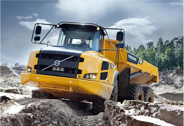
Articulated hauler
Volvo CE’s articulated haulers come in four different sizes, A25F, A30F, A35F and A40F. The term for the machines consists of three identification characters. As an example A25F, A for the machine type, articulated hauler, 25 for the machine size, and F for product generation. The haulers are designed to handle the tough conditions when working with mining, earthmoving, tunnelling, quarrying, material and waste handling. A typical work cycle for a hauler consists of loading, moving, manoeuvring and dumping. Figure 1 illustrates an articulated hauler.
Figure 1 Articulated hauler
Volvo’s unique steering system allows high steering force at a low engine speed. This is necessary for the hauler’s working environment in e.g. deep mud. The design of the hauler’s body and the high tipping angle support efficient material ejection. To withstand the required oscillation and have good ground contact in tough operating conditions; the hitch allows independent movement of the tractor and the trailer. The haulers are equipped with differential locks; dog clutches. When locked, all wheels rotate at the same speed for maximising the tractive power (Volvo Construction Equipment, 2011).
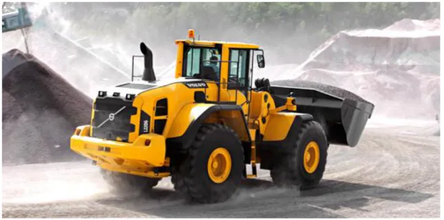
Wheel loader
Volvo CE’s wheel loader range reach from mini loaders to large production machines. The wheel loaders are suited for work in load and carry operations, earth moving, civil and building constructions, agriculture, landscaping and more. The figure 2 is a picture of a wheel
Figure 2 Wheel loader
Volvo’s patented lift arm system gives best possible breakout torque and parallel movement, through the whole lifting range. The wheel loaders are equipped with an intelligent load-sensing hydraulic system that provides exact required power, regardless of the engine rpm. The long wheel base allows the wheel loader to move safely and comfortably on rough ground. Volvo CE provides their customers with a wide range of attachments to the wheel loaders (Volvo Construction Equipment, 2009).
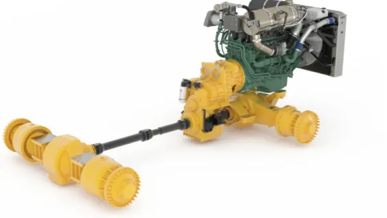
Driveline
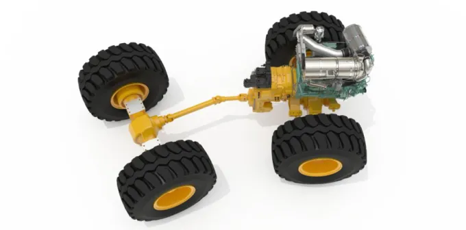
Figure 3 shows how the articulated haulers driveline is designed. The engine is placed in the front part of the driveline. The engine torque is transmitted through the transmission to the first propeller shaft that is located between the transmission and the dropbox. From the dropbox the torque is distributed to the front wheel axle through a short propeller shaft and to the bogie axles through three propeller shafts in line. A propeller shaft is placed between the front and rear bogie axle. As described the hauler driveline consist of 6 propeller shafts. The companion flange functions as the connection between the propeller shafts and other components or for that matter, other propeller shafts. Therefore, there are 19 companion flanges in a hauler’s driveline. The odd number of companion flanges depends on that one of the companion flanges, at the hauler’s articulation point, is connected to a brake disc and therefore lacks a companion.
The wheel loader driveline, see figure 4, differs significantly from the hauler driveline. In the wheel loader the engine is placed in the rear part of the machine. The function of distributing torque between the front and rear wheel axles is integrated in the transmission, making an external dropbox redundant. Between the transmission and the rear wheel axle is one propeller shaft, and between the transmission and the front wheel axle there are two propeller shafts in line. This means that the wheel loader driveline includes 10 companion flanges; 5 connections between propeller shafts and other components.
Figure 4 Wheel loader driveline
1.2 Project directives
The thesis work was to be made at the Product Development department at Volvo Construction Equipment in Eskilstuna. The given working spaces were equipped with computers with the needed computer software installed. The working spaces were placed close to the different working groups of the driveline design. It was not required to spend all the working hours at the company. The time could also be used for further research and report writing at the university. A weekly meeting with the tutor at Volvo CE was defined as a fixpoint in the project plan, where the progress was presented and questions discussed. The given directives from the company were:
Obtain basic knowledge about propeller shafts
Mapping of existing programs at Volvo Trucks and the suppliers Arkivator and Dana Spicer
In consultation with representatives for axle and transmission development suggest common interfaces
1.3 Problem statement and objectives
The large number of variants of companion flanges generates additional work for several departments within Volvo; design, purchasing, production, service and post market. A development project has been initiated that aim to develop a new transmission platform. Parallel to this a review of today’s propeller shaft program is about to get started. These two projects give a good opportunity to create a modularized propeller shaft program. If the axle and transmission development can agree on common interfaces, it might be possible to reduce the variety of companion flanges.
A. How many variants and combinations of propeller shafts and companion flanges are used?
B. What are the differences and similarities between the variants of the two components?
C. What is the reason for the quantity of variants?
D. What other factors are affecting the choice of propeller shafts and companion flanges? E. How can the part number reduction be implemented?
F. What recommendations can be given to Volvo CE to avoid problems concerning the large quantity of variants?
The objective of this master thesis is to investigate the possibilities of part number reduction for Volvo CE’s propeller shaft and companion flanges, used in haulers and wheel loaders.
1.4 Delimitations
The thesis work is calculated for two students full-time working in a 20-week period of time and equalling 30 hp/student.
After mapping of the existing propeller shaft program the thesis work should result in several suggestions for part number reduction for propeller shafts and companion flanges. The work is delimited by the idea of using the same products Volvo CE is using today, but in a smaller variety and not introduce additional variants to avoid unnecessary introduction costs. The goal is to analyse and compare the different variants and investigate the possibilities of modularization. The modularization process will be limited by the shortage of time for this thesis work and therefore focus on recommendations and function as a pre-study for the further process steps. The master thesis will not result in a finalized solution, but in recommendations, in which direction the modularization work should progress.
During the working process the large range of products, in form of different machines, were divided into different groups. The groups differ in how detailed the research is done and how clearly they are highlighted in the documentation in this report. That partially depends on the access of information or the possibility to deepen the research and analysis, instead of getting a wide but superficial knowledge. The detections that will be made are going to be compared and controlled by looking at all the machines that are not included in the group focussed on. That ensures that the conclusions are correct and can be applied onto all machines without problems or disadvantages.
1.5 Document Overview
2. Theoretical background – The theoretical background of the master thesis is presented.
3. Method – A description of the tools and methods used during the thesis work is given.
4. Applied methodology – The applied methodology is presented and an explanation of how the different tools and methods were used is given.
5. Results – The results of the thesis work are presented.
6. Analysis – An analysis of the results is given that answers to how the problems are solved.
7. Conclusions and recommendations –The conclusions drawn from the work and the recommendations for the future are presented.
8. References – The references used are listed.
9. Appendix – Important documents that complement the report are listed.
2. Theoretical background
The master thesis is based on the theoretical background presented in this chapter. Topics that have been important input for the work has been to take a closer look at a driveline, facts about propeller shafts and companion flanges, information about Volvo CE’s main suppliers Spicer Nordiska Kardan and Arkivator, but also the manufacturing process of the companion flanges. An introduction of the computer software used is given and more detailed descriptions of mapping, part number reduction and over dimensioning is included in this chapter. In addition to that, CAST, an example of a modularization project within Volvo is described.
2.1 Hauler driveline
The hauler driveline is a bit more complex than the wheel loader’s. Therefore, a closer look at this type of driveline was made. The description is structured from an overall picture of the driveline to more detailed explanations of the functions.
Figure 5 Driveline of a hauler
Figure 5 shows an overview of the articulated hauler’s driveline. The engine is placed in the front part of the driveline. The engine torque is transferred through the transmission to the first propeller shaft. The propeller shaft is placed between the transmission and the dropbox. The dropbox’s function is to distribute the torque to the front wheel axle through a short propeller shaft and to the bogie axles through several propeller shafts lined up. The front and rear bogie axles are connected to each other by a propeller shaft. In total, hauler drivelines consist of 6 propeller shafts. The companion flange functions as the connection between the propeller shafts and other components or for that matter, other propeller shafts. Therefore, there are 19 companion flanges in a hauler’s driveline.
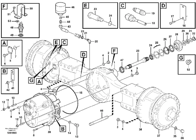
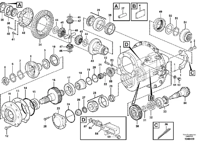
Figure 6 Front bogie axle casing
The hauler has six wheels and therefore three wheel axles. The wheel axles are similar to each other, except that the front bogie axle includes a torque splitting transfer gearbox that enables torque split between front and rear bogie axles. The exploded view, figure 6, shows a front bogie axle casing (1) where all components are integrated. The visualization contains a differential carrier (39), the axle casing (1) and the outgoing axle (23) that is connected to the propeller shaft between the front bogie axle and the rear bogie axle. The hauler’s wheels are assembled outermost of the axle casing.
Figure 7 Differential housing
The differential carrier already mentioned is shown in the exploded view, in figure 7. The differential carrier splits the torque and transfers it to the wheels and further to the rear bogie axle to activate the rear wheel drive. This results in all wheel drive. The components lined up in the upper part of the differential housing transfer the torque to the outgoing axle. The torque is also transferred to the rear axle, as mentioned above, by the tooth contact between gear (16) and (30). Gear (30) is connected to the pinion, which through the crown wheel transfers the torque to the hub reduction, explained later. Since the hauler is equipped with all-wheel drive, the differential’s function is to allow the wheels to rotate at a different speed. This function is used when the hauler is turning. In a turn, the outer wheels are forced to travel a longer distance within the same time interval and are necessarily rotating at a higher speed.
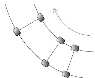
The period of time (t) the wheels are rotating is the same for all wheels. Since the distance (s) for the outer wheels gets longer in a turn, the velocity (v) must increase to compensate for the variance in distance. This phenomenon is visualized in figure 8.
Figure 8 Wheel movement in a curve
When the driveshaft, with axle shaft side gear (45) connected to the outer wheels rotates at a higher speed in a turn, the differential gears, number 47, start to rotate along the crown wheel. Figure 9 describes how the components in a differential interoperate with each other.
Figure 9 Differential
In opposite, non-driven wheels do not need individual speed adjustment because they are not connected to each other and just follow the movement.
Figure 10 Differential locking
When driving in slippery conditions, differential locking mechanism and the all-wheel drive engagement makes it possible to lock the differential function and therefore force the wheels to rotate at the same speed and transfer torque to the wheel with best traction. Figure 10 shows an exploded view of a differential locking system.
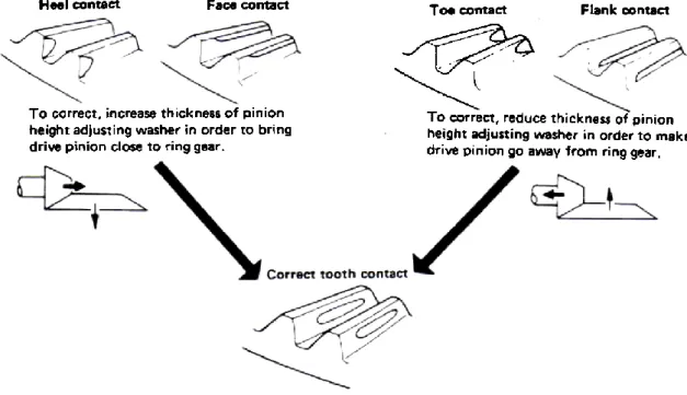
To ensure the optimal tooth contact between the pinion and the crown, in a differential, wheel a testing in form of color marking is made. The marking shows how well the tooth contact is adjusted. The figure 11 illustrates the correct tooth contact and how incorrect contact patterns can be adjusted.
Figure 11 Tooth contact between the crown wheel and the pinion
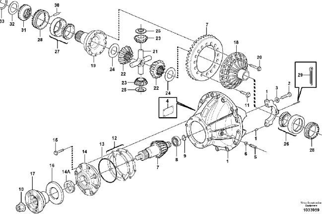
The differential carrier in the front and rear axle are very similar and demonstrated in figure 12. The companion flange is placed on the left side, marked with number (17). The companion flange is connected to the pinion with a nut in the centre. The sealing is also included in the connection, number (14A). To adjust the position of the pinion, a shim kit is used that control the distance, how far the pinion is inserted into the casing of the final drive. The distance varies by the number of rings used in the shim kit.
Figure 12 Differential carrier
The hauler is also equipped with hub reductions which give an additional increase of the torque, see figure 13. The planetary gear, placed in the hub retainer, is responsible for the hub reduction. A planetary gear consists of a sun gear (11), connected to the drive shaft from the differential, a planet carrier (13) where the planet gears (14) are placed. A ring gear (17) is concentrically put around the planet gears. In most cases one of the three main components is fixed and the other gears function as input and output (Olsson, 2006). The gear ratio varies depending on which of these options the gears are responsible for. If the planet carrier is defined as output gear reduction is caused. That means that a higher torque, than the torque coming from the sun gear, is transferred to the wheels. If two of the components are locked together, it leads to direct drive without gear ratio (public.resource.org, 2010).
The hub retainer also includes a brake system consisting of several brake plates and brake discs, also shown in figure 13.
Figure 13 Hub reduction
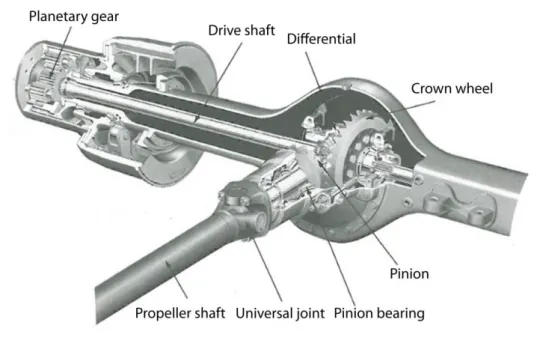
To summarize the interaction of all functions integrated in the final drive an overview is given in figure 14, (after Olsson, 2006, p.391). The figure also shows the connection between the propeller shaft and the differential by the universal joint. The most important parts are named in the figure.
2.2 Propeller shaft
A propeller shaft, figure 15, is used as a connection between different components of a driveline to transfer torque, sometimes called drive shaft. The benefits of using a propeller shaft are that it allows movement of the components connected to each other. A field of application can be the connection between wheel axles in construction equipment when the machine operates on a rough ground. A propeller shaft tolerates differences in length and angles. The function is enabled by an assembly of several parts. The fastening between the driveline components is possible due to the use of companion flanges.
Figure 15 Propeller shaft
A general propeller shaft consists of approximately 12 different parts. Figure 16 shows all the parts included in a propeller shaft. The flange yokes are the parts of the propeller shafts that are connected to the companion flanges on transmissions or wheel axles. The flange yoke, the journal spider and the tube yoke together form one of the propeller shaft’s joints. Inside the joint there is a bearing that is fixed in its position with the circlip. The tube yoke is welded to the tube. Inside the tube, sometimes a cardboard roll is placed to reduce noise. The sleeve muff is also welded to the tube. Inside the sleeve muff there are splines, where the yoke shaft with external splines can slide along. This gives the propeller shaft the possibility to handle differences in length. Over the yoke shaft there is a cover tube. The yoke shaft together with the journal spider and the flange yoke form the other joint of the propeller shaft.
Figure 17 illustrates the benefits of using propeller shafts in a wheel loader. The propeller shaft joint angles allow the wheel loader to move the wheels axles from being parallel to each other. The wheel loader is designed for movements of up to 40˚ in both directions from the straight starting position.
Figure 17 Propeller shaft application in a wheel loader
Figure 18 is a simplified illustration of the possible range of angle variation for a wheel loader, due to the propeller shaft’s joint that is placed at the machine’s articulation point.
Figure 18 Possible angle range
2.3 Companion flange
The term companion flange describes the type of flange that fits together in a relation to another flange. In general, all loose flanges that are not integrated with an equipment body are named companion flanges. It consists of a sealing surface and a pipe thread entrance. The companion flange connects the propeller shaft with the transmission or other axles. The dimensions can vary depending on their use (Woodcousa, 2012).
Briefly, a companion flange can be defined as a pipe flange, which is threaded on the inside to receive a pipe length. It is also drilled, to ensure the connection to another equal flange (Merriam-Webster, 2012). The bolt holes that align with another flange are a trait of
companion flanges (Wisegeek, 2012). Two different parts of a shaft can be coupled together by using companion flanges.
In Volvo CE’s haulers and wheel loaders, two main types of companion flanges are used. The most common type is the cross serrated companion flange and the other is a companion flange called mechanics. The mechanics companion flange is often used when there is not much room for a propeller shaft. Using mechanics companion flanges, instead of cross serrated, allows the propeller shaft to be slightly longer, since the mechanics companion flanges are shorter. Figure 19 shows a cross serrated companion flange and figure 20 a rough 3D-model of a mechanics companion flange. Volvo CE’s main supplier of companion flanges is Arkivator, but they also have some other smaller suppliers such as Meritor, Officine Mecchaniche Piemontesi in Italy, and the German supplier ZF Friedrichshafen AG.
Figure 19 Cross serrated companion flange Figure 20 Mechanics companion flange
2.4 Spicer Nordiska Kardan
One of the world leaders in the supply of driveline products such as axles, driveshafts, off-highway transmissions, and sealing and thermal-management products is the Dana Holding Corporation (Dana, 2010). In the corporation is the company Spicer Nordiska Kardan AB included, with about 135 employees. Spicer Nordiska Kardan has their plant in Åmål, which they have had since it was built in 1973. They produce driveshafts for both off-highway and commercial vehicles. Approximately 165 000 shafts are delivered per year to customers like Volvo Truck Corporation, Volvo Construction Equipment, and Scania, mainly located in Europe and Brazil. Major features of the propeller shafts include its high resistance to dynamic load variations, large deflection angles, and uniform load distribution throughout the axial displacement range, low rotational diameter, low weight, and versatile flange connections. These features provide an ideal base for standardized driveline design and new power transmission concepts. Spicer Nordiska Kardan has been a supplier for Volvo CE since 1950. (Spicer Nordiska Kardan, 2012).
2.5 Arkivator
Arkivator AB is a Swedish technology company that manufactures products in businesses like telecom, machine, and vehicles. It was founded in 1940 and has today about 600 employees. The factories and offices are placed in Sweden, Hungary, and China. The company is divided into three different parts; Arkivator Telecom that develops and manufactures telecom and broadcasting products, Arkivator Machine Systems that is responsible for the development and production of machines for the global packaging industry, and Arkivator Industry for machining by automated and manual processing.
Arkivator Industry produces complex products in all existing materials using machining methods. They also assemble and test the products and offer everything from prototypes to large series production of both small and large components. The processes are modern and précised to high quality standards because of the customers demand of excellent quality, delivery precision and efficiency. Some of these customers are Tele2, ABB, Haldex Group, Tetra Pak, and Volvo CE (Arkivator, 2012). The main components that are ordered by Volvo CE are companion flanges. The capacity for this section of the manufacturing is set to a volume of 190 000 parts/year in two shifts. Arkivator Industry in Falköping produces 130 000 companion flanges each year. A volume of about 50 000 is delivered to Volvo CE.
2.5.1 Processing of companion flanges
The step in the manufacturing process at Arkivator that affects the costs the most is induction hardening. Induction hardening is a process where metal components are heated using induction heating and afterwards quenched, to reach a change in the material structure that increases the brittleness and hardness of the material. The hardness gives the component more strength to resist demanding and remaining deformation (Andersson, 2007). Inductive hardening is chosen if only selected areas of the component should be processed to accomplish the best result. The heat is generated directly in the part by high-/low-frequency alternating current in an electromagnetic coil (copper coil). The heating rate is typically 300-1000°C/s. After the heating treatment follows a rapid cooling by sluicing with municipal water, aquatensid or quenched in oil. Stabilizing is a common last step but not mandatory. This kind of hardening is used for parts up to 200 mm in diameter without limits regarding the length. Inductive hardening generates compressive stress in the surface and increases the strength of the component. The hardness ranges from 600 to 800 HV (Vickers) (Induktionsvärme AB, 2012).
In this case the induction hardening is used to strengthen the companion flanges. Advantages of this treatment that are used are that it can be applied on certain sections located on the component, it is easy to repeat and the whole process is comparably environmentally adapted (Induktionsvärme AB, 2012).
2.6 Computer software
The independent research and information retrieval were mainly done by the use of different kinds of computer software that are integrated in the general working process of Volvo CE. Under this heading are several computer programs described which were taken advantage of to get needed information.
2.6.1 PROST
PROST is a Product Data Management system where most of Volvo Construction Equipment’s products are documented. PROST is an acronym for PROduct STructure. In PROST information such as parts, drawings, products, bills of material, and engineering change notices. The software is divided into several subsystems. All subsystems are a collection of transactions (a command consisting of 5 letters) that are formed after a logical structure. Information about cost, part- and drawing information, document changes, and historical structures can be found in the subsystems (Isene PDM, 2001).
PROST was used during this thesis work for orientation in the product structures.
2.6.2 Volvo PROSIS
Volvo PROSIS 2011 is a combination of spare part catalogue, workshop service manual, electrical wiring diagram, hydraulic diagram and information about maintenance of all Volvo Construction Equipment models.
Volvo PROSIS consist all types of construction equipment produced by Volvo CE. PROSIS is a shortening for describing PROduct Support Information System. The program has a user-friendly search function that gives fast results of information linked to the part number or other search options. It is also possible to create an order in the program and save this as a file, a copy, attached to an e-mail or print it (On Board Diagnostic, 2012).
In this thesis work Volvo PROSIS was used to get an overview on the drivelines and the connection of the included components.
2.6.3 ENOVIA SmarTeam
The program SmartTeam is specialized in collaborative Product Data Management (cPDM) and makes it possible to overlook all data linked to one product within the companies work. The data can consist of information about material and dimensions in technical drawings or 3D-parts in cooperation with CAD software like CATIA. ENOVIA SmarTeam offers flexible product data management that promotes cross functional cooperation. SmarTeam can be used of both large and small companies that have departments in several countries. The version used was a web based variant. The part number functions as input to get to the information. Besides the direct data of the item the related data is listed as well. In this case SmarTeam was used to receive technical drawings that were reliable and complete as a base for comparison and discussion (Combinum, 2011).
2.7 Mapping
Information mapping is one of the elements that are included in scientific methods. The information that is used is documented and processed in a user defined way. This kind of method was introduced by Robert Horn in the 1960’s. To fit the information for use, its objective is defined and the need of the user analysed. The collected data is sorted out to cut the inessential information. For simplifying the management and applicability of information for any person of interest, it is presented in an appropriate way in form of figures, pictures or diagrams that supports the written elements. Visualisation makes it easier to understand and interpret the given information and use it in further steps of a working process (Horn, 1992). Another type of mapping is process mapping. At Landstinget Västernorrland (2010) this implementation is divided into four different steps. Before starting the mapping, an appropriate process should be identified and selected. The process frames and limits should be determined; defined where the current process starts (input) and ends (output). The customers and their expectations should be identified.
The four steps are listed below:
1. Describe the process in its present state: define the different activities that form the process, sort the activities along a timeline, and draw the process by using telling symbols.
2. Validate the process map by showing it to a person that is not active involved in the mapping design. Correct and complete the picture to avoid confusion.
3. Describe the process in ideal case and compare it to the current process to identify problems and deficits and to visualise potential for improvement. Find out what elements that are value adding for the process.
4. Deepen the analysis of the process to the different stations in the process and control how the flow chart is affected by potential problems. Introduce tools like check lists or templates.
2.8 Part number reduction
The introduction of new products causes direct and indirect costs. The costs named indirect can vary between different companies and the involved departments like administration, design, purchasing, and service. Every of these departments are spending time and effort in the introduction process. Another kind of costs that arises at a new introduction of a product is costs caused by support and service during the product’s lifecycle. In most cases are the products in production about seven years, causing different costs (Nilsson, 1990).
There are three different methods used for part number reduction: standardization, modularization and integration. The subsequent part will give a short description of the mentioned methods.
2.8.1 Standardization
Standardization describes the successful process of introducing standards and guidelines for a developing process or a product’s design and condition. Standards that are broadly accepted and well-reasoned can help to ensure the needed quality and the properties that are needed
for assemble different parts. The shape and function of a product is adjusted in a structured way, to make it easier to control if the product implements the requirements in the most effective way (Supplement Quality, 1999). Standards and regulations make it easier to communicate between several departments, to clarify what guidelines to follow.
2.8.2 Modularization
The term modularization means to divide a large problem or product into smaller subparts. That makes it easier to understand the function and the influence of the modules on the whole assembly, building the final product. The modules can be combined individual depending on the problem to be solved and the customer needs. This affects all involved departments economically. The volume of each produced module part has the possibility to increase, because it can be used in different places. Other aspects that change with modularization are delivery time and complaint. Even the post market is easier to control because it is easier to identify the modules causing problems (Nilsson, 1990).
Scania CV AB is known as a good example of consequently using modularization within product development. Over 60 years of experience in modular products, has now led to a product range that can easily be adjusted to the customer needs. For Scania modularization is not only for lowering production costs, due to a small number of components, but also for shortening the time to meet customer needs and the demands of new legislation. They point out that modularization must not be mistaken as standardization, since customized solutions are offered to their customers. When using standardized interfaces between components in the powertrains and transmissions, allows development and changing of components without affecting other surrounding components at the same time. Working with modularization gives Scania an opportunity to break into new segments in a cost-effective way (Scania Value, 2009).
2.8.3 Integration
Integration in context with product manufacturing describes the integration of products even in other sectors or components in other assembled products. That means that the same part can be used in several areas. The result can be larger volumes of one kind of part and consequently lower costs (Nilsson, 1990).
2.9 CAST
Volvo CE is continuously working with development of their products and the manufacturing process. A project that supports the development in the company is CAST. CAST stands for Common Architecture Shared Technology and describes the modularization process for different projects. The information about the CAST projects was given by one of the employees at the CAST platform by a presentation and a complementary interview and discussion.
One of the main reasons to start with the CAST project was the large amount of parts included in Volvo CE’s range of products. Today Volvo CE has approximately 175 000 part numbers documented. Looking at Volvo Trucks segment and comparing the number of just 5000 part numbers with the 175 000 part numbers of Volvo Construction Equipment, made them aware of the potential of improvement. Obviously is it not possible to compare these two segments
functions. But the handling of parts and the way of modularization can be investigated and possibly be adopted to the construction equipment as well.
The first project was a modularization project for the cabs for the different construction equipment. Mapping the existing cabs showed that there were 48 different kinds of doors and only three of them have the same handle. Further there were several differences in the design of the cab doors, like different solutions for the sealing, the lock system, and the profile of the door frame. That means there were different solutions, in different machines, for the same function. The variation of parts also resulted in a large variety in the manufacturing process. The CAST Technical Solution method includes reduction of variation by using the same materials, components, sealing, frame profiles and manufacturing methods, for example. This made it possible to manufacture 8 kinds of cabins on the same production line. They differed in dimension, shape and looks but the production includes the same steps and use of mounting equipment. The CAST Technical Solution method is divided into six steps, as shown in the list below.
Scope
Requirements
Describe different technical solutions Make evaluations
Test and verification Documentation
First the scope is defined by deciding what function a common solution should be found for. The requirements on the solution for the function are specified and relevant technical solutions described. Existing solutions from present products, applicative and interesting solutions from other areas and competitors are analyzed. This step should be followed by a structured evaluation of the solutions to find the preferred and best matching solution for the function in question. The proposed CAST Technical Solution is tested as much as possible and all steps in the process are documented and the choices made are motivated. The documentation is one of the most important steps to make it possible to use the information for further projects or further development and adjustment. It should be able to transfer the knowledge and findings in between different employees, departments or organizations. That prevents inventing the wheel several times. A template for the documentation is attached to the report, see appendix 5. The template was also used for this project and results are presented in chapter 5.3 Implementing CAST.
There are different types of design linked to modularization and function commonality. At integral design are all functions integrated in one variant and adjustments and changes or addition of functions requires development of new variants. Another principle is the modular design which is based on the possibility to combine several modules. A module is defined as a building block containing a specific function and a well-defined interface. To the same main module different components can be added because of a common interface, see figure 21.
Figure 21 Component swapping modularity
Modularization can also describe the case of using the same component in different products. These products are sharing the same components but can differ in the whole, see figure 22.
Figure 22 Component sharing modularity
As a summary, the Common Architecture Shared Technology can be described as a method to coordinate the large amount of part numbers and discover synergies and similarities. This enables to reduce the amount and make the production process less complex and complicated. The goal of modularization is to be more efficient and make more with less. That includes more product variants but less part numbers; less work to introduce product updates, new functions and generations; reuse of existing solutions for more products and a modularized product allows separated development, preassembly and pre-testing.
2.10 Over dimensioning
A product is defined by a great amount of dimensions and other characteristics like material and color. In the developing process the dimensions are chosen based on guidelines of design, function and safety.
To over dimension a product means to increase specific parameters to change the products dimensions. The change is not needed to ensure the products functionality. There can be different reasons to use over dimensioning in the design of a product. One reason is to get an advantageous factor of safety. The factor of safety is a term used to describe the ratio between the yield strength and the estimated maximum stress, in ordinary use. That means it gives an indication of how safe the structure will work under the specific condition.
By over dimensioning the thickness of material or the size of the product in general the factor of safety can get a higher value and prevent upcoming problems and reduce risks. Another reason to over dimension a product or product part can be that this action enables the use of the same part in several models or machines. That happens by using the bigger variants of parts even in smaller desings. The advantage of it is that the amount of different parts needed to assemble the whole range of machines is reduced. That means you can use the over dimensioning as a tool for part number reduction and lower unnecessary costs and parts in
3. Method
In this chapter are all tools described that were used as a support under the working process. The information how to use the tools is completed by their positive and negative effects on the project. The solution process with all included steps is visualised as a flow chart in figure 23.
Figure 23 Method flow chart
3.1 Gantt chart
There are many different aspects included and resources needed in a product development process. To organize these it is important to get an overview. A Gantt chart, see appendix 2, is a common planning tool that shows all activities that must be performed to reach the goal of the project, within the time frame. The activities are placed in an order that shows how they interact. Some activities cannot be started before others are done, for example. The timeline shows what amount of time is available. Responsibility for the activities is given to several members of the project group. It is necessary to update and control the chart constantly under the working process, to overlook the estimation of timescales. This makes shortage of time or other resources clear and allows modification of the planning chart (Ulrich & Eppinger, 2008).The figure 24 shows a general example of a Gantt chart.
Figure 24 Simplified Gantt chart
3.2 Literature review
The literature review helps to reach a more detailed knowledge in the area in question and to get the basic understanding needed to continue the work. It is possible to get information about former work that has been done or discover gaps in the abundance of information. A literature review is conducted by gathering relevant information from various sources within the field of interest. According to Rydberg (1997); videos, sound recordings and photos are all included in this category. According to Hart (1998), a literature review is about selecting available documents on the research topic that contain ideas, data, information, and written evidence from a specific standpoint. The information found in the documents aims to express certain views on the nature of the topic. An effective evaluation of these documents, in relation to the research being proposed, is also a part of the literature review.
3.3 Interview
In order to describe, formulate hypotheses, and predict something an interview can be made (Ejvegård, 2003). During an interview information can be gathered that was not found in a literature review (Rydberg, 1997). The most common method in the research context is that an interviewer asks one respondent at a time. It is important to give a short introduction at the beginning, to give the respondent an impression of the project. An unstructured interview is defined by a spontaneous development during the conversation and the choice of questions can differ (Ejvegård, 2003).
3.4 Target specification
A target specification is used as an agreement between the client and the supplier. The specification describes the expectations and communicates the common aim for the project. It should be updated under the working process, in connection with the increasing knowledge or with changes in the project (Karlsson, 1996). The document contains all the registered customer needs. The expectations and needs of the customers are clarified. That shows what functions or characteristics the product should have to please the buyer. The requirement needs to be written in a way that can be understood of every participant (Bergvall & Demblad, 2003). That means that the language used is natural language, to avoid misinterpretations (Berndtsson, 2010).
3.5 Function diagram
A function diagram clarifies what functions should be included in the product. The various functions are divided into different categories depending on their significance. The central function is called main function and is reached by adding sub-functions and support functions. This kind of ranking visualizes the importance of the different features. It shows only what should be included in the product, but not how. Figure 25 shows a simplification of a function diagram.
Figure 25 Simplified Function diagram
3.6 Descriptive observation
A study visit is a useful method of getting a better understanding of a specific process. According to Routio (2007), a descriptive observation means studying and gathering of information with the aim of describing what happens during a process. The description shall not be affected by the observation; the findings should be the same without the presence of the observer. Ejvegård (2007) means that the advantage of an observation is that the researcher gets the opportunity to really understand the process. The disadvantage is that the observer might affect the process with his/her presence. It is of great importance to distance oneself from the task, to avoid subjective evaluation of the results. Several study visits with observations were conducted among suppliers, to get a deeper understanding of their manufacturing process and the collaboration between them and Volvo CE.
3.7 Concept generation
In Ulrich and Eppingers book Design and development (2008) concept generation is described as a five-step method. The five steps are presented in figure 26. A concept is a rough description of a products function, technology, and appearance. It has to answer the question in what way the customer needs will be satisfied. A concept is often presented as a sketch or a simple 3D model with a descriptive text. Since concept generation is relatively inexpensive and not as time-consuming as the rest of the product development process, it is valuable to carefully work through the concept generation process, in order to avoid expensive mistakes later in the process. If concept generation is carefully made, the development team should feel confident about exploring all alternatives. The quality of a final product depends a lot on the particularity of the concept generation.
Figure 26 Five steps in concept generation
The first of the five steps, clarify the problem, is about creating a mutual and general understanding of the problem to be solved. During this step it is useful to decompose a complex problem into simpler sub problems.
The next two steps in the process are the research parts, searching externally and internally. The external search consists of discovering already existing solutions to the problems, since it is cheaper than exploring completely new ones. Gathering external information can be interviewing experts and lead users, searching for patents and published literature, but also benchmarking of related products.
Searching internally is the most creative part of concept generation. To generate solution concepts, the team members’ qualifications in terms of knowledge and creativity is used. It is important not to take any unconsidered decisions. A consequence of product concept decisions is something that has to be lived with for a long period of time. Generating as many ideas as possible is preferred, and also welcoming all kinds of ideas, even those that may seem infeasible from start. It can be beneficial to have both individual and group sessions for concept generation.
The fourth step in the concept generation is exploring systematically. This means that the group systematically organize and combine the solutions they have found, to the sub problems, during the internal and external search. The aim is to sort out and categorize, to make the comparison between solutions simple. During systematic exploring, the solutions can be combined in concept combination tables to get an idea of which combinations are available.
The last step in concept generation; reflect on the solutions and the process, is about finding out if all possible solutions have been explored, if the group members have welcomed every
the authors have chosen to have this step as the last step in the process, they point out that it is important that the group reflects on the process during the whole work.
The advantages of a structured concept generation method, regarding to the requirements of this master thesis, are that the large number of influencing factors is taken into consideration and to ensure that nothing is forgotten. Although it is necessary to generate a lot of ideas, it is important to not only focus on the quantity, but also the quality. This kind of concept generation method was suited to use during this thesis work because it was important to, in an early stage, understand the problem to be solved. A lot of valuable information could be found when searching both internally and externally and exploring the solutions systematically gave a good overview of the possible concept combinations.
3.8 Concept selection
According to Ulrich and Eppinger (2008), concept selection is a process that progress during the whole development process. Concept selection is about evaluating the concepts developed during the concept generation. The concepts relative strengths and weaknesses are compared and the concepts are classified based on how well they satisfy the customer needs. The evaluation should result in one or several concepts worth further studying, development, or testing.
Some concept selection methods are considered to be subjective. However, there are structured selection methods that help the concept selection to be more objective. Different selection methods are listed below:
• External decision: An external person, such as a client, makes the selection. • Personal taste: An influential member of the development team selects a concept
based on personal taste.
• Intuition: The decision is made on what feels good.
• Multivoting: Every member of the team votes on their favorite concept and the selection is based on which concept that got most votes.
• Pros and cons: The team lists the advantages and disadvantages of every concept and makes a choice based on that.
• Prototype and test: Prototypes of every concept are made and tested, and the selection is based on test data.
• Decision matrices: Every concept is rated and weighed against predetermined selection criteria.
To be able to find the concepts that optimally fulfill the customer needs, a method that clarifies the strengths and weaknesses is needed. The concept selection methods used in this thesis work were external decisions, made by the tutor at the company after discussing the pros and cons between different possible solutions.
4. Applied methodology
The following chapter clarifies the used methodology and gives an explanation of each step done to push the project forwards. The headings chosen for this chapter are sorted in a logical order to make it easier to follow the progress of working process. This chapter gives an explanation of how tools and methods were used in this project.
4.1 Introduction
This introduction describes the first steps of the project, including the planning of the working process and the first information collection, together with an introduction at the department.
4.1.1 Planning
The planning of the thesis work started already before the actual date, at a meeting at Volvo CE with the mentor. The goal of the cooperation and the included milestones were discussed and a first time schedule was sketched up. This sketch was used as basic data to make a detailed planning report, see appendix 3 and Gantt chart, see appendix 2.
The planning report was written about two weeks after the beginning. Parts that were included in the report were the objectives, directives and delimitations of the project, literature that would be used for research and choice of methods. In addition to that a time management in shape of a Gantt chart was made. The project plan showed all activities that were required to reach the goal of the work.
The steps were sorted in logical order and linked to the time line. The resources such as time and manpower were divided to the process activities. Some of the activities were interacting and performed simultaneously. An example could be the data collection and problem understanding. By getting more input of information, increases the knowledge and the problem understanding can be more detailed. By understanding the problem, the data needed is clarified. The expected time consumption was followed up by the actual outcome. That eased it to discover shortage of resources and made it easy to modify the further working process. Shortage of time was also caused by illness, marked with a red color in the Gantt chart, see appendix 2, of the group members and the lost time had to be compensated. Some of the activities needed more time than expected and some less than planned. The project plan included two phases of data collection, analyzes and conclusions to allowed time to get back to the problem statement and adjust the needed information, to ensure a complete solution that made the process more effective.
In the Gantt chart and project plan was even a fixed point included each week, to meet the tutor and discuss the working state and get answers to questions and help in general. The steady contact with the mentor pushed the project forwards and ensured that the work progressed as wanted.
4.1.2 First information
The first week into the project contained information about the department for driveline systems at Volvo CE. Introduction material was handed out to present the products and
of the machines; wheel loaders, motor graders and articulated haulers, to more detailed explanations of the included components. General information about propeller shafts and companion flanges was also given, in form of instructions for design of propeller shafts and prior work that has been done within the subject.
This theoretical introduction was supplemented by a visit at the workshop and inspection of the machines in full scale. The goal was to get a picture of how the components are integrated into the complete machines and to get an idea of the dimensions.
To get in contact with the co-workers, appropriate for this thesis work, a contact list was obtained. The list contained the co-workers names and their special fields. That made it possible to know quickly who could answer what specific questions to improve the project work flow.
4.2 Problem orientation
To familiarize with the problem that had been presented as the reason why the thesis work was initiated, required plenty of work. Even though a lot of information was given during the introduction, a deeper understanding was needed. Much of the work in the beginning of the thesis work was about obtaining basic information regarding propeller shafts and companion flanges, to get an understanding about the problems related to the work.
4.2.1 Interview
Of course there was a lot of knowledge among the co-workers at the department where the thesis work was made, but it appeared that it was a bit disseminated and challenging to locate. There was not one person that had all information needed, but everyone knew something that would have an influence on the work.
Due to this, a number of interviews were conducted with different people, to get an idea of what kind of knowledge they possess, but also to learn more about the basics in the area. Several interviews where made with different people, during the first two weeks, within their special fields. Interviews were made with experts on companion flanges, expert on details like cogs and cog wheels, but also with the lead engineer of axle design. The interviews conducted were unstructured because it was not clear from the beginning what kind of information that would be interested. The questions asked were more spontaneous and occurred during the conversation. Focus was on letting the interviewees to talk about their work, in relation to the thesis work. The interviews gave answers about how they see the large number of parts from their perspective, whether they thought that it was a problem or not.
The conclusions that could be drawn from the interviews were that it was clear that no one have been responsible of dealing with the problems of large product range. It was confirmed that the large number of parts based on decisions that had been made in the history. The interviewees described that the development of the components in the driveline was divided between different departments in the past, which has led to lack of coordination and communication. Today they have to live with the consequences of the decisions made early in the development process.