Topology Optimization of Gear shifter
Housing and Contact Benchmarks.
Naresh Kalidindi
Mohamad Fardmoshiri
Topology Optimization of Gear shifter Housing and Contact
Benchmarks.
Naresh Kalidindi
Mohamad Fardmoshiri
This thesis work is performed at Jönköping Institute of Technology within the subject area Product Development and Materials Engineering. The work can also be a part of the master’s degree.
The authors are responsible for the given opinions, conclusions and results. Supervisor: Niclas Strömberg
Credit points: 30 ECTS credits Date: 26/08/2010
Abstract
1
Acknowledgement
1
List of figures
2
Summary
List of figures
3
List of figures
Figure 01: Geometry, boundary conditions and draw direction. 10
Figure 02: Optimized component . 11
Figure 03: Color contour of element density. 11
Figure 04: Geometry extracted from OptiStruct. 12
Figure 05: Geometry and boundary conditions and draw direction. 13
Figure 06: Manufacturing constraint with no draw direction (left) 14
and with draw direction (right).
Figure 07: Flow chart diagram of optimization process [1]. 16
Figure 08: A system of two linear elastic bodies in unilateral contact [12]. 17
Figure 09: Housing top layer. 21
Figure 10: Housing bottom layer with design (blue) and non-design (red). 22
Figure 11: Housing rigid links (red) surrounding the hole. 22
Figure 12: Constrained at rigid links inside the hole in (x, y and z) in all 23
directions.
Figure 13: Manufacturing constraints (z-axis). 24
Figure 14: Geometry benchmark 1. 25
Figure 15: Geometry benchmark 2. 26
Figure 16: Geometry benchmark 3. 26
Figure 17: Housing bottom layer optimized. 27
Figure 18: Optimized bottom layer IGES. 27
Figure 19: Solid layer of component CAD model 28
(two layers one component).
Figure 20: Bottom view of CAD model (two layers one component). 28
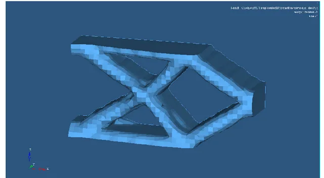
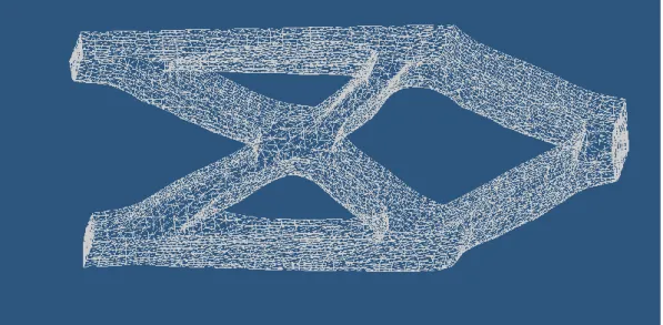
Figure 21: Solid layer of component (two layers one component). 29
Figure 22: Stress analysis of optimized component. 29
Figure 23: Bottom view of stress analysis of optimized component. 30
Figure 24: Displacement of optimized component. 30
Figure 25: Benchmark 01 2-D symmetry geometry [12], TOPO4ABQ, 31
symmetry no contact condition, load case:1 (vertically downwards).
Figure 26: Benchmark 01 2-D HyperWorks, no contact condition, 31
List of figures
4
Figure 27: Benchmark 01 2-D TOPO4ABQ, symmetry [12], 32
contact condition, load case: 1 (vertically downwards).
Figure 28: Benchmark 01 2-D HyperWorks, contact condition 32
load case:1 (vertically downwards).
Figure 29: Benchmark 02 2-D TOPO4ABQ [12], no contact condition, 33
load case: 2 (vertically downwards and upwards).
Figure 30: Benchmark 02 2-D HyperWorks, no contact condition, 33
load case: 2 (vertically downwards and upwards)
Figure 31: Benchmark 02 2-D TOPO4ABQ [12], contact condition, 34
load case: 2 (vertically downwards and upwards)
Figure 32: Benchmark 02 2-D HyperWorks, contact condition, 34
load case: 2 (vertically downwards and upwards)
Figure 23: 2-D TOPO4ABQ [12], contact condition, 35
load case: 1 (vertically downwards).
Figure 34: 2-D HyperWorks, contact condition, 35
List of tables
5
List of Tables
Table 1: Magnesium material properties. 21
Table of Contents
6
Table of Contents
Topology Optimization of Gear shifter Housing and Contact
Benchmarks. ... 1
Acknowledgement ... 1
Summary ... 2
Key words ... 2
List of figures ... 3
List of Tables ... 5
1
Introduction ... 8
1.1 BACKGROUND ... 81.2 PURPOSE AND AIMS ... 8
1.3 DELIMITS ... 8
1.4 OUTLINE ... 8
2
Theoretical background ... 9
2.1 OPTIMIZATION PROBLEM ... 9
2.1.1 Design variables for topology optimization [13] ... 10
MANUFACTURABILITY FOR TOPOLOGY OPTIMIZATION... 12
2.2.1 Minimum member size control [13] ... 12
2.2.2 Maximum member size control [13] ... 13
2.2.3 Draw direction constraints for topology optimization [13] ... 13
2.3 RESPONSES ... 14
2.3.1 Weighted compliance [13]... 14
2.3.2 Combined compliance index [13] ... 14
2.3.3 Move limit adjustments [13] ... 14
2.4 GRADIENT-BASED OPTIMIZATION METHOD ... 15
2.4.1 Iterative solution [1] ... 15
3
Contact formulation for TOPO4ABQ
[12]... 16
3.1 CONTACT PROBLEM DEFINITION[12] ... 17
3.2 CONTACT OPTIMIZATION PROBLEM[12] ... 18
3.3 PENALTY CONTACT IN HYPERWORKS[12] ... 19
4
Implementation ... 21
4.1 TOPOLOGY OPTIMIZATION OF GEAR SHIFTER HOUSING: ... 21
4.1.1 Optimization ... 23 4.2 CONTACT BENCHMARKS ... 24 4.2.1 TOPO4ABQ ... 24 4.2.2 OptiStruct... 25 4.2.3 Benchmark problems ... 25
5
Results ... 27
5.1 CONTACT ... 316
Conclusions and discussions ... 36
Table of Contents
7
8
References ... 37
9
Total proccess ... 38
Introduction
8
1 Introduction
1.1 Background
1.2 Purpose and aims
1.3 Delimits
Theoretical background 9
2 Theoretical background
2.1 Optimization problem
Subjected toTheoretical background
10
2.1.1 Design variables for topology optimization [13]
, p
[N]
Theoretical background
11
Figure 02: Optimized component .
Theoretical background
12
Figure 04: Geometry extracted from OptiStruct.
Manufacturability for topology optimization
Theoretical background
13
2.2.2 Maximum member size control [13]
2.2.3 Draw direction constraints for topology optimization [13]
Theoretical background
14
Figure 06: Manufacturing constraint with no draw direction (left) and with draw direction (right).
2.3 Responses
2.3.1 Weighted compliance [13]
2.3.2 Combined compliance index [13]
Theoretical background
15
2.4 Gradient-based optimization method
Theoretical background
16
Figure 07: Flow chart diagram of optimization process [13].
Theoretical background
17
Figure 08: A system of two linear elastic bodies in unilateral contact [12].
3.1 Contact problem definition
[12]
≥
Theoretical background 18
3.2 Contact optimization problem
[12]Theoretical background 19
Theoretical background
Implementation
21
4 Implementation
4.1 Topology optimization of gear shifter housing:
Magnesium mechanical properties
Young’s Modulus (MPa) 45000
Poisson’s Ratio 0.35
Yield Strength (MPa) 140
Density (Tonne/mm3) 1.89E-9
Table 1: Magnesium material properties.
Implementation
22
Figure 10: Housing bottom layer with design (blue) and non-design (red).
Implementation
23
Figure 12: Constrained at rigid links inside the hole in (x, y and z) in all translation and rotation.
Implementation
24
Figure 13: Manufacturing constraints (z-Axis).
4.2 Contact benchmarks
Implementation
25
4.2.2 OptiStruct
4.2.3 Benchmark problems
Steel material properties
Young’s modulus 2.1E5 [N]
Poisson’s ratio 0.3
Table 2: Steel material properties.
Implementation
26
Figure 15: Geometry benchmark 2.
Results
27
5 Results
Figure 17: Housing bottom layer optimized.
Results
28
Figure 19: Solid layer of component CAD model (two layers one component).
Results
29
Figure 21: Solid layer of component (two layers one component).
Results
30
Figure 23: Bottom view of stress analysis of optimized component.
Results
31
5.1 Contact
Figure 25: Benchmark 01
2-D symmetry geometry [12]
TOPO4ABQ elements: 7800 symmetry no contact condition
load case: 1 (vertically downwards).
Figure 26: Benchmark 01 [12]
2-D HyperWorks elements: 15,600 no Contact condition
Results
32
Figure 27: Benchmark 01 [12]
2-D TOPO4ABQ elements: 7800 symmetry [12]
contact condition
load case: 1 (vertically downwards).
Figure 28: Benchmark 01 [12]
2-D HyperWorks elements: 15,600 contact condition
Results
33
Figure 29: Benchmark 02 [12]
2-D TOPO4ABQ[12] elements: 35560
no contact condition
load case: 2 (vertically downwards and upwards).
Figure 30: Benchmark 02 [12]
2-D HyperWorks elements: 34 928 no contact condition
Results
34
Figure 31: Benchmark 02 [12]
2-D TOPO4ABQ[12] elements: 35,560
contact condition
load case: 2 (vertically downwards and upwards).
Figure 32: Benchmark 02 [12]
2-D HyperWorks elements: 34,928 contact condition
Results
35
Figure 33: Benchmark 03 [12]
2-D TOPO4ABQ [12] elements: 35,560
contact condition
load case: 1 (vertically downwards).
Figure 34: Benchmark 03 [12]
2-D HyperWorks elements: 34,928 contact condition
Conclusions and discussions
36
6 Conclusions and discussions
References
37
8 References
1. L.A. Schmit, Structural design by systematic synthesis, Proc. 2nd ASCE Conf. Electronic Computation (ASCE, New York, 1960) 105-132.
R.L. Fox, Constraint surface normals for structural synthesis techniques, AIAA J. 3 (8) (1965) 1517-1518.
W. Prager and J.E. Taylor, Problems of optimal structural design, J. Appl. Mech. 35 (1968) 102-106.
W. Prager, A note on discretized Michell structures, Comput. Methods Appl. Mech. Engrg. 3 (3) (1974)349-355.
K. Svanverg, Optimal geometry in truss design, in: A.J. Morris, ed., Foundations of Structural Optimization. A Unified Approach (Wiley, New York, 1982) Chapter 14, 513-544.
G.I.N. Rozvany, Optimal Deisgn of Fiexural Systems (Pergamon, Oxford, 1976).
N. OIhoff, Optimal design with respect to structural eigenvalues, Proc. 15th Internat. Congress of Theoretical and Applied Mechanics, Toronto (1890) 133-149.
M.P. Bendsoe and N. Kikuchi, Generating optimal topologies in structural design using a homogenization. method, Comput. Methods Appl. Mech. Engrg. 71 (2) (1988) 197-224.
K.T. Cheng and N. Olhoff, An investigation concerning optimal design of solid elastic plates, Internat. J.Solids and Structures 17 (1981) 305-323. M.P. Bendsoe, Optimal shape design as a material distribution problem, Structural Optimization 1 (4) (1989) 193-202.
G.I.N. Rozvany, Structural Design via Optimality Criteria (Kluwer Academic Publishers, Dordrecht, 1989).
Attachments
38


![Figure 07: Flow chart diagram of optimization process [13] .](https://thumb-eu.123doks.com/thumbv2/5dokorg/5416663.139267/19.892.216.748.120.764/figure-flow-chart-diagram-optimization-process.webp)
![Figure 08: A system of two linear elastic bodies in unilateral contact [12] .](https://thumb-eu.123doks.com/thumbv2/5dokorg/5416663.139267/20.892.229.684.196.464/figure-linear-elastic-bodies-unilateral-contact.webp)


