School of Innovation Design and Engineering
Västerås, Sweden
Thesis for the Degree of Master of Science in Computer Science with
Specialization in Embedded Systems 15.0 credits
CREATION OF A TECHNOLOGY
INDEPENDENT DESIGN FLOW
Anton Urvantsev
auv18001@student.mdh.se
Examiner: Cristina Seceleanu
Mälardalen University, Västerås, Sweden
Supervisors: Nils Müllner
Mälardalen University, Västerås, Sweden
Company supervisor: Tiberiu Seceleanu,
ABB, Västerås, Sweden
Abstract
Modern embedded systems development poses new challenges to a designer due to the global reachability of the contemporary market. One product shipped to different countries or customers should satisfy varying conditions, standards and constraints. Variability of a developed system should be taken into account by a designer. In a case of the embedded heterogeneous systems, this problem becomes challenging. Along with the variability heterogeneity of a system introduces new tasks, which should be addressed during design process. In this work, we propose a technology independent design flow. The proposed solution is supported by state-of-the-art tools and takes into account variability, partitioning, interfacing and dependency resolving processes. This thesis is conducted as a case study. We explored a design process of an industrial project, identified existing challenges and drawbacks in the existing solutions. We propose a new approach to a design flow of heterogeneous embedded systems. Also, a tool, supporting the presented solution, is implemented, which would allow a developer to include this approach into everyday design flow in order to increase a development speed and enable a task automation.
Table of Contents
1. Introduction 6
1.1. Target Group . . . 6
1.2. Contribution of the Thesis . . . 7
1.3. Overview of Previous Works and Their Limitations . . . 7
1.4. Problem Formulation . . . 8
1.5. Use Case Description . . . 8
1.6. Motivation . . . 8
1.7. Limitations . . . 9
1.8. Overview of the Report . . . 10
2. Background 11 2.1. Systems on a Chip . . . 11
2.2. Used Terminology . . . 12
2.3. Hardware/Software Partitioning Problematic . . . 13
2.4. Interfacing Problems . . . 14
2.5. Vivado Design Suite HLx . . . 14
2.6. Visual System Integrator as a Solution for the Interfacing Problem . . . 15
2.7. High-level Synthesis Languages . . . 15
2.8. Tcl as a Language Between Developer and Tools . . . 16
2.9. From Dependencies Description to Boolean Expressions . . . 17
3. Related Work 19 4. Method 20 5. Process of Design Flow Creation 22 5.1. Description of the Example Project . . . 22
5.2. FM and OVM Descriptions . . . 22
5.3. Drawbacks with FM and OVM Descriptions . . . 23
5.4. Formalisation of the Used Concepts . . . 25
5.5. Identification of the Required Functionality . . . 26
5.6. General Concept . . . 27
5.7. Example of the Implemented Tool . . . 27
5.8. Solutions to the Interfacing Problem . . . 30
5.9. Comparison with Other Possible Solutions . . . 31
6. Discussion 33
7. Conclusions 35
1 MUX example before the execution context changing . . . 14
2 MUX example after the execution context changing . . . 14
3 Research process . . . 20
4 DFGs of the given project . . . 23
5 FM for the example project . . . 23
6 OVM for the example project . . . 24
7 OVM with dependencies for the example project . . . 24
8 The general concept of the design flow . . . 27
9 The Python-based GUI. . . 29
List of Tables
1 Xilinx Zynq-7000 SoC ZC702 programmable logic features . . . 11
2 Example project’s blocks . . . 22
3 Interconnection ports between STO and dependent mandatory blocks . . . 23
4 Interconnection ports between SLS and bounded mandatory blocks . . . 24
Listings
1 HLS-C example . . . 16
2 ”If-then” pattern for a simple rule . . . 17
3 Modified ”if-then” pattern for a simple rule . . . 17
4 ”If-else” pattern for a rule with an alternative choice . . . 17
5 ”If-else-if-else” pattern for a rule with an multiple alternative choices . . . 17
6 ”If-else-if-else” pattern for a rule with multiple alternative choices . . . 18
7 Dependencies example . . . 24
8 Block class definition . . . 28
9 Configuration file format . . . 28
10 Configuration file example . . . 28
11 Running VSI in a shell mode by Python . . . 29
12 Solver implementation . . . 29
13 Function of the DISTRIBUTOR block . . . 30
Acronyms
ABB ASEA Brown Boveri. 8, 20
AMBA Advanced Microcontroller Bus Architecture. 12
BD Block-design. 15, 16
BLDC Brushless Direct Current electric motor. 7, 8, 22
CAGR Compound Annual Growth Rate. 6 CPS Cyber-physical System. 7, 19
CPU Central Processing Unit. 6, 7, 9–14
DFG Data Flow Graph. 12, 22, 30 DSP Digital signal processor. 12, 14, 15
FIFO First-In-First-Out. 14
FM Feature Models. ii, 1, 19, 22, 23, 25 FMC FPGA Mezzanine Card. 8, 11
FODA Feature-Oriented Domain Analysis. 19 FPGA Field Programmable Gate Array. 6–15
GPIO General Purpose Input/Output. 12 GPU Graphics Processing Unit. 11
GUI Graphical User Interface. 1, 16, 27–29
HDL Hardware Description Languages. 12, 14, 15
HLS High-Level Synthesis. 7, 12–16, 19, 22, 25, 26, 30, 33 HSP Hardware/Software Partitioning. 7, 9, 12–14, 35 HVM Hardware Variability Model. 19
HW Hardware. 12–16, 24, 33
IP Semiconductor intellectual property core. 14–16
LPC Low Pin Count. 11
MBD Model-Based Design. 13, 15 MUX Multiplexer. 1, 14
OOP Object-Oriented Programming. 33
OVM Orthogonal Variability Model. ii, 1, 19, 22–25
PCI-X Peripheral Component Interconnect eXtended. 8
SA Software Artifact. 25, 27, 30, 31 SDC Synopsys® Design Constraints. 16 SLS Safety Limited Speed. 2, 22–24, 26 SoC System on a Chip. 6, 12, 13, 15, 33 SPL Software Product Lines. 6, 12, 19 STO Safety Torque Off. 2, 22, 23, 26, 27 SW Software. 12–16, 24, 26, 33
Tcl Tool Command Language. 16, 17, 27–30, 33
VEL Variability Exchange Language. 33
VHDL VHSIC Hardware Description Language. 12 VP Variation Point. 8, 10, 13, 19, 22, 25, 28, 30
1.
Introduction
In the modern day, the rapid growth of the embedded systems market1 and the globalization set
new challenges for an embedded systems developer. Nowadays modern products in the embedded systems domain are shipped in different countries, where different standards operate. From the de-veloper’s point of view, these differences are usually related with a number of changes in functional requirements. Some parts of a proposed product should be adapted to these varying requirements while the rest of functionality should be kept the same. Moreover, along with functional require-ments, operating conditions are possible to vary, such as air humidity or average temperature, which may have a critical impact on embedded system properties, for instance safety or reliability of a product. Described factors motivate the creation of a whole line of embedded systems for a given product to satisfy as much as possible imposed constraints along with customer needs. This situation requires solving the variability problem in embedded systems development.
Variability is an attribute of a system, which characterizes an ability to support different vari-ants of a given system with a purpose to satisfy a set of constraints or any other requirements. The variants differentiate in functional or non-functional characteristics. In this report the differences are called features. The features are represented by optional components of an embedded system. In software engineering this problem is a well-known and solved by the Software Product Lines (SPL) development approach. According to Northrop and Clements [2, p.1], SPL is defined as
…a set of software-intensive systems that share a common, managed set of features satisfying the specific needs of a particular market segment or mission and that are developed from a common set of core assets in a prescribed way.
However, most of the known and proposed techniques are software-oriented, while embedded systems design frequently includes hardware-related development and characterized by relations between hardware and software parts.
Modern embedded systems frequently consist of various subsystems and components inter-connected by communication infrastructure. These components usually are implemented as self-sufficient and replaceable blocks to achieve the modularity of a system under development. Com-munication infrastructure usually is represented by standardized comCom-munication buses. Required functionality is mapped to the blocks so that each block has its own purpose. Since communication processes between different modules are commonly well-defined and standardized, a target tech-nology for a particular component is selected based on a purpose of a given module. In a common scenario, a target technology2 may vary from one module to another to satisfy given constraints or to achieve project goals such as required performance, power dissipation, resource utilization. Such embedded systems whose components are implemented on fundamentally different platforms are called heterogeneous embedded systems.
One common family of such systems is presented by System on a Chip, which is abbreviated SoC. System on a Chip integrates CPU and programmable logic, which is mostly known as FPGA on a crystal. Thus SoC represents a device with both hardware and software programmability. Nowadays this type of platforms is presented by Xilinx’s and Intel’s solutions – two major companies in the considered field covering 85% of the market: 51% – Xilinx, 34% – Altera (now Intel), see detailed report in [3].
In this report, a new approach is proposed to solve some aspects of the variability problem for a case of such systems. The considered SoC is based on Xilinx’s solution – ZYNQ SoC [4].
1.1.
Target Group
The main intended outcome of this work is to create a technology independent design flow to solve some aspects of the variability problem for heterogeneous embedded systems and to support tech-nology independence in terms of a target platform. This report considers and compares different existing solutions for the stated problem and proposes an approach to achieve the desired system variability along with technology independence, which would allow for:
1According to the Transparency Market Research, the global market for embedded systems demonstrates Com-pound Annual Growth Rate (CAGR) equal to 6.4% from 2015 to 2021, see [1] for the detailed report
2Hereafter by target technology we mean a target platform, for instance, Central Processing Unit (CPU) or Field Programmable Gate Array (FPGA)
• platform-independent design,
• enabling reuse of existing components as well as technology re-targeting, • taking into consideration specific constraints of embedded systems,
• supporting Hardware/Software Partitioning (HSP) in a later stage of the design flow. This study is addressed to companies and embedded systems developers working with heteroge-neous systems comprising CPU and FPGA, to project leaders and managers leading such projects, and to researchers working in the field of embedded systems development.
1.2.
Contribution of the Thesis
During this study, an industrial project focusing on the design of a BLDC motor drive was executed, from prototyping to implementation on a target platform. For each component of the project, HLS-C sources are implemented. A technology independent design flow is proposed for a heterogeneous system. The design flow takes into account and automate the following problems:
• variability, • HSP, • interfacing,
• dependency resolving.
Different methods and tools are compared. Drawbacks of existing techniques are shown, and a new approach to the design flow is proposed. The proposed method is supported by an implemented Python-based tool. The implementation related tasks are described and analyzed in the rest of the thesis.
A scientific article, describing part of the results presented here, has been accepted for confer-ence publication, July 2019 [5].
1.3.
Overview of Previous Works and Their Limitations
Most of the literature about systems variability considers only software systems or variability in software aspects of embedded or robotic systems. Still, a number of studies related to hardware development exists.
A thorough and comprehensive overview over papers regarding software variability is presented in [6]. Moreover, this systematic literature review points out, that most of the proposed techniques and solutions are hard to validate and incorporate into real workflows, since authors do not propose ready-to-use tools or plugins implementing a described approach in practice. In the thesis work [7] a thorough analysis enriched with guidelines related to implementation aspects are presented from the perspective of variability modeling and resolution in robotics systems. Yet, this thesis proposes solutions mainly for aspects related to the software part of robotics systems, while variability in hardware of such systems is out of scope of the study. Relations between hardware and software variability is considered in [8], where a method for combined development is proposed. The authors conclude that hardware and software variability should be separated. Our study on the other hand provides a method overcoming such separation. In a very recent work [9], the authors consider a case of variability for Cyber-physical System (CPS), which contains plenty of heterogeneous systems inside. Challenges considered by the authors include only variability in modeling and at run-time. Moreover, the authors propose a classification of variability aspects and point out current challenges in variability modeling, but the workflow to support and handle described principles is not presented.
1.4.
Problem Formulation
This study aims to propose a technology independent design flow, which would allow to manage and solve systems’ variability problems in modern embedded systems development, using a state-of-the-art stack of technologies. According to [10], software development processes which would support variability handling on each phase, from requirements analysis to post-deployment, should be able to perform the next tasks:
• ”a variation point can be introduced, • variants can be added,
• dependencies can be introduced,
• a specific variant can be bound to the Variation Point (VP), and • an already bound variant can be replaced with another variant.” [10]
This study is intended to create such a design flow, which would satisfy the last three points of the given list. This means, that dependencies should be introduced and resolved, should be possible to be bound to a specific variant to the VP, should be possible to replace an already bounded variant to another variant, or even exclude and include a new variant for a new VP.
This study can be perceived as a case study since it is conducted in cooperation with the ASEA Brown Boveri (ABB) company on identifying challenges and benefits when introducing technology independent design flows through the use of state-of-the-art tools:
• Vivado Design Suite - HLx Editions [11]. • Visual System Integrator (VSI) [12], • Python 2.7 [13],
• Simulink [14]. • Kactus2 [15].
The following research questions state the research focus and demarcate the contribution to the state-of-the-art:
• How to enable a technology independent design flow in the early stage of the design process and perform the partitioning decision process in a later stage?
• How to enable a systematic and effective process supporting designers before applicationpar-titioning and provide for technology re-targeting?
1.5.
Use Case Description
According to the formulated research questions, we have an intention to create a technology in-dependent design flow and moreover incorporate the created approach into a real development process. To achieve this the study is conducted as a case study. As a practical problem, which should be solved, we consider a real project. The project is the drive for Brushless Direct Current electric motor (BLDC). This project is based on Xilinx ZC702 ZYNQ board (see [16]), an AVNET FPGA Mezzanine Card (FMC) motor control board (see [17]) and an Anaheim BLDC motor (see [18]). As development tools we use the stack of technologies listed above.
1.6.
Motivation
As mentioned, modern embedded systems frequently consist of different platforms. In a common scenario, the implemented functionality is divided between a microprocessor and a FPGA, which are interconnected by a communication bus, such as Peripheral Component Interconnect eXtended (PCI-X).Frequently, this divided functionality is not a constant entity since it may change over time and vary with applications which require to solve the variability problem. Even if this problem is well-known in software development, the case of embedded systems development requires additional
consideration. The reason is that in such a development process it may also be required to shift modules from one platform (CPU/FPGA) to another (FPGA/CPU), or to adapt a whole existing project for a new platform (retargeting). During this process, the relationship between hardware and software has to be taken into account, as proposed in [8]. Moreover, variability in hardware and software should be separated according to the mentioned study, which we want to avoid, in order to achieve a simplified development process and to enable a system-oriented approach.
A typical simplified development process can be divided into five stages: • requirements analysis,
• design,
• implementation,
• hardware and software integration, • verification and validation.
A common habit is an early start of design separation into hardware and software design flows, exposing an underestimation of the HSP decision process. This leads to design flow interrup-tions, re-design, several iterations of a whole design flow, resulting in time and costs increase. These problems arise again in the case of platform migration processes. Described difficulties pose a need to create a technology independent design flow. From this perspective, the design stage in a development process should be divided into implementation-independent design and hardware/software-specific design. Hardware/software separation should be an option as late as possible in the process, since keeping technology independence allows to improve reusability and re-targeting of the produced software or hardware artifacts. This problem becomes more complicated since in general embedded systems are highly constrained in terms of power, size, performance, etc. Moreover, some high-level unspecific pressure factors exist: Time, market, technologies and costs. All of these factors should be taken into consideration for a design flow creation process.
As mentioned earlier, according to [6] even for software variability there are no tools or plugins implemented for supporting the proposed techniques and methods. This is the reason why we aim to produce the proposed design flow from a real project perspective, exploiting state-of-the-art tools, and finally introduce our implementation to support the design flow.
It is worth noting that early contributions presented here are published3 [5], confirming the
research community’s interest in that matter.
1.7.
Limitations
Since the considered work builds on a case study, it has the typical limitations: It is difficult to generalize the obtained findings and the results have a narrow applicability because the study is conducted at the given company, on the given project. As the amount of time for this study is also limited by a firm deadline, the report does not pretend to be exhaustive research covering all of the existing tools and techniques for building a technology independent design flow. This study covers only a limited number of tools and techniques applied to the given project. Although the technology-independent design flow is aimed to provide the partitioning at the later stages and does not correspond to the HSP problem directly, taking Hardware/Software Partitioning into account is necessary in order to understand possible opportunities and further perspectives for automation of the proposed development process.
In this study, we introduce a technology independent design flow only for: • resolving dependencies between variants,
• binding variants to existing variation points, • replacing variants for existing variation points, • handling the HSP process.
This study does not propose any methods for identifying dependencies between modules as well as for finding possible VPs and variants for the identified VPs. Moreover, the stated technology independence is achieved through application of a High-Level Synthesis feature provided by the ”Vivado Design Suite - HLx Editions” and the interfacing problem during context change is solved by VSI, which is based on Vivado. This affects the proposed design flow, by introducing a certain vendor-dependency.
This work mainly considers variability in the execution context, where by execution context we mean a target technology (FPGA or CPU) for a given component of the considered project. But we show how this approach may be generalized to support any other types of the variability.
1.8.
Overview of the Report
The following Background Section 2., presents relevant concepts, definitions, and an overview over the utilized tools.In Section 3. the most relevant studies and literature in the considered field are observed. Section 4. describes the research method and the design of the considered study. Obtained results, their analysis, implementation and comparison with another solutions are presented in Section 5.. Discussion along with future work and points for further improvements are presented in Section 6.. Conclusions are given in Section 7..
2.
Background
In this section we describe knowledge needed to understand the study and its contribution. The section describes tools, concepts and used terminology.
2.1.
Systems on a Chip
Modern embedded systems are usually represented by heterogeneous systems, where different components execute on fundamentally different target platforms. Common cases of such sys-tems are represented by CPU/GPU (Graphics Processing Unit), FPGA/Graphics Processing Unit, FPGA/CPU.
An overview of heterogeneous systems and different architectures in terms of energy efficiency, performance and productivity is presented in [19]. The main advantage of heterogeneous systems is the potential for optimized performance. In such systems, each task may be executed on the target platform which is more suitable for the given type of problem. For example, in communication systems, real-time digital signal processing is performed on hardware side by FPGA, while the control logic is implemented on the software side by CPU.
The opportunity to assign each task to a platform which is best suited for the respective problem gives more freedom to the designer, not only to optimize performance and power consumption of the developed system, but also to take into account constraints such as the cost and the duration of the development. Software development is less time consuming than hardware development (see [20]), and therefore designers are inclined to assign as much as possible tasks on the software side, because it is faster to develop and easy to support.
FPGA/CPU heterogeneous systems are mainly used in real-time applications frequently related with digital-signal processing. Typical application areas are:
• Industrial automation, • Computer vision, • Avionics,
• Telecommunications, and • Automotive.
The present work considers the development of a FPGA/CPU heterogeneous system as use case. The major market offers of such systems are: Xilinx’s ZYNQ family of systems on a chip and Intel’s family of systems on chip [21]. Both proposed solutions integrate ARM processor(s) with FPGA on a single chip – hence the name System on a Chip.
Our use case is implemented on the development board Xilinx Zynq-7000 SoC ZC702. This board supports embedded processing with dual ARM Cortex-A9 processors. FPGA part capabili-ties are given in Table 1 below.
Logic Cells (K) 85 Block RAM (Mb) 4.9 DSP Slices 220 Maximum I/O Pins 200
Table 1: Xilinx Zynq-7000 SoC ZC702 programmable logic features
The selected development board has a set of expansion connectors and among them two FMC Low Pin Count (LPC) connectors (for detailed information see [22]). These connectors are exploited for interfacing between Xilinx’s ZC702 board and AVNET FMC motor control board, which is used in the considered project.
The CPU part of considered system is usually programmed using the C programming language. This means, that in general, some source code to solve a task is written and an executable image is obtained through the application of the available and supported cross-compilers. The executable
image may be downloaded to the target CPU platform by specific tools and adapters provided by the vendor.
The programmable logic, or FPGA, is usually programmed by Hardware Description Lan-guages abbreviated as HDL. Most of the known and used HDLs are VHSIC Hardware Description Language (VHDL), Verilog and SystemVerilog. The HDL developer workflow includes the next steps:
• Programming using HDLs.
• Synthesis of Register-transfer Level (RTL) description from the provided HDLs sources. • Implementation phase. During this phase the synthesized RTL description is mapped to the
real resources of a given FPGA. This process produces a design in the form of a netlist. Netlists contain connections between FPGA internal components (in Xilinx’s terminology the basic blocks inside FPGA are called slices).
• The final stage of this process is a bitstream generation. This generated bitstream is down-loaded to the target FPGA in a form of a ”.bit” file, which configures all of the necessary interconnections between logic cells, Digital signal processor (DSP) elements and interfaces. Interoperability between CPU and FPGA on SoC is achieved by standardized interfaces, for instance PCIx, General Purpose Input/Output (GPIO) or Advanced Microcontroller Bus Archi-tecture (AMBA) by ARM [23].
As mentioned, heterogeneous architectures give more freedom to a designer in decisions about the developed application architecture, but, at the same time, this advantage reflects into serious drawbacks. For instance communication through a bus between platforms in such system constricts performance, as it introduces an additional delay in data exchange process. The design flow for a project based on heterogeneous systems is extremely sensitive to Hardware/Software Partitioning process. If HSP contains mistakes in the decisions, this leads to interruptions in the design flow and as a result the whole workflow should be reiterated. Along with all of the mentioned draw-backs, heterogeneous systems introduce interfacing problems. Software and hardware developers usually operate with different tools and programming languages. For instance software mapped components are written in the C programming language, while hardware mapped components can be described by HDLs. Thus, if a component is mapped to a wrong execution context, additional efforts are needed to produce a new software artifact with changed description and interfaces. Even if software and hardware developers operate High-Level Synthesis languages such as HLS-C, interfacing problems still need to be solved.
2.2.
Used Terminology
In this subsection we describe the terminology that we use in this study. This is necessary because the terms used here related to the variability may differ from those used in the domains of SPL and software variability research. On the one hand, it is important to keep the similarity between the approaches and the terms existing in the field of software engineering, in order to develop a uniform approach for describing similar problems in different areas. Our goal is to create a technology independent design flow, which should also shift the focus of the system developer. And since the considered system consists of software and hardware parts, it would seem reasonable to exploit the existing terminology for describing the variability in software and hardware. On the other hand, this project uses several different tools, each of which dictates its own agreements on different terms. In order to avoid confusion and various misunderstandings related to the meaning of the terms in use, we describe below what we mean with terms such as variability, features, or variants.
Part of the terminology we borrow from VSI, calling the target platform, which in this case is the FPGA or CPU, as an execution context. Since only two possible target platforms are considered, we call them the hardware part (FPGA) and software part (CPU), or, for short, HW and SW. In turn, the set of these two execution contexts forms the Application System. In general, the Application System is a Data Flow Graph (DFG). Nodes of the DFG are called Blocks, and the edges of the graph characterize the Interfaces between Blocks.
As for specifying the functionality, we use the HLS-C language. Since VSI simplifies a process of moving Blocks from one execution context to another, the border between HW and SW from the Application System designer’s point of view becomes transparent. At the same time, the execution context of each block becomes a property of this block.
Such concepts as an execution context, Blocks, Interfaces, describe the system from an external perspective. In some sense, it is similar to the notion of the Black Box used in the theory of systems. The definitions of these concepts are not related to the functionality implemented inside each such Block. The exception may be the Interfaces, because the type and number of ports is determined by the internal content of each block. Although the notion of functionality is transparent, we say that each Block executes some function. In this case, the concept of a function has a literally tangible meaning, because in VSI each block is associated with some specific functionality, implemented in HLS-C.
We further describe our terminology considering that a block (possibly implementing multiple functions) is called a Variation Point (VP), and the corresponding functions are variants. Each VP is related to a feature, where the feature concept is descriptive. For instance, in the motor drive example, safety is a feature that corresponds to two VPs: SLS_PROTECTION (Safety Limited Speed) and STO_PROTECTION (Safety Torque Off).
2.3.
Hardware/Software Partitioning Problematic
When a designer develops a heterogeneous system, there is a need to decide how to map different tasks to available target platforms (i.e. to hardware part, which may be represented by FPGA, or to software part, which may be represented by CPU). This decision process is conjugated with some degree of uncertainty, because the partitioning process has to be performed on the initial stages of the design flow, while it is unknown whether the provided partitioning satisfies a given set of requirements or not. The reason is that the final metrics of resource usage, performance, power consumption, or memory allocation are available only after the implementation process, when software and hardware parts are generated and placed to a given SoC.
In literature, the HSP is commonly treated as a non-deterministic polynomial problem. It has been proven [24] that, in general, partitioning is a NP-hard problem. Several proposed approaches are based on heuristic or genetic [25] and clustering [26] algorithms. Several publications propose partitioning with component reuse, but these are focused mainly on performance optimization, for example [27]. The partitioning problem has been approached from a Multiple Criteria Decision Analysis perspective [28], but this helps only with ranking of the potential solutions. Most of the research work related to HSP was written in the 1990s and 2000s, and the research concentrated mainly around physical or performance constraints, such as optimizing power dissipation, occupied area, or clock frequency. These studies do not take into account different external factors (e.g. market, costs, technologies) and the applicability of state-of-the-art tools into the HSP process.
Another problem arises from the fact that, after the HSP process, the development is conducted by different teams. This requires further integration processes, where the resulting software and hardware artifacts are placed on the same platform. Because these two design flows are performed separately, misunderstandings between different teams are possible. As a result, these can cause design flow interruptions, potentially leading to repeated activities, starting even with HSP. If this happens, it causes a delay of development and requires additional costs. Even if multiple advanced techniques for HSP have been proposed, none of them allows providing an ”easy”, ”on the fly” partitioning, without a serious duration impact, which may be critical in the conditions of the modern market.
Consider a case, when a team of developers follows some modern techniques exploiting for example a Model-Based Design (MBD) with automatic code generation tools. Basically, they do not have a need to rewrite a system component, which was placed on the wrong target plat-form. However, it is still required to solve a problem related with interfaces between software and hardware,because with the change of the execution context, the interfaces should also be changed.
2.4.
Interfacing Problems
In this subsection we describe the interfacing problem, which arises while Hardware/Software Partitioning should be changed, using a simple example. Consider a simple system consisting of a FPGA and a CPU as target platforms. We say that a task executed on the CPU is executed in software context, while a task executed on FPGA is executed in hardware context. We denote these execution contexts as SW and HW, respectively.
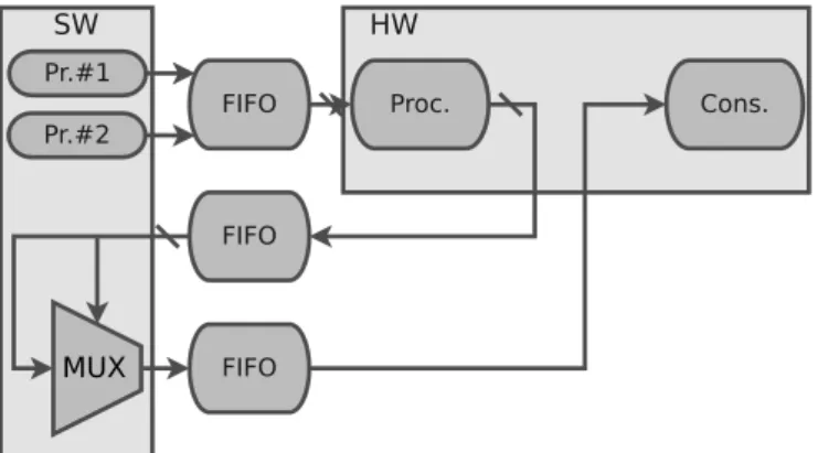
To outline the problem, we demonstrate a simple example in Figure 1 and 2, where two produc-ers from the software part transmits two bit streams to the hardware part through the double port First-In-First-Out (FIFO) buffer. On the hardware part, the received bit streams are processed and then passed to two input Multiplexer (MUX) with 1-bit address port. MUX multiplexes bit streams at the input to the consumer at the output.
Figure 1: MUX example before the execution context changing
Figure 2: MUX example after the execution context changing
If for some reason there is a need to reallocate the MUX from the HW to the SW side, then this process will require to make eight changes in the interfaces: Firstly, the MUX, which has 3 input and 1 output ports, should be excluded from the HW part, after that it is moved to SW part and new interfaces should be created. From the observed example it follows that in general for a component with a number of ports equals to n number of changes in interfaces is proportional to 2n. While the considered case is manually manageable, this problem becomes hard to solve when a number of replaced components reaches tens or hundreds of units.
2.5.
Vivado Design Suite HLx
Vivado Design Suite is a software tool produced by Xilinx as a successor of Xilinx Integrated Synthesis Environment (ISE). Xilinx ISE allowed developers to create FPGA based projects from HDLs sources to the final deployment. Vivado as a successor of Xilinx ISE is extended by additional functionality for high-level design approach:
• Software-defined Semiconductor intellectual property core (IP core) generation (HLS-C), • Block-based IP-integration (Vivado IP Integrator),
• Model-based design Integration (Model Composer, System Generator for DSP)
The IP core concept presents a way to describe a set of low-level components as one monolithic unit. For example, a DSP filter consists of a number of multipliers, delay lines and coefficients
representing its impulse response. When the filter is frequently used, such as a root-raised cosine filter in telecommunications, there is no need to implement this filter from scratch using HDLs for each new project. Instead of this more expediently to store this filter as a unit in a form of IP core for a future reuse. Also Vivado supports a workflow based on Block-designs cells (BD-cells). In a such workflow each component described by IP core may be easily integrated into a project using visual editor, which is also the part of Vivado Design Suite.
One of the great advantages of Vivado is that it has opportunities for integration with other tools such as Simulink to enable a MBD approach to development. In this workflow a developer may create and verify a design, using Simulink. Developed Simulink model can be packed in an IP core by the help of System Generator for DSP, but suitability of this approach at least for now is limited since the proposed technique is adequate and easy to use only for digital signal processing tasks, but for the other domains, such as control logic applications, it is quite challenging to create an appropriate model.
Moreover along with Vivado Design Suite Xilinx supplies its own Software Development Kit to support the software part of their SoC solutions.
2.6.
Visual System Integrator as a Solution for the Interfacing Problem
Visual System Integrator or simply VSI is a front-end for Vivado which offers a great solution to the interfacing problem. VSI splits the holistic view on a given system in two planes:
• System canvas is introduced for specification of a system’s functionality. The system canvas, in turn, is divided in Hardware and Software contexts. Blocks located in the Hardware context automatically ”compiles” into RTL description. Then the RTL description is mapped to the target FPGA resources, that results in a bitstream file for FPGA configuration. Design parts located in the SW context are compiled in a usual for embedded systems software way with a difference that interfacing provided in the corresponded sources are taken into account automatically.
• Platform canvas is introduced for configuring a target system. The platform canvas presents a processing system along with a some additional hardware support if it is needed.
VSI provides its own compiler to resolve relations between the System and Platform canvases. In general, the developer needs only to provide an appropriate set up for using a platform in the Platform canvas, and after that every change in the system described in System canvas will not affect any parts of the Platform canvas, even if the provided partitioning for a system in the System canvas has been changed.
In the system canvas, different blocks may be literally dragged and dropped from one context to another. VSI resolves all of the changes related with interfaces automatically. Moreover, in this case there would be no need to change functionality of each module provided in the related sources if they were described in High-Level Synthesis languages or, to be more concrete, HLS-C language.
2.7.
High-level Synthesis Languages
High-Level Synthesis languages most frequently referred to C-based synthesis is a technique based on autonomous translation of a C-based description into digital hardware. Through the use of Vivado and VSI along with HLS-C support, the desired system independence in terms of the execution context is achievable since a provided HLS-C description may be compiled on software side as well as implemented into hardware description (RTL) on hardware side.
Detailed description of the Xilinx’s HLS may be found in corresponded documentation (see [29]). VSI extends Xilinx’s HLS in order to cope with interfacing problem by introducing a set of new classes, most important of which are:
• hls::stream, • hls::stream_buffer,
because these classes implements a data exchange process between HW and SW parts. Detailed description of VSI’s classes may found in [30].
HLS accelerates the design flow and gives a new opportunity for software developers in a field of hardware design. However, if a high performance is required, HLS-C driven development is hardly an acceptable solution. For example an RTL description for hardware part is generated automatically during HLS process, and it is not guaranteed that generator will find the optimal solution according to the given criteria, because for most cases it produces sub-optimal solutions which is caused by the nature of algorithms used in this type of tools. Moreover, by default, without any additional preprocessor’s directives (such as #pragma HLS PIPELINE) generator has no information about desired hardware architecture. Also, from developer point of view, it is hard to predict how exactly a given line of an HLS-C source will be translated in hardware description. Below in the Listing 1 we give an example of one of the HLS-C sources from our use case project. In Listing 1 the functionality of the multiplier is implemented as a usual function (multiplier) written in C. However additional function (multiplier_stream) should be defined to specify how exactly the data should be read at the input and how it should be written to the output.
void m u l t i p l i e r ( uint21 ∗SPEED_IN, uint21 ∗SCALE_FACTOR, uint21 ∗MULT_OUT){ ∗MULT_OUT = ∗SPEED_IN ∗ ∗SCALE_FACTOR; }
/∗ t h i s f u n c t i o n w i l l be executed everytime
any data a r r i v e s on e i t h e r HALL_0 or HALL_1 or HALL_2 ∗/ void multiplier_stream ( h l s : : stream<uint21> &SPEED_IN,
h l s : : stream<uint21> &SCALE_FACTOR, h l s : : stream<uint21> &MULT_OUT){ s t a t i c uint21 speed_in ; s t a t i c uint21 s c a l e _ f a c t o r ; s t a t i c uint21 mult_out ; i f ( !SPEED_IN. empty ( ) )
speed_in = SPEED_IN. read ( ) ; i f ( !SCALE_FACTOR. empty ( ) )
s c a l e _ f a c t o r = SCALE_FACTOR. read ( ) ;
m u l t i p l i e r (&speed_in , &s c a l e _ f a c t o r , &mult_out ) ; MULT_OUT. w r i t e ( mult_out ) ;
}
Listing 1: HLS-C example
2.8.
Tcl as a Language Between Developer and Tools
The Tool Command Language [31] (Tcl) is a high-level programming language. Tcl is an interpreted language and programs written in Tcl are called scripts. In this study Tcl is considered as a command language between tools and developer. By its nature Tcl is a general purpose language, but it is widely used in embedded systems development for automation, Graphical User Interfaces, rapid prototyping and so on. Tcl shell is integrated in the mentioned tools: Vivado Design Suite and VSI.
Xilinx’s Vivado Design Suite Tcl Command Reference Guide [32] says that
Tcl is a standard language in the semiconductor industry for application programming interfaces, and is used by Synopsys® Design Constraints (SDC)
For our purposes need to be mentioned that most of commands executed in VSI or Vivado through a GUI may executed by Tcl commands. For example adding a new block in a BD, integrating IP-core in an existing system, interface creation, execution contexts (from HW to SW or vice versa) changing – all of this processes may be executed by Tcl scripts, which opens great opportunities for design-flow automation.
Vivado Design Suite extends a set of basic Tcl commands to provide an additional support for a developer. For the detailed description of Vivado’s Tcl commands see [32]. In turn VSI extends
the set of Vivado’s Tcl commands in order to support additional specific features. Some of the used commands are listed in the Table 5.
Both of the tools, VSI and Vivado, are Tcl driven. As we said, it provides opportunities for design-flow automation. From this perspective the main difference between two tools is that VSI is capable to solve an interfacing problem automatically and there is no need to modify each of the changed port manually.
2.9.
From Dependencies Description to Boolean Expressions
A special place in the variability problem is occupied by the issue of resolving dependencies. In this subsection we will briefly describe the formal mathematical approaches which may be useful in a context of this study. More detailed justification and description of the chosen method is given in the following sections.
We assume that any complex dependency is factorized on a set of simple rules. Linguistically, any rule can be formulated according to the following pattern:
Rule :
I f Condition then Expression
Listing 2: ”If-then” pattern for a simple rule
Leaving the structure of the pattern the same, we look at the ”if-else” expression from a slightly different angle, namely:
Rule :
I f Statement#1 then Statement#2
Listing 3: Modified ”if-then” pattern for a simple rule
Such a record implies that the formulated rule should be executed if the first expression is true and if the second one is true. We can also conclude that if the first expression is false, the second one can take any value. This fact is briefly expressed by the operation of implication in Boolean algebra:
S1⇒S2.
The use of such ”simple” rules is, in principle, sufficient to describe any factoring dependence. In practice, however, it may be appropriate to expand this approach by introducing a rule with an alternative choice, i.e. one that can be formulated linguistically according to a pattern:
Rule :
I f Statement#1 then Statement#2 Else
Statement#3
Listing 4: ”If-else” pattern for a rule with an alternative choice
In Boolean algebra, such a rule is known as a conditional disjunction, which represents a ternary operation, i.e. an operation on three operands. The conditional disjunction was introduced by Alonzo Church [33] and it may be written as follows:
[S1, S2, S3]↔ (S1→S2)∧ (¬S1→S3)
A rule with several alternatives can then be introduced, which is a composition of a simple rule and rules with an alternative and is formulated as the next pattern:
Rule :
I f Statement#1 then Statement#2
Else I f Statement#3 then Statement#4
. . . Else
Statement#N
A rule with multiple alternatives (Listing 5) may be rewritten as follows: Rule : I f Statement#1 then Statement#2 Else I f Statement#3 then Statement#4 Else . . . Else Statement#N
Listing 6: ”If-else-if-else” pattern for a rule with multiple alternative choices
Listing 6 highlights the fact, that in ”if-else-if-else” pattern consists of the nested ”if-else” patterns and it can be expressed in Boolean algebra operations in the following form:
[S1, S2,[S3, S4,[. . .[SN−2, SN−1, SN]. . .]]]↔ (S1→S2)∧
(¬S1→ ((S3→S4)∧ (¬S3→ (. . .(SN−2→SN−1)∧ (¬SN−2→SN). . .)))
This expression may be shortened using recursion. If we denote the conditional disjunction as
fn= [Sn, Sn+1, Sn+2], then the whole expression may be rewritten as follows:
fN−2= [SN−2, SN−1, SN]
fn = [Sn, Sn+1, fn+2],∀n=2k+1, k∈ [0, . . . ,(N−5)/2]
In general dependencies written as Boolean expressions form a Boolean equation system. More detailed description of Boolean equations along with techniques to solve such systems may be found in [34].
3.
Related Work
In software systems, variability management is usually achieved by Software Product Lines (SPL) approaches. Introduction to this field of study can be found in [35]. VPs in SPL are represented by the Feature-Oriented Domain Analysis (FODA) [36]. According to [7] SPL represents the variability in an architecture, while the FODA describes the variability in functionality. Moreover, there exists several formal languages for variability management and description. For example, Feature Models (FM) and Orthogonal Variability Model (OVM). Description and interoperability between these two formal frameworks may be found in [37], where authors described a way to transform FM description into OVM description. In this report, we present a description of the considered case study using these two formal approaches. The difference between FM and OVM is that the former takes into account variabilities and commonalities, while the later represents only VPs and variants.
From software variability, industry moved gradually towards system variability. The reason is that, with the development of the modern electronic devices, robotics, internet of things, sensor networks, software defined networks and so on, there is a need to support variability not for software artifacts only, but for components of the complex systems, as well. These components may be presented as hardware devices and even as the environmental objects as is the case with the robotics systems. These new challenges are considered by Gherardi during analyses of the possible variability in robotic systems [7]. The work proposes a new approach for modeling and resolving existing variabilities. The main advantage is that it proposes useful guidelines for software developers in this field, using real examples of sources written in modern high-level programming languages. Moreover, it proposes a set of recommendations and approaches for code refactoring in robotic systems. The gap of this research is that the thesis work provides practical solutions only for software developers in the robotics domain.
Most of the studies consider the system variability from software perspective, even if they pretend to describe something beyond software variability and SPL. An overview of the latest trends in software and systems variability may be found in [10]. As we can see from this study, different approaches related with self-adaptive and autonomous systems, real-time critical systems consider only variability at run-time. Also authors state, that:
…SPL practitioners should provide ways to manage large variability models, from ex-plicit representation of variants and VPs to configuration and implemntation issues, particularly for reconfiguring variants at any time.
Our study is aimed to provide a design flow, which takes into account realization issues since the proposed workflow is produced from the development process on the real project and would allow reconfigure variants at implementation time with a some degree of automation.
The variability problem from perspective of hardware and the relation of it to the software variability is considered in [8]. Here, authors develop a Hardware Variability Model (HVM) to describe variability in hardware. They also introduce a method for describing relations between the developed HVM and software, in order to handle possible dependencies between the two target platforms using hardware properties. However, the authors stated that hardware and software variabilities should be described separately from each other, even if complexity of development increases. In our report, we show how it is possible to avoid such separation using High-Level Synthesis languages (or to be more concrete HLS-C) for hardware and software development.
In a recent study, authors address a problem of variability of systems consisting of heterogeneous components [9]. They call these systems as Cyber-physical System (CPS). Authors argue that
…one reason for many challenges in CPS engineering is the variability and heterogene-ity in software and hardware as well as the variabilheterogene-ity in the environmental contexts, requirements, and application scenarios.
Moreover they have found that this challenging problem has not been addressed by existing studies in a holistic means. In the related study authors only ”sketched a vision” on a development approach to CPS with variability. Which means, that any practical and concrete recommendations to developers are not presented in the given study. We hope that our study will be a small step forward towards the solution of the described variability problem for CPS.
4.
Method
In general this study may be identified as a case study since it is conducted in the given company (ABB) on the given project. The proposed case study research process is shown in Figure 3. Partially it follows a case study research process described in [38]. Since we aim to provide a some degree of formalisation and generalisation it was decided to include some additional steps in the research process. Thus, in order to formalise and generalise some of the used concepts, the additional task T5 was added to the study design according to [39]. Also in this study an implementation of the described principles are presented as a Python-based tool. Because in this work we do not just observe the given object of study, but also try to improve existing processes and design flow, which is described by task T6, this study may referred to an action study, see for example [40].
Figure 3: Research process
We split the whole research process into seven tasks:
• T1: during this stage we define an object under research (which is in a narrow sense the given project, see detailed description in subsection 5.1.), formulate the research questions (see subsection 1.4.) and plan the case study.
• T2: preparation of data collection defines an approach to data collection, basically, pro-cedures and protocols. Briefly speaking it was decided to obtain a useful data (existing concepts, points for improvements, implementation related data – such as required actions, corresponded commands and approaches for automation of the proposed design flow) par-tially from studying state-of-the-art methods and techniques (section 1. and section 3.), partially from studying used tools and its capabilities and limitations. Finally some data should be extracted from the real workflow on the given project in a form of identified most repetitive actions and corresponded commands for automation, which is listed in Table 5. • T3: at this stage the data collecting is executed.
• T4: collected data is analysed. In the context of this study it means an application of existing approaches to the given project in order to estimate its suitability and identify the existing drawbacks. This part is mostly related with subsections 5.2. and 5.3.. Also a comparison with another possible solutions and tools are discussed in section 6.. Required functionality,
which should be provided by the proposed design flow and was obtained during data collection process, is discussed in subsection 5.5..
• T5: attempt of a some degree of formalisation of the useful concepts, produced as a result of a previous data analysis, is presented in section 5.4. (T5.1). General concept of the proposed design flow is given in subsection 5.6. (T5.2).
• T6: Implementation related issues are discussed in subsection 5.7.. We assume that imple-mentation process my adjust the formulated principles and concepts.
5.
Process of Design Flow Creation
5.1.
Description of the Example Project
The given use case is a BLDC Motor. We will not go into the details of the implementation of such projects, as in general it does not matter for the task at hand. From the point of view of the problem to be solved, it is reasonable to describe the project structure. In other words we need to produce what is called Data Flow Graph (DFG). The DFG for the given project is presented on Figure 4 a).
Note that the Data Flow Graph represents the original version of the project, without optional blocks or, in other words, possible variants are not included into this version.
It is known that it is needed to add the feature safety to the project. It is also known that two variation points are related to the feature: Safety Torque Off (STO) and Safety Limited Speed (SLS). Moreover, we assume that for all Blocks, the functions written in HLS-C are defined and described corresponding to them.
Prototyping and modeling were performed in Simulink software environment. With the help of code generation tools, software artefacts were obtained, which, in their turn, were partially modified manually. The issues of modeling and prototyping, as well as generation of software artefacts are not considered in this work, as well as the issues of identification and analysis of possible features and corresponding variation points.
The starting point for the described design flow is the presence of source files written in HLS-C, as well as the definition of relationships between Blocks and dependencies for VPs. All of the project blocks are listed in Table 2. As we said, we need to add the feature – safety to the project and it is also known how exactly each block, which is a variation point, should be included to the described DFG. In general, this is shown in Figure 4 b) and a more detailed description of the relationship between ports is given in Table 3 and Table 4.
Number Block name Type
0 GLITCH_FILTER Mandatory Block 1 STARTUP Mandatory Block 2 SPEED_CALC Mandatory Block 3 SLS_PROTECTION Optional Block (variant) 4 PICONTROLLER Mandatory Block 5 PWM_GENERATOR Mandatory Block 6 PHASE_FSM Mandatory Block 7 DISTRIBUTOR Mandatory Block 8 PHASE_DECODER Mandatory Block 9 STO_PROTECTION Optional Block (variant)
Table 2: Example project’s blocks
Regarding Table 2 pay attention to the fact that the variants (STO and SLS) are still considered as blocks. There is no difference between a variant and a block except for that one property of these blocks are different (here we denote this property as a type - mandatory or optional). A mandatory block must be included in the project, but for an optional block it is not necessary.
From Figure 4, where DFGs are shown, it is possible to extract a useful information about changes in interfaces related to exclusion or inclusion the variants. These extracted information is shown in Table 3 for STO variant and in Table 4 for SLS variant.
5.2.
FM and OVM Descriptions
In this subsection, we describe the project using special visualization languages, exploiting two practices: FM and OVM. FM and OVM were created to visualize projects containing variability. It is assumed that these methods can be used not only to visualize, but also to keep track of existing variation points, variants and dependencies between different entities.
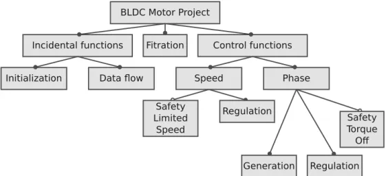
In Figure 5, the FM model for the project is presented. We defined several features as well as their type – mandatory or optional. As we can see from the FM model, feature Speed contains an
a) DFG of the project without any variants b) DFG with SLS and STO variants
Figure 4: DFGs of the given project
STO_PROTECTION PHASE_DECODE DISTRIBUTOR PWM_A (input) PWM_A (output)
PWM_B (input) PWM_B (output) PWM_C (input) PWM_C (output) RST_A (input) RST_A (output) RST_B (input) RST_B (output) RST_C (input) RST_C (output)
STO_EN (input) OUT_D1 (output)
Table 3: Interconnection ports between STO and dependent mandatory blocks
optional feature – Safety Limited Speed (SLS). The same is concluded about the feature – Phase, containing an optional feature – Safety Torque Off (STO).
Figure 5: FM for the example project
Observing the FM model of the project, we can conclude that the most features of the project are mandatory features and their place in the project and relationships between them most prob-ably will not be changed or at least this part doesn’t require a lot of repetitive actions during implementation stage of the design flow. From this point of view, it is more reasonable to use OVM, because OVM takes into account only variation points. OVM-based description of the given project is shown in 6.
5.3. Drawbacks with FM and OVM Descriptions
In the previous subsection describing the project using FM and OVM we have not introduced any dependencies between features. The reason is that on the given abstraction level — feature
descrip-SLS_PROTECTION PI_CONTROLLER SPEED_REF_OUT (output) SPEED_REQ (input)
Table 4: Interconnection ports between SLS and bounded mandatory blocks
Figure 6: OVM for the example project
tion — those dependencies are hidden. Still, there is a need to describe and manage dependencies, as well as the whole project structure. From developer’s point of view, a block is a notion more useful and relevant than a feature. Because a developer works with blocks. Dependencies should be introduced between blocks to support developer. For example the same OVM model may be applied, but it should be detailed with an inclusion of the low level blocks. For example in Figure 6 we introduced a variation point called SPEED and bounded variant to the point - SLS. From this view we do not know how exactly the Safety is implemented. To support a developer, we need to deepen this description, describing the project structure using blocks but not the corresponded features.
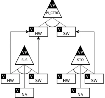
Figure 7: OVM with dependencies for the example project
In Figure 7, we show the detailed description, where the SLS is considered as a variation point, while in the original description on Figure 6 the SLS is treated as a variant. The reason is in the example project for all blocks we have a variability related with the execution contexts, because each block may be implemented either on SW or HW side. Including blocks in the OVM description makes it possible to introduce dependencies between these blocks related with the execution context in comparison with the Figure 6.
For the purpose of demonstration, we introduce the next dependencies:
I f STO i s executed i n SW then
I f SLS i s i n cl u de d i n t o the p r o j e c t then PI_CONTROLLER should be executed i n HW
Listing 7: Dependencies example
However, when we introduce such dependencies, we need to take into account that in this case each mandatory feature becomes a variation point and hence there is no difference between OVM and FM descriptions. Moreover if the number of dependencies increases, then the complexity of OVM and FM descriptions rises proportionally. Moreover FM and OVM does not provide any methods to resolve dependencies by default, which may be critically important when number of dependencies rises. Moreover it is not obvious how to process by computer these OVM and FM models to support changes between the project and the given models automatically.
For these reasons in the next section, we make an attempt to redefine and formalize some of the used terms and concepts.
5.4.
Formalisation of the Used Concepts
In this subsection we make an attempt to give a strict definition to such concepts as Block, Variant, Function. To illustrate these terms we refer to the Data Flow Graph concept introduced before.
A Block represents a node of the Data Flow Graph. In general a block is characterized by its inputs and outputs. A Block is similar to the entity or module concepts used in HDL languages such as VHDL or Verilog. A Block contains information about types of the inputs and outputs, but it doesn’t contain any information about its internal functionality. We denote an instance of a Block as b and a set of blocks as B, thus b∈B.
A Function represents the internal content of a Block. We assume that each Function is described by a text artifact, in our case a file containing source code. In the considered case, a Function is literally a HLS-C function, such as the multiplier_stream function given in Listing 1.
We denote a Function as f and a set of Functions as F. Moreover we denote a software artifact as SA. Since a Function is contained in a software artifact, we may write f ∈SA, in turn a set of
software artifacts should be a partition of F, where partition is considered in a strict mathematical sense. Moreover we imply that a bound between Functions and Blocks exists and known. We denote these correspondences from a set of Functions to a set of Blocks as m(): F→B.
Using the definitions formulated above it is possible to give a formal definition to Variant. We denote Variant as v and a set of Variants as V. We say that the given Block b is a variation point if:
∃{f1, . . . fn} ∈F |m(f1) =b ∧ · · · ∧m(fn) =b, n∈N, n>1
In a similar way, we may define a Variant. We say that a given function f ∈F is a Variant if:
∃{f1, . . . fn} ∈F| m(f) =b∧ m(f1) =b ∧ · · · ∧ m(fn) =b, n∈N, n≥1
From the mathematical perspective, the procedure m()may be considered, in a common case, as a surjective function. If a set of Variants is an empty set V={∅}, then m()becomes a bijective function. The described definitions and properties may be helpful in an error checking process. For example, if a set of Variants V is not an empty set, then surjection of m()should be met, otherwise a given project contains errors, for example insufficient number of Functions or redundant number of Blocks. Definition of the VP gives an opportunity to extract Variants from SAs and map them to Blocks.
We consider a Block as a dominant concept. Functions, Variants, execution contexts are con-sidered as attributes of a Block. Moreover dependencies, Blocks whose parameters should be changed if a parameter of a given Block was changed, also are treated as attributes. We denote this attributes as BLOCK_NAME.attribute.
We propose to formulate dependencies in a from of rules under assumption that each compli-cated dependency may be factorized to simple rules, which can be formulated in a form of ”if-else” statements. Thus if R is a decomposable dependency, then it may be represented as decomposition on simple rules: R=r1∧r2∧ · · · ∧rn. As an example of this and to show it’s usefulness, we refer
First, we extract the Boolean expressions from the given rules. If the attributes of the STO_PROTECTION Block have been changed, the Block can be considered as a valid Block only if the next statement is True:
(SLS_PROTECTION.status==′Included′)⇒ (PI_CONTROLLER.context==′HW′), or in a short form:
a→b.
Since SLS_PROTECTION depends on PI_CONTROLLER and STO_PROTECTION also depends on PI_CONTROLLER than rules formulated for STO_PROTECTION also should be checked. Thus the next statement has
to be True:
(STO_PROTECTION.contexts==′SW′)⇒ (PI_CONTROLLER.context==′SW′). or in a short form:
c→d.
These two statements must be executed together. This fact is written in the following form:
(a→b)∧ (c→d) =True.
Solutions of the given Boolean equation contain all of the possible configurations for the given Blocks, their dependencies and the chosen attributes.
5.5.
Identification of the Required Functionality
In this subsection, we identify the required functionality. This functionality has been extracted from the work process on the example project. As we said we assume that variation points have been identified. Variants for each VP have been identified as well. Also, we assume that HLS-C sources, which are called as software artifacts, exist.
At the first stage we defined a configuration of used platform. This configuration is provided in Platform Canvas of VSI. This process is out of scope of the proposed design flow, since it doesn’t take a lot of repetitive actions from developer in a sense that for the given project platform configuration may be done once and for all.
At the second stage we create what is called Application System in VSI. Application System represents the given in Figure 4 a) Data Flow Graph. At this stage it does not matter in which execution context each block was placed. For the sake of certainty let’s say that all of the blocks initially were placed in SW execution context.
On the next step we added features in the project, which are presented by two blocks: STO and SLS. Thus we have created two versions of the project according to the Figure 4. If variability in the execution contexts and possible dependencies are not considered, then exists four versions of the project since the project contains only two optional blocks (STO and SLS), and the others are mandatory blocks.
Producing of another version which is between the mentioned versions requires the design flow capable to perform the next operations:
1. It should be possible to change the execution context of using blocks. 2. It should be possible to include or exclude optional blocks.
3. It should be possible to resolve existing dependencies automatically.
All of the listed operations should be handled on a higher level of abstraction than it is provided by VSI. We suppose that it will support a developer activities, by eliminating the need to execute repetitive actions. Such repetitive actions have been observed in our use case example during manually producing different versions of the analyzed project.
Here, we make an attempt to give an estimation of developer’s efforts needed to produce these actions. As a metric of this, the number of mouse clicks was chosen. These simple actions are listed in the Table 5.
Action Number of actions Tcl command Moving a block between execution contexts 1 move_bd_cells
Adding a new block 5 create_bd_cell Adding a port 3 create_bd_intf_port
Adding a pin 3 create_bd_intf_pin Adding a net 1 create_bd_intf_net Deleting an object 1 delete_bd_objs
Table 5: Repetitive actions and efforts evaluation
For example adding the STO variant in the project would require to execute approximately 60 mouse-clicks. Considering the GUI delay and human delay the action can take about five minutes of a developer’s time, while not taking into account a dependency resolving process and other side effects. In Table 5 we listed the Tcl commands useful for executing the listed actions. Since Tcl commands and actions are known, the process may be automated.
5.6.
General Concept
In this section, we introduce a general concept of the proposed design flow. The schematic descrip-tion is shown in Figure 8.
Figure 8: The general concept of the design flow
We assume that the Software Artifact (SAs) and the data flow graph are known. We consider the use of VSI, because it allows achieving a desired technology independence with a minimal effort. The initial version, which acts as a modifiable basis, should be produced by developer manually. When this is done, the future generation of possible versions is put on a higher level of abstraction by the developed tool, implementing the proposed approach.
The developer should provide the necessary information about a desired version by the user interface (UI), the description of rules for dependencies (R) and the variation points (which Block is a variant and which one is not). During an extraction process (implemented by the Extractor module in Figure 8), the input information about desired attributes, dependencies and variants is processed and after the extraction, the Blocks should be represented as objects containing attributes defined by the user input.
The Solver module processes the objects of Blocks, their attributes and dependencies in order to find possible conflicts. If the set of objects is conflict-free, then the objects, representing the project blocks, may be translated into description processable by VSI. The Dictionary in Figure 8 defines a correspondence between required actions and VSI commands.
5.7. Example of the Implemented Tool
As the programming language for implementation, we use Python, since it allows to create a working prototype in a short time frame. As the language between the implemented tool and VSI