Energy Procedia 00 (2016) 000–000
www.elsevier.com/locate/procedia
The 8
thInternational Conference on Applied Energy – ICAE2016
Property Impacts on Plate-fin Multi-stream Heat Exchanger
(Cold Box) Design in CO
2
Cryogenic Process: Part I. Heat
Exchanger Modeling and Sensitivity Study
Yuting Tan
a,*, Worrada Nookuea
b, Hailong Li
b, Eva Thorin
b, Jinyue Yan
a,b,† aSchool of Chemical Science and Engineering, Royal Institute of Technology, SE 100 44 Stockholm, SwedenbSchool of Business, Society and Engineering, Mälardalen University, SE 721 23 Västerås, Sweden
Abstract
The multi-stream plate-fin heat exchanger is one of the most important components in the CO2 cryogenic system. Appropriate design methodology and in-depth analysis of property on the heat exchanger are of importance. This paper, as part I of the two-paper series, presented the design procedure for the multi-stream plate-fin heat exchanger in CO2 cryogenic process. Sensitivity study was also conducted to analyze the impacts of thermos-physical properties including density, viscosity, heat capacity and thermal conductivity. The results show that thermal conductivity has the most significant impact and it should be prioritized to develop a more accurate thermal conductivity model for the heat exchanger design. In addition, viscosity has least significant impact but the higher uncertainty range of viscosity may lead to a higher possible deviation in volume design.
© 2016 The Authors. Published by Elsevier Ltd.
Selection and/or peer-review under responsibility of ICAE
Keywords: Thermo-physical property, CO2 mixture, heat exchanger, CO2 cryogenic, sensitivity study
Nomenclature
Symbols nW Total width (m)
A Surface area of passage per unit width per unit length (m2/m2)
P Pressure (Pa)
a Constant in equation (3) Pr Prandtl number of stream
* Corresponding authors. Tel.: +46-(0)8-790-6223
E-mail address: tany@kth.se
† Corresponding authors. Tel.: +46-(0)8-790-6528
Ac Cross-sectional area of passage per unit width (m2)
Q Heat load (kW)
b Constant in equation (3) rh Hydraulic radius of fin (m)
c Constant in equation (3) Re Reynolds number
Cp Heat capacity of stream (kJ/kg∙K) Ts Surface temperature of wall (K)
d Constant in equation (3) T Temperature (K)
f Fanning friction factor W Width of finned plate (m)
h Heat transfer coefficient (W/m2∙K) ∆H Enthalpy change of stream (kJ/kg)
j Colburn factor ∆P Pressure drop of stream (Pa)
k Thermal conductivity (W/m∙K) Greek symbols
L Length of heat exchanger (m) Viscosity of stream (Pa∙s)
m Mass flow of stream (kg/s) Density of stream (kg/m3)
n Number of flow passages Overall surface efficiency
1. Introduction
Carbon Capture and Storage (CCS) accounts for a potential reduction of 14% of greenhouse gases emissions in achieving 2°C climate change target by 2050 [1]. Oxy-fuel combustion is one of the most promising technologies for CO2 capture [2]. There are mainly two types of cryogenic processes for CO2 liquefaction and purification in oxy-fuel combustion, namely flash process and distillation process. For flash process, Fig. 1 (a) represents the flow sheet of a typical two-stage flash process for CO2 purification. After compression and cooling process, the water in flue gas generated from oxy-fuel combustion boiler is removed by separator drum and adsorption column, then the flue gas is sent to the multi-stream heat exchanger for condensation. The volatile gases are then removed by flash tanks and the purified CO2 stream is pumped for transportation [4].
The plate-fin multi-stream heat exchanger is considered as one of the most important components. Fig. 1(b) shows the schematic of a plate-fin multi-stream heat exchanger. Many studies have been done on the design and optimization of the plate-fin multi-stream heat exchangers used in industrial processes, such as air separation unit and district heating process [6-8]. However, for the CO2 purification process, the previous studies only focused on thermodynamic feasibility of the heat exchanger from the perspective of process simulation without considering the actual sizing design. Therefore further work should be done in the sizing design procedure of multi-stream heat exchanger in CO2 cryogenic processes.
(a) (b)
Fig. 1 (a) Flow diagram of two-stage flash process for CO2 cryogenic (Adapted from [2, 3]); (b) Schematic drawing of plate-fin multi-stream heat exchanger (Adapted from [5])
Different properties of working fluids, including density, viscosity, heat capacity and thermal conductivity [9-10], are inherently linked to design parameters. Under- or over-estimated properties may result in a high investment cost or the failure of operation. Therefore before the gaps in experimental data
and property models have been fulfilled [11], the property impacts need to be investigated in order to identify the most important properties which need to be prioritized for property model improvement. After that, the model evaluation needs to be done to give recommendations for property model selection for current use.
In this paper, as part I of the two-paper series, the detailed design of a plate-fin multi-stream heat exchanger for CO2 cryogenic process was performed. Based on the design model, a sensitivity study was conducted in order to identify the impacts of properties on technical design, in order to further identify the key properties and the priority for the property model development. In part II of the two-paper series, the models of the identified properties are evaluated and recommendations are given for property model selection.
2. Design Method of plate-fin multi-stream heat exchanger 2.1. Input parameters and assumptions
The details of streams (including temperature, pressure, composition, and mass flow rate) in two heat exchangers (HE1 and HE2) are listed in Table 1 for a conceptual 600 MWe oxy-fuel combustion pulverized-coal-fired power plant [3]. The streams can be classified as hot streams (H1, H2) and cold streams (C1-C4). For example, the hot stream in HE1 is defined as H1, and the inlet and outlet parameters represented by S2 and S3 in Fig. 1 (a) respectively.
Table 1. Parameters of streams in multi-stream heat exchangers [3]
Stream T (oC) P (bar) m (kg/s) CO
2/O2/N2/Ar (mol %)
HE1 Inlet Outlet Inlet Outlet
H1 35.00 -24.51 30.00 29.72 717.2 82.40/4.19/ 9.51/ 3.90 C1 -43.15 23.40 29.17 28.9 118.5 24.29/17.51/41.64/16.56 C2 -43.15 23.40 8.54 8.33 186.0 95.60/1.26/2.08/1.06 C3 -31.12 23.40 18.80 18.59 412.6 97.50/0.69/ 1.21/ 0.60 HE2 H2 -24.51 -54.69 29.72 29.45 304.5 63.89/8.49/19.66/7.96 C1 -54.69 -43.15 29.45 29.17 118.5 24.29/17.51/41.64/16.56 C2 -55.06 -43.15 8.74 8.54 186.0 95.60/1.26/2.08/1.06 C4 -54.69 -43.15 29.45 29.24 186.0 95.60/ 12.6/2.08/1.06
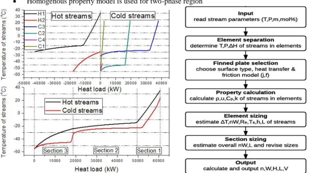
Based on the input parameters, Fig. 2 (a) shows the T-Q diagram and composite curves of main streams in the multi-stream heat exchanger. In T-Q diagram, as stated above, the heat exchangers consist of two hot streams (H1, H2) and four cold streams (C1-C4), covering liquid, vapor and two-phase regions. As shown in the figure, the heat loads for hot streams are set negative while the heat loads for cold streams are positive. The composite curves consist of two separate lines, and each line consists of a series of lines representing different streams in different phase regions, therefore Wang et al. divided the multi-stream heat exchanger into different sections according to the composite curves [12]. In this study the heat transfer process in the multi-stream heat exchanger can be divided into three sections, as shown in Table 2 and Fig. 2 (a). The sections 1, 2 and 3 are further divided into 13, 30 and 17 elements, respectively. Each element has a heat load of around 1000 kW.
Table 2. Sections in multi-stream heat exchanger
Section Streams Region No. of elements
1 H1, C1, C2, C3 Vapor phase 13
2 H1, C1, C2, C3 Vapor, liquid, two-phase 30
3 H2, C1, C2, C4 Vapor, liquid, two-phase 17
Based on the above analysis, the following assumptions were made for the design process: The heat loss is ignored
Homogenous property model is used for two-phase region
Fig. 2 (a) T-Q diagram (up) and composite curve (down) of streams in multi-stream heat exchanger; (b) Flow chart of design procedure and programing
2.2. Design model
For single element design, Prasad [13] provided a straightforward method which is applied in this study. A brief introduction of the method is presented as below and more details can be referred to the previous studies [12-13].
For the plate-fin heat exchanger, it is necessary to know the heat transfer and flow friction characteristics of the enhanced surfaces, mainly the Colburn factor j and Fanning friction factor f. Offset strip fins were used in this work and the correlation developed by Bhovmik and Lee [14] is
(1)
(2) The total width of the element can be estimated by
(3) where , , , , represent viscosity, heat capacity, density, mass flow rate and Prandtl number of the stream. and are enthalpy change and pressure drop of the stream. , , are cross-sectional area of passage per unit width, overall surface efficiency and hydraulic radius of fin. is temperature difference between hot and cold streams.
The length of element can be obtained from the equation below,
(4) where is the heat transfer coefficient and is surface temperature of the element. is the surface area of passage per unit width per unit length. The heat transfer coefficient can be calculated from the equation below,
So far the element design has been established. Following the method, for each stream, the size of all involved elements can be estimated. Then the overall length and overall width of the section for each stream can also be estimated as [15]
(6)
(7) For each stream, the calculated section size may be different. The smallest of the section lengths is taken as the section length, because it cannot be increased without violating the pressure drop constraint. Afterwards, the length of other streams is adjusted to this value. Thus if the stream has the smallest flow length, the width of section for other streams can be adjusted as
(8) Once the finned plate is determined, the number of flow passages for each stream can be decided by the following equation since the total width is already known,
(9) where W is the width of finned plate, the strip finned plate with surface type 1/8 – 15.2 is chosen in this study. The total height then can be decided by following equation
(10) where is the height of the fin channel.
Based on the design model, a computer program was developed in Matlab. Fig. 2 (b) shows the flow chart for plate-fin multi-stream heat exchanger design.
2.3. Property calculation
The homogenous two phase flow model was used in this work. In this model, the vapor and liquid phases were assumed to be in thermal equilibrium, well-mixed and flowing through the exchanger at the same velocities. The homogenous properties were estimated from the following equations [16-18]:
(11)
(12) (13) (14) (15) where is Lockhart-Martinelly parameter, is vapor quality and is enthalpy of streams. Subscript and represent liquid and vapor phase, respectively. The properties (including density, heat capacity, viscosity and thermal conductivity) for this study were obtained from a property database Reference Fluid Thermodynamic and Transport Properties (REFPROP) [19].
3. Results and discussion
3.1. Design results of multi-stream heat exchanger
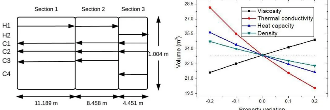
Following the design procedure, the detailed design parameters can be calculated accordingly. Table 3 lists the sizing parameters of three sections in multi-stream heat exchanger and Fig. 3 (a) shows the sketch of the heat exchanger network. After the initial design and parameter adjustment, the heat exchanger’s
height, length and width are 1.004 m, 24.098 m and 1.002 m respectively for the multi-stream heat exchanger used in a conceptual 600 MWe oxy-combustion pulverized-coal-fired power plant.
Table 3. Sizing parameters of different sections
Section Height (m) Length (m) Width (m) Volume (m3) Passage no.
1 0.948 11.189 1.002 10.634 90
2 1.004 8.458 1.002 8.508 96
3 0.948 4.451 1.002 4.228 90
Total 1.004 24.098 1.002 23.370 96
3.2. Uncertainties of the models for properties
The accuracies of calculated thermo-physical properties vary with the properties and the models used. The collected uncertainty ranges of property models are listed in Table 4. The uncertainty ranges of the properties can be up to ±12.8%, for example, the uncertainty range of density. Therefore, in the sensitivity studies, the evaluated deviation range was set at ±20%, in order to identify the property impacts within the possible deviation range of the property models.
Table 4. Uncertainty ranges of different property models of CO2 mixtures
Property Mixtures Uncertainty range % Source
Density CO2/N2 ±12.8 [20] [21] [22]
Heat capacity CO2/CH4, CO2/C2H6 ±5.0 [23] [24]
Viscosity CO2/N2 ±8.0 [11] [25]
Thermal conductivity CO2/N2 ±10.0 [11] [26]
3.3. Impacts of properties on multi-stream heat exchanger design
According to the model of multi-stream heat exchanger, the size of heat exchanger is related to viscosity, thermal conductivity, heat capacity and density. Fig. 3 (b) shows the deviation in volume of heat exchanger when properties vary in a range of ±20%, and the impacts of different properties on the heat exchanger volume designs are different. It is clear that the overestimations of thermal conductivity, heat capacity and density lead to underestimation of the volume of heat exchanger; whereas the overestimation of viscosity leads to the overestimation of heat exchanger volume. The increase of viscosity, on one hand, leads to decrease in heat transfer coefficient, which results in increase in volume of heat exchanger; on the other hand, leads to increase in pressure drop, therefore volume increases in order to meet the requirement of pressure drop constraints. When thermal conductivity, density and heat capacity increase, the heat transfer increases accordingly, therefore a smaller volume of the heat exchanger is needed.
Fig. 3 (a) Sketch of the design of heat exchanger network; (b) Sensitivity study results of property impacts on volume of heat exchanger
The heat exchanger volume is most sensitive to the deviation of thermal conductivity. Overestimating and underestimating the thermal conductivity by 10% change the volume from 23.4 m3 to 21.6 m3 and 25.5 m3, respectively, which correspond to the variations of -7.7% and 9.2%, respectively. For heat
capacity, +10% and -10% deviations of the heat capacity change the volume from 23.4 m3 to 22.5 m3 and 24.4 m3, respectively, which correspond to the variations of -3.9% and 4.5%, respectively. For viscosity, overestimation and underestimation of viscosity by 10% change the volume from 23.4 m3 to 24.2 m3 and 22.5 m3, respectively, which correspond to the variations of 3.4% and -3.6%, respectively. The heat exchanger volume is least sensitive to the deviation of density. +10% and -10% deviations of the density change the volume from 23.4 m3 to 22.8 m3 and 24.0 m3, respectively, which correspond to the variations of -2.4% and 2.7%, respectively.
4. Conclusion
The design procedure for plate-fin multi-stream heat exchanger in CO2 cryogenic process was proposed in this paper, and design results were presented for the multi-stream heat exchanger in a conceptual 600 MWe oxy-combustion pulverized-coal-fired power plant. A sensitivity study was conducted to investigate the property impacts on the sizing design of plate-fin multi-stream heat exchanger. The following conclusions can be drawn:
Among the investigated properties, the thermal conductivity has the most significant impact on the multi-stream plate-fin heat exchanger volume design. Therefore, developing a more accurate thermal conductivity model should be prioritized for the application of heat exchanger design.
Viscosity was found to have less significant impact than the heat capacity. However, the higher uncertainty range of viscosity, compared to the uncertainty range of the heat capacity, may lead to a higher possible deviation in the volume of the heat exchanger.
Acknowledgements
The financial support by Swedish Energy Agency and Swedish Research Council is appreciated. Yuting Tan appreciates scholarship from China Scholarship Council (CSC). Worrada Nookuea would like to appreciate the foundation of tandläkare Gustav Dahls memory.
References
[1] IEA. Energy Technology Perspectives. 2014.
[2] Y. Hu, H. Li, J. Yan. Integration of evaporative gas turbine with oxy-fuel combustion for carbon dioxide capture. International Journal of Green Energy. 7 (2010), 615-631.
[3] B. Jin, H. Zhao, C. Zheng. Optimization and control for CO2 compression and purification unit in oxy-combustion power plants. Energy. 83 (2015), 416-430.
[4] A. Aspelund, K. Jordal. Gas conditioning—The interface between CO2 capture and transport. International Journal of Greenhouse Gas Control. 1 (2007), 343-354.
[5] M. Picón-Núñez, G.T. Polley, M. Medina-Flores. Thermal design of multi-stream heat exchangers. Applied Thermal Engineering. 22 (2002), 1643-1660.
[6] H. Chang, K. H. Gwak, S. Jung, H. S. Yang, S. Hwang. Plate-fin heat-exchangers for a 10 kW Brayton cryocooler and a 1 km HTS cable. Physics Procedia. 67 (2015), 221-226.
[7] L. Wang, B. Sundén. Design methodology for multi-stream plate-fin heat exchangers in heat exchanger networks. Heat Transfer Engineering. 22 (2001), 3-11.
[8] R. Boehme, J. A. R. Parise, R. P. Marques. Simulation of multistream plate-fin heat exchangers of an air separation unit. Cryogenics. 43 (2003), 325-334
[9] T. Küster, R. Eggers. Liquefaction of oxyfuel flue gases – experimental results and modeling of heat transfer coefficients for pure CO2. Energy Procedia. 51 (2014), 109-118.
[10] B.S.V. Prasad, S.M.K.A. Gurukul. Differential methods for the performance prediction of multistream plate-fin heat exchangers. Journal of Heat Transfer. 114 (1992) 41-49.
[11] H. Li, Ø. Wilhelmsen, Y. Lv, W. Wang, J. Yan. Viscosities, thermal conductivities and diffusion coefficients of CO2 mixtures: review of experimental data and theoretical models. International Journal of Greenhouse Gas Control. 5 (2011), 1119-1139.
[12] L. Wang, B. Sundén. Design methodology for multi-stream plate-fin heat exchangers in heat exchanger networks. Heat Transfer Engineering. 22 (2001), 3-11.
[13] B. S. V. Prasad. The sizing and passage arrangement of multi-stream plate-fin heat exchangers. Heat Transfer Engineering. 17 (1996), 35-43.
[14] H. Bhowmik, K.S. Lee. Analysis of heat transfer and pressure drop characteristics in an offset strip fin heat exchanger. International Communications in Heat and Mass Transfer. 36 (2009), 259-263.
[15] B. S. V Prasad. Differential method for sizing multi-stream plate fin heat exchangers. Cryogenics. 27(1987), 257-262. [16] S. Levy. Two phase flow in complex systems. John Wiley & Sons Inc., Canada. 1999.
[17] A. Abdul-Razzak, M. Shoukri, J.S Chang. Characteristics of refrigerant R134a liquid-vapor two-phase flow in horizontal pipe. ASHRAE Transaction Symposium. 101 (1995), 953-964.
[18] R.W. Lockhart, R.C. Martinelli. Proposed correlations of data for isothermal two-phase, two-component flow in pipes. Chemical Engeering Progress. 45 (1949), 39-48.
[19] E.W. Lemmon, M.L. Huber, M.O. Mclinden. NIST reference fluid thermodynamic and transport properties—REFPROP user’s guide. 2013.
[20] H. Li, J. P. Jakobsen, Ø. Wilhelmsen, J. Yan. PVTxy properties of CO2 mixtures relevant for CO2 capture, transport and storage: review of available experimental data and theoretical models. Applied Energy. 88 (2011), 3567-3579.
[21] H. Li, J. Yan. Impacts of equations of state (EOS) and impurities on the volume calculation of CO2 mixtures in the applications of CO2 capture and storage (CCS) processes. Applied Energy. 86 (2009), 2760-2770.
[22] H. Li, J. Yan. Evaluating cubic equations of state for calculating of vapor-liquid equilibrium of CO2 and CO2 mixtures for CO2 capture and storage processes. Applied Energy. 86 (2009), 826-836.
[23] H. Li. Thermodynamic Properties of CO2 Mixtures and Their Applications in Advanced Power Cycles with CO2 Capture Processes. Royal Institute of Technology Press, Stockholm, Sweden. 2008.
[24] O. Kunz, R. Klimeck, W. Wagner, M Jaeschke. The GERG-2004 wide-range equation of state for natural gases and other mixtures. Groupe Européen de Recherches Gazières. 2007
[25] H. J. M. Hnaley. Prediction of the viscosity and thermal conductivity coefficients of mixtures. Cryogenics. 16 (1976), 643-651.
[26] A. A. Westenberg, N. Dehaas. Gas thermal-conductivity studies at high temperature. Line-source technique and results in N2, CO2, and N2-CO2 mixtures. Physics of Fluids. 5 (1962), 266-273
Biography
Yuting Tan now is a Ph.D. student in Royal Institute of Technology (KTH) working on carbon capture and storage (CCS).