SW features in power systems for telecom
equipment
Tahmid Alam
&
Sharmeen Irshad
This thesis is presented as part of Degree of Master of Science in
Electrical Engineering
Blekinge Institute of Technology
November 2012
School of Engineering
Department of Signal Processing
Abstract:
This thesis report is a research effort with Ericsson’sdevices andinternal documents. In essence this thesis report contributes with a perspective to understand the power system of Radio Base Station and its features.
The overall research aim is to understand the existing power system and its features and to propose new software and hardware features. A lot of
investigations have been done with the Functional Specification and Requirement Specification documents for analysis of the present features. The main goal is to identify software features and their benefits to customer.
After analysing the present features new features were proposed. For the proposal many steps were taken into consideration including cost and system information. Also some hardware changes have been required.
With the new proposed features, the power system will perform better with different environments and also some of the proposals were improvements of the existing features. The proposed features are mostly focused on power saving and cost to benefit the customer.
Acknowledgments:
This thesis would not have been achievable without the guidance and the help of several individuals who have contributed and extended their priceless support to prepare this thesis.
We would like to thank the Embedded Power team at Ericsson AB for giving us the opportunity to work in such an inspiring team.
We are most grateful to Mikael B Larsson for giving us the opportunity to work in this tremendous environment.
We would also like to thank our supervisor Willy Rasmusson, David Ramström and Marcus Törnqvist for helping us with the thesis. Without their technical expertise this achievement would not have been possible.
Our special thanks goes to Wlodek J. Kulesza who was our supervisor at Blekinge. Without whom we would not have been able to finish the project as well.
Finally thanks to all of our colleagues for guiding us and sharing their valuable experience.
Contents 1 INTRODUCTION ... 9 1.1 BACKGROUND ... 9 1.2 PURPOSE ... 11 1.3 OBJECTIVE ... 11 1.4 METHOD ... 12
1.5 OUTLINE OF THE THESIS ... 12
2 POWER SYSTEM OVERVIEW AND FEATURES ... 13
2.1 POWER SYSTEM OVERVIEW ... 13
2.1.1 Power Battery cabinet (PBC) ... 13
2.2 EXISTING FEATURES ... 14
3 PROPOSED SOFTWARE FEATURES ... 16
3.1 INTRODUCTION ... 16
3.2 NEW FEATURES ... 16
3.2.1 Regional wise charging ... 16
3.2.2 External air-condition control ... 16
3.2.3 Solar panel log ... 17
3.2.4 Wind data log ... 18
3.2.5 Mobile Application for Site engineer ... 18
3.2.6 Raising efficiency of PSU ... 18
4 PLC AND HYBRID SOLUTIONS ... 20
4.1 POWER LINE COMMUNICATION ... 20
4.1.1 How will PLC work ... 20
4.1.2 Modulation Technique ... 20
4.1.3 Application of PLC ... 21
4.1.4 Benefits and drawbacks of PLC ... 21
4.2 HYBRID SOLUTION ... 21
4.2.1 Diesel generators and Battery Hybrid Solution ... 22
4.2.2 Solar Energy ... 22
4.2.3 Wind Energy ... 24
5 CONCLUSION ... 26
5.1 OBSERVATION FROM EXISTING FEATURE ... 26
List of Abbreviation:
AC Alternating Current
BFU Battery Fuse Unit
BCF Base station Control Function
CB Circuit Breaker
DU Digital Unit
DC Direct Curent
ECB/EC-bus Enclosure Control Bus
EMC Electromagnetic Compatibility
GSM Global System for Mobile Communications
HW Hardware
IN Information
MP Main Processor
MC Manufacturing Cost
NMS Network Management System
NOC Network Operation Center
O&M Operations and Maintenance
OC Operational Cost
OPEX Operational Expenditure
PCF Power Connection Filter
PCU Power Connection Unit
PDU Power Distribution Unit
PDF Power Distribution Frame
PP Peripheral Processor
PSU Power Supply Unit
PLC Power Line communication
PBC Power Battery Cabinet
PER Packet Error Rate
PFU Power Filter Unit
RBS Radio Base Station
RA Radio Access
RU Radio Unit
RATs Radio Access Technologies
SHU Support Hub Unit
SPD Surge Protection Device
TRXs Transceivers
UE User Equipment
1
Introduction
1.1
Background
A Radio Base Sation (RBS) is an equipment that facilitates radio communication between an User Equipment (UE) and a network. The UE can be device like a mobile phone, a computer with a wireless internet connectivity ,a WiMAX device etc. The network can be of any radio technology like GSM, WCDMA, LTE etc.
The term RBS can be applicable to any of the wireless communication standards, however it is commonly linked with mobile communication technologies
like GSM and WCDMA. It may also have equipment for encrypting and decrypting communications, spectrum filtering tools (band pass filters) etc. Antennas may also be considered as components of the RBS in the general sense as they facilitate the required function. Typically an RBS will have several transceivers (TRXs) which allow it to serve several frequencies and sectors of the cell [22]. An RBS is controlled by a parent base station controller via the base station control function (BCF). The BCF is implemented as a discrete unit or even incorporated in a TRX in compact base stations. The BCF provides an operations and maintenance (O&M) connection to the network management system (NMS), and manages operational states of each TRX, as well as software handling and alarm collection. The basic structure and functions used in RBS remains the same regardless of the wireless technologies.
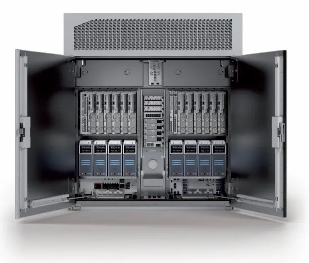
The new RBS 6000 product family is the compact multi standard Base stations used in GSM, WCDMA and LTE networks by Ericsson. It is an energy efficient compact site solution that supports different Radio Access Technologies (RATs) in a single Cabinet. The RBS 6000 is built with backwards compatibility with the RBS 2000 and RBS 3000 product lines.
As a multi-standard base station, the RBS 6000 has many options that make choices simpler by providing great freedom of choice as well as cost effective deployment and development of new, high-speed mobile broadband services, mobile TV and web applications which all require a smart solution. The RBS 6000 family not only ensures a smooth transition to new technology and functionality minimizing OPEX, but also reduces environmental impact. How these advantages are realized is described in chapter 2 in existing features.
Figure 2 Large outdoor RBS 6000 Internal units
1.2
Purpose
The results of this thesis are proposed to describe the power system functionality implemented in HW an SW with the power units (e.g. PSU, PDU and BFU), and propose improvement by new features. The summarized results will be useful for Ericsson when analyzing existing features and develop new features.
The focus has been on present features, since Ericsson wanted to list how they benefit the customer. The proposed new feature is intended to increase the value of Ericsson’s power system in the present market.
1.3
Objective
The two objective of this thesis was to analyze the power system with their present features and to find out their advantages which benefit the customer.
1.4
Method
To be able to fulfill the purpose, the power system functionality is investigated. The analysis is done of the whole power system including the modules of the power units (e.g. PDU, PSU etc) and SW control for which, enabling new features by using available information and function.
The documents which were used in analysis and study of existing systems are:
1) FS Power system control [1] 2) RS Power System [2]
3) FS climate control [4] 4) FS external alarm [5] 5) FS MMI [3]
6) EC-Bus [6]
1.5
Outline of the thesis
This part describes the formation of the report to give the reader a general idea of the thesis.
Chapter 1: In this Chapter the Background and Purpose of the thesis work is
described.
Chapter 2: This Chapter contains an overview of the power system and its
features.
Chapter 3: This Chapter contains the Proposal of new features.
2
Power system overview and Features
2.1
Power System Overview
The purpose of the power system in RBS 6000 is to supply the internal and external consumers with -48 VDC from different power sources. The power system supports three variants of incoming power as source which are:
Direct -48 VDC power supply
DC/DC conversion +24 VDC to -48VDC
AC/DC rectification with/without battery (back-up purpose)
Figure 3 Block diagram of RBS power system
The power system converts from any power source input to a consumer’s voltage that is -48 VDC. AC fed RBS has a battery backup to handle grid outages. The EC-Bus acts as a communication bus through which control and alerts are passed [1].
2.1.1 Power Battery cabinet (PBC)
The Power Battery cabinet converts AC mains power to -48 VDC voltage and supplies this to one or several RBS cabinets. Furthermore, a PBC provides optional battery backup in case of AC power failure. Depending on the backup time requirements and the quality of the AC mains electricity grid, alternative battery types and sizes can be used according to RBS requirements [2].
Battery (only for AC) AC or DC Input EC Bus -48 VDC Consumers
Power System
Figure 4 Ericsson PBC and RBS
2.2
Existing Features
One of the objectives of this thesis report was to find the features from specific units and the RBS. These features are related to customers benefit and how the features help the RBS and the PBC. In this part the authors have analyzed all the features and separated the features in some categories as follows:
Power Battery Climate Security LED handling
Configuration and Information
These above categories are described in the tables below. These categories are then explained with:
Function/Feature Description Customer Value
The function/feature column contains the slogan. Description column describes the main function of the feature and how it works.
The customer value is where it explains the feature from the customers’ point of view. The customer views are the separated into three parts as follows:
Manufacturing cost (MC) The manufacturing cost includes material cost, assembly cost, factory operating cost, testing cost etc.
Operational cost (OC)
The operational cost includes maintenance, repairs, supplies, travel and vehicle expenses, skilled site engineer, utilities, management etc. Information (IN)
The information includes the necessary data received from the internal and external devices such as voltage, current, alarm etc
These parts are rated from 0 to 3 scales where: For MC and OC (High Value means lower cost):
0 represents--- no impact on operation or manufacturing cost. 1 represents--- minimum impact on operation or manufacturing cost. 2 represents--- average impact on operation or manufacturing cost. 3 represents--- very good impact on operation or manufacturing cost. For IN (High Value means greater use of information):
0 represents--- no information used.
1 represents--- minimum information value to customer. 2 represents--- average information value to customer. 3 represents--- high information value to customer.
3
Proposed Software Features
3.1
Introduction
This chapter describes new features which can be used for future
implementation. The description contains a motivation of what each feature contains, and also how the customer will be benefited.
Most of the features have been motivated from the existing features with upgrade. Some features have been proposed with suggestion of hardware changes which is described in chapter 4. All the features have been evaluated with MC, OC and IN, which makes the proposed features easily understandable and distinguishable with the existing features.
3.2
New Features
The new features are mentioned below with details and its benefit. The ratings are rated the same way as mentioned previously in chapter 2.
3.2.1 Regional wise charging
This function will make use of GPS built in the RBS to determine the charging mode. Different region requires special charging modes, as the stability of electricity differs from country to country. The pre configured charging mode will be automatically assigned to the Power system configuration. This option will even configure the wind and solar configuration by taking data from the Wind log and solar log as mentioned in chapter 4.
Benefit
This feature will prolong the life time of the battery and help the customer to set up the RBS faster. The customer will be able to take down the OC by not needing to send a site engineer to configure the charging mode.
MC-0 OC-2 IN-2
3.2.2 External air-condition control
This function will synchronize the external Air-Condition in an internal RBS and control the air flow. The feature will allow full control of the Air-Condition and automatically lower or higher temperature of the air flow when required.
Figure 5 External air-condition control
Benefit
This feature will allow the total electricity consumption of the base station to go down as the air flow will always be set to a minimum keeping the indoor Base Station cool to the required operational temperature
MC-2 OC-2 IN-1
3.2.3 Solar panel log
Through this feature statistics of maximum and minimum power generation, average power generation of solar panel can be known. The solar panel will pass information regarding the total power and power from each panel. If there is any crack or dirt formed the solar panel log will give an alert. This log will be analyzed by a software and camera sensor [4.2.2] to precisely indentify the problem.
Benefit
The customer will be able to know how much power can be generated through the panel and according to that how much power is consumed from the grid that can also be calculated which will help the customer to keep track. Crack or dirt on the solar panel can be identified, plus any shadow being formed due to tree or building can also be traced by the solar panel log.
3.2.4 Wind data log
This option will show the status of the wind in every direction. Through this option wind speed and direction can be measured as mentioned in [4.2.3]. And also the statistics of average, minimum and maximum power generation will be known.
Benefit
The customer will be able to schedule the system according to the status. In hybrid solution [4.2] this feature is a way of lowering energy consumption from the grid which means lower electricity bill for the customer.
MC-2 OC-2 IN-3
3.2.5 Mobile Application for Site engineer
This feature will synchronize the NOC (Network operating center) and the site engineer, which will keep the site engineer up to date of specific RBS. This feature will give particular alerts and notes for the reason of site visit to the RBS along with its location. The application will be able to run in IOS, Android or windows phone.
Benefit
This function will keep the site engineer up to date and notified when required. A full status and alert will be sent to the site engineer regarding the problem identified remotely.
MC-0 OC-1 IN-3
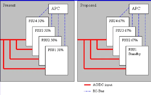
3.2.6 Raising efficiency of PSU
The process raises the efficiency of the PSU by letting the PSU to work with most efficient level. When the PSUs are working with the most efficient level the power can be saved.
Figure 6 Example of raising the efficiency of PSU
Benefit
This function allows the PSU to work with a recommended load which raises the efficiency of the PSU.
4
PLC and Hybrid Solutions
4.1
Power line communication
Power Line Communication (PLC) is a communication technology through which data’s can be sent over existing power lines. Which means through existing power cables data’s can be sent and received and it can also power up the devices at the same time. Power line communication technologies are being used widely for different applications.
As PLC does not need any extra wiring and it works with the existing cable and also provides fast communication between devices. Table 1 shows the data rate using power line communication using a 2.55mm thick wire of 2.6m in length. It can be observed from the table that the data rate of 200 Mbps can be achieved without error and a maximum 480Mbps [8] can be achieved with an approximate 10% PER. The PER is the Packet error rate.
Table 1 Data rate in using PLC [8].
PHY data rate(Mbps) PER(%)
53.3 0 106.7 0 160 0 200 0 320 0.1-0.2 400 5.6-8.7 480 9.1-11.3 Types of PLC
There are two types of Power Line Communication, which are: PLC over AC lines
PLC over DC lines
These both AC and DC line communication are required for PLC.
4.1.1 How will PLC work
PLC is like any other communication technology where the data’s which are needed to be sent are modulated by a sender then insert it onto medium.
4.1.2 Modulation Technique
Many modulations schemes can be used in PLC. Such as: Orthogonal Frequency Division Multiplexing (OFDM), Binary Phase Shift Keying (BPSK),
Spread-FSK (S-FSK).
Out of these 4 modulation schemes orthogonal frequency division modulation (OFDM) is most suitable for this operation in PLC [7]. It provides high rates of data communication, with the use of numerous frequencies for transmitting data at the same time. Moving this data across power line enables remote connection. OFDM allows high data rates using low frequency carriers. Through the use of OFDM techniques data rates up to 125 Kbits per second are feasible using carriers in the frequency range of 3–95 kHz higher carrier frequencies are also possible and allow increasing bandwidth.
4.1.3 Application of PLC
PLC is widely used in the Smart Grid and in micro-inverters. As the market gets familiar with this technology, PLC is also introduces to electronics in cars, transportation and public uses such as:
Lighting control (traffic light control, LED dimming),
industrial use (UPS communicating to a network device, irrigation control), Machine-to-Machine communication (vending machines, a hotel’s
reception-to-room communication).
Transport (Electronics in cars, trains and airplanes) Data centers are using this power line communication.
4.1.4 Benefits and drawbacks of PLC
Advantages of PLC: Mobility Flexibility
Ease of installation for indoor setup Stability
Complements both cable and wireless solutions Disadvantages of PLC:
Installation and high performance depend on the architecture of the electrical network
Lack of standards and guidelines
4.2
Hybrid solution
As the need for connectivity continues to grow widely, more telecommunications equipment such as RBS devices are installed in urban as well as remote
locations. Small wind turbines can be cost-effective when powering such
telecommunication sites. The solution uses different power supply systems, such as the Solar Power System, Hybrid Power System, wind etc to maximize the use of renewable resources. Below are some other options which can be used to create a hybrid RBS.
4.2.1 Diesel generators and Battery Hybrid Solution
In some Ericsson site, power mainly comes from diesel generators. Maximizing their working efficiency has become a major issue in the industry. Battery Hybrid Solution reduces fuel consumption by more than 50%. This solution uses an intelligent monitoring (as seen in figure 16) and setting up system to plan the Diesel generator and storage batteries based on the generators efficiency, load power, and battery capacity to ensure high efficiency. The generator only needs to start for longer AC failures. With diesel generators together with batteries half of the fuel consumption can be reduced [13]. The Opex can be reduced as well with such advantages as lower energy consumption, reduced maintenance, and long service life.
Figure 7 Diesel generators and Battery Hybrid Solution Vs AC failure plot.
4.2.2 Solar Energy
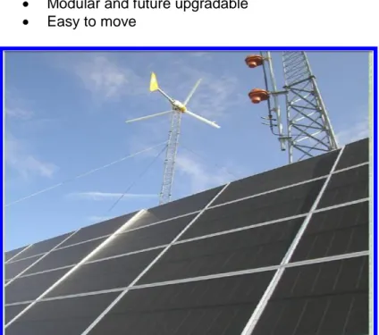
Solar energy systems are increasingly used for a variety of applications, among them new telecommunication converging technologies. Solar energy has proven to be a reliable and economical method of powering telecommunication systems in places where conventional electricity is unavailable or impractical. It provides an excellent source of clean, reliable power to keep batteries charged. And through solar energy the power consumption from the grid can be reduced which is low cost solution for Ericsson.
There are several advantages of using solar, such as: Low maintenance costs
Reliability and durability
Environmental friendly - Green Energy Noise free
Modular and future upgradable Easy to move
Figure 8 Solar Solution
Basic feature of a Solar Panel
Below are some basic features which can be obtained from Solar panel. Crack detection [14].
Shadow detection.
Input power from each cell panel.
The solar panel crack detection and shadow detection is a detection process which is done through using a camera sensor placed on top, over the panel [9]. This sensor can detect any small crack that can degrade the performance of the solar panel. The same sensor can also detect shadows, which can produce with time. The shadows can be produced from a nearby building construction or an obstacle of a tree.
4.2.3 Wind Energy
Wind power secures reliable power supply, which is crucial for telecom services. Small wind turbines can be used to produce the electricity for telecommunication. It can be cost-effective Wind power provides power supply to telecom services and reduces the need for maintenance such as fuel, equipment transportation etc. The grid connectivity is unavailable in many locations. Through wind energy these locations can be served. Or using wind energy with diesel generator / batteries will be a cost effective solution. As it have many benefits. Such as:
Power generation in different variation of wind range
Robust and reliable ,uninterrupted power generation except when the wind does not blow
As seen in figure 18. Small scale turbines can be mounted on 30m towers. Wind Energy can vary from different heights of turbines ranging from 15m - 40m. The required height for RBS is 30m for its 10kw.
Basic Features of a Wind Turbine
Measures the wind speed and transmits wind speed data to the controller to calculate power generation. This information can be used to utilization of diesel generator and battery.
5
Conclusion
5.1
Observation from Existing Feature
One of the goals of this thesis is to collect information regarding the existing power system and its features. Most of the present features are found from Ericsson’s internal FS and RS documents which have been classified into power, battery, climate, security, LED handling and information and configuration [2.2]. Features regarding power are mainly focused on supervision and information of main power and the control of the system voltage. It could be seen that most features in the power and battery are focused in gathering information and sending alarms. This includes different charging modes, processing test and logs which helps to prolong battery life time.
Other than the features regarding battery and power, the features from climate, security, LED handling, information and configuration are mostly information based where climate deals with collecting hotspot temperatures and some configuration features of controlling and setting fan speeds.
5.2
Observation from Proposed Feature
Another goal of the report was to find features which could benefit the power system and the customer with cost. The proposed features are mostly focused on bringing a good impact on manufacturing cost (MC) and operational cost (OC). In some cases, there are features which come with good information (IN) sharing. By using hybrid solution customers will be able to lower the electricity by suiting up the power system with different environments, providing high battery backup. The power system will also be able to communicate with the solar panel and sense the power from the sun. The solar panel will also be able to give
information of future shades being formed or even cracks with camera sensor. The wind turbine will be able to pass on information regarding wind speed and direction. This information from the wind turbine together with the solar can be used to predict the weather conditions with the help of software.
Reference:
[1] Justinian Anatory and Rajeev Thottappillil, “Effects of Multipath on OFDM Systems for Indoor Broadband Power-Line Communication Networks,” IEEE Trans. Power Del., vol.24, no. 3, pp. 1190 - 1197, Jul 2009.
[2] Masood Ur Rehman, Shihua Wang, Yanchao Liu, Shuxian Chen,Xiaodong Chen, and Clive G. Parini, “Achieving High Data Rate in Multiband-OFDM UWB Over Power-Line Communication System,” IEEE Trans. Power Del., vol.27, no. 3, pp. 1172 - 1177, Jul 2012.
[3] Wu-Ja Lin ,” Automatic Detection of Internal defects in Solar Cells”
Instrumentation and Measurement Technology Conference (I2MTC), IEEE, pp. 1 - 4, May 2011.
[4] G. Fabbri ,A. J. M. Cardosol, C. Boccaletti, A. Girimonte ,” Control and Optimisation of PowerConsumption in Radio Base Stations”
Telecommunications Energy Conference (INTELEC), 2011 IEEE 33rd International, PP.1-6,Oct.2011
[5] C. Boccaletti, G. Fabbri, E. Santini “ Innovative Solutions for Stand Alone System Powering”, Telecommunications Energy Conference, 2007. INTELEC 2007. 29th International,pp. 294 – 301, Sept 2007
[6] Ferreira, H.C.; Grove, H.M.; Hooijen, O.; Han Vinck,
A.J.,”Power line communications: an overview”AFRICON, 1996., IEEE AFRICON 4th Vol. 2 ,pp.558 - 563 ,1996
[7] Bajpai, P.; Prakshan, N.P.; Kishore, N.K. “Renewable hybrid standalone telecom power system modeling and analysis”,TENCON 2009 - 2009 IEEE Region 10 Conference ,pp.1-6,2009
[8] Aghamohammadi, A.H.; Prabuwono, A.S. ; Sahran, S. ; Mogharrebi, M. “Solar cell panel crack detection using Particle Swarm Optimization algorithm”Pattern Analysis and Intelligent Robotics (ICPAIR), 2011 International Conference ,Vol. 1,PP.160-164, June 2011
[9] Aalamifar, F. ; Hassanein, H.S. ; Takahara, G. ,” Viability of Powerline Communication for the Smart grid”Communications (QBSC), 2012 26th Biennial Symposium ,pp.19-2May 2012
[10] Gao Yi ;Sun Guiling ; Li Weixiang ; Pan Yong ” Wireless Sensor Node Design Based onSolar Energy Supply”,Power Electronics and Intelligent Transportation System (PEITS), 2009 2nd International Conference ,Vol. 3,pp.203-207,Dec. 2009
[11] Rahnema, M.,"Overview of the GSM system and protocol
architecture".Communications Magazine, IEEE ,Volume: 31 ,Pp. 92 - 100,1993 [12] http://lit.powerware.com/ll_download.asp?file=Understand+Hybrid+Generator+
%E2%80%93+Battery+Systems+white+paper_A.pdf
[13] http://www.tekes.fi/fi/gateway/PTARGS_0_201_403_994_2095_43/http%3B/tek
es-ali1%3B7087/publishedcontent/publish/programmes/groove/documents/seminaar iaineistot/investorboard2011/darrox__june_2011.pdf
[14] http://etc4ca.com/projects/basic-features-of-a-wind-turbine [15] http://www.siacwindenergy.com/the-tower.php


![Figure 9 Wind Solution [21]](https://thumb-eu.123doks.com/thumbv2/5dokorg/5500708.143249/24.918.283.781.445.947/figure-wind-solution.webp)
