Västerås, Sweden
DVA333 - Thesis for the Degree of Bachelor of Science in
Engineering - Computer Network Engineering, 15 credits
DYNAMIC BANDWIDTH ALLOCATION FOR
WIRELESS NODES WITH SOFTWARE
DEFINED NETWORKING IN
HETEROGENEOUS NETWORKS WITH
EMBEDDED SYSTEMS
Thomas Jädal
tjl16001@student.mdh.seDirk Postol Dissel
dpl16001@student.mdh.seSupervisor: Mohammad Ashjaei
mohammad.ashjaei@mdh.seMälardalen University, Västerås, Sweden
Supervisor: Svetlana Girs
svetlana.girs@mdh.seAbstract
In the wireless computer networks of today, there is a limitation on how wireless access points handle bandwidth distribution to wireless nodes, both in Software Defined Networking (SDN) solutions, traditional networks with routers and switches, and in embedded systems. The limitation is the lack of control of the node bandwidth usage. Quality of Service exists, but it limits the bandwidth on the access point or the switch and not on the node itself. Thus, when several nodes connect to a single wireless access point, they compete for bandwidth, and therefore there is a need to allocate bandwidth to the nodes directly. Through the use of SDN, it would be possible to make this dynamic access control work with rapidly changing networks, both wired and wireless. This thesis is a proof of concept with actual hardware, and answers the question on how we can implement dynamic bandwidth allocation in a heterogeneous network with SDN and how to make it dynamic with the adding and removal of nodes. The solution achieves the dynamic bandwidth allocation by running a program in parallel to the SDN controller together with additional software on the nodes. The solution makes it possible to share the bandwidth between nodes and through priorities manipulate how much of the total bandwidth each node receives in comparison to the other nodes. The measured results show that the program has a manageable overhead and works with several nodes. The thesis aims to widen the view on viable SDN approaches and inspire future research on wireless SDN solutions.
Contents
1 Introduction 1
1.1 Problem Formulation . . . 1
2 Background 2 2.1 Traditional Networks . . . 2
2.2 Software Defined Networking . . . 2
2.2.1 SDN Controllers . . . 4
2.2.2 OpenFlow . . . 4
2.2.3 Open vSwitch . . . 6
2.3 Quality of Service (QoS) . . . 6
2.3.1 Wireless and QoS . . . 6
2.3.2 Enhanced Distributed Channel Access (EDCA) . . . 7
3 Related Work 8 4 Method 10 5 Design 11 5.1 System Architecture . . . 11 5.2 Meter Tables . . . 12 5.3 Final Design . . . 12 5.4 Algorithm Design . . . 14 6 Hardware 15 6.1 Raspberry Pi . . . 15 6.2 Zodiac WX . . . 16 6.3 Zodiac FX . . . 17 7 Software 18 7.1 Zodiac FX . . . 18 7.2 Zodiac WX . . . 18 7.3 Raspberry Pi . . . 18 7.4 Choice of Controller . . . 19
7.5 Admission Control Mechanism . . . 19
8 Experiments 20 8.1 Test Scenarios . . . 20 8.2 Scenario measurements . . . 21 8.3 Measurement limitations . . . 22 9 Results 23 9.1 Scenario 1 - Results . . . 23
11 Conclusions 28
References 29
Appendix A Zodiac WX Installation and Setup 31
Appendix B Zodiac FX Installation and Setup 33
Appendix C Raspberry Pi Installation 34
List of Figures
1 Illustration of control plane separation in SDN . . . 3
2 SDN components and API communication between planes . . . 3
3 OpenFlow Switch architecture [14, p. 11] . . . 5
4 Network System Model [22] . . . 8
5 Development process . . . 10
6 Proposed systems architecture . . . 11
7 Flowchart of admission control mechanism . . . 13
8 Raspberry Pi 3 Model B+ [26]. . . 15
9 Raspberry Pi 1 Model B Revision 2 [27]. . . 15
10 Zodiac WX Access Point [28]. . . 16
11 Zodiac FX switch [30] . . . 17
12 Overview of overhead measurements . . . 22
13 Throughput test (TCP) for Scenario 1 . . . 23
14 Throughput test (TCP) for Scenario 2 . . . 24
15 Overhead in ms for implementation of bandwidth control . . . 25
16 Overhead in ms for algorithm . . . 25
17 Interface for setting the wireless region. It’s set to SE in this thesis. . . 31
18 Firewall zone settings . . . 31
19 Adding the custom files to the backup configuration . . . 32
List of Tables
1 Host devices used in experiments . . . 202 Scenario 1 - Experiment setup . . . 20
3 Scenario 2 - Experiment setup . . . 21
1
Introduction
Today, computer networks are an essential part of our everyday life. The infrastructure of traditional networks consists of network devices containing their own control of management and forwarding of data [1]. These devices are individually configured on how to manage the flow of data. As a progress to the traditional approach, Software Defined Networking (SDN) decouples the management and forwarding from network devices to a centralised
controller.
In a traditional computer network, the control and management of devices are usually done through a command line or a graphical interface for the specific device [1]. When using SDN, an administrator has the ability to control and manage several devices at the same time through a single graphical interface on an SDN controller. This results in a more efficient management and configuration solution. There are several parameters that an administrator can change by using SDN, and one of those is bandwidth. It is however limited by static assignment. For example, a node will always have 5 Mbit/s, or 10 Mbit/s whether the bandwidth is utilised by a data flow or not. This static assignment limits the maximum number of possible nodes in the network due to the fact that bandwidth has an upper limit and the nodes might not always use the allocated bandwidth, therefore wasting it. If varying amounts of data needs to be sent from different nodes in a network, there is a need to make the bandwidth assignment dynamic for different data flows as well as a dynamic admission control. If a node could request a certain amount of bandwidth from the SDN controller based on an estimated need of the flow it is about to send, it would either get permitted or denied depending on the current utilisation of bandwidth. In order for the bandwidth allocation to be dynamic, it has to be done during run-time and nodes should have the ability to request both more and less bandwidth when needed. This would have to work for both wired and wireless nodes to increase scalability. This system would have a more efficient use of network resources because the controller will have the ability to permit or deny the request for increased or decreased bandwidth. Therefore, the motivation for creating such a network solution is the prevention of the overutilization of bandwidth from nodes, and the creation of a more scalable and manageable network.
1.1 Problem Formulation
The thesis revolves around the problem of designing and implementing a dynamic admission control for bandwidth utilisation in a heterogeneous network, which is a network where wired and wireless channels coexist. As networks today grow and companies strive for optimisation, the allocation of bandwidth to host devices is something that should be considered. Without a form of admission control for bandwidth, hosts might end up bottlenecking the throughput of other host devices. As previous works [2], [3], [4] have been done regarding admission control our focus will lean towards the wireless part. Thus, the main goal of this thesis work is to investigate the ways to provide dynamic admission control for wireless nodes in heterogeneous SDN networks. In particular, we will focus on
2
Background
This section will describe the differences between traditional networks and Software Defined Networking together with OpenFlow.
2.1 Traditional Networks
In a traditional network, each network device (a switch or a router) makes its own decision on how to forward incoming packets [5, pp. 2-25], [5, pp. 151-223]. Switches make forwarding decisions based on the destination Media Access Control (MAC) address and routers make forwarding decisions based on the destination Internet Protocol (IP) address. Switches acquire the data required to make the forwarding decisions by adding the source MAC address together with the receiving port to the Content Addressable Memory (CAM) table [5, pp. 2-25]. When the switch receives a packet, the switch looks up the MAC address in the CAM table to figure out which port to forward the packet through. If the MAC address isn’t listed, the switch floods the packet out through all the ports except the receiving port and binds the source MAC address to the port in the CAM table for use in future packet streams. A router acquires the data needed to make forwarding decisions by consulting the routing table and by reading the destination IP address in the received packet [5, pp. 151-223]. The routing table is where the router stores all of the known networks. In order to forward packets to the correct destination, the router compares the destination IP address in the packet to the entries in the routing table. If there is a match, the packet gets forwarded out through the correct port. If there is no match, the packet gets dropped.
2.2 Software Defined Networking
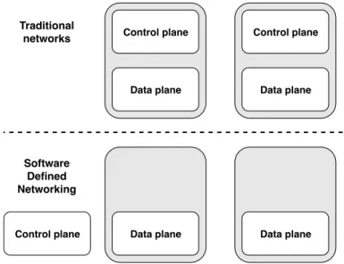
SDN is a new way to configure networks [6]. The difference of SDN in comparison to traditional networks is that SDN enables administrators to directly program network devices from a centralized network controller. In SDN, the control plane of network devices is transferred to a centralized SDN controller as shown in Figure 1, which negates the difficulties in network management. SDN consists of three different planes of operation: application plane, control plane, and data plane.
The application plane consists of different applications that communicate with the SDN controller [1]. Applications can collect information from SDN Controllers to build an abstracted view over the network and to collect other relevant information that, e.g., can be used for security or network management. The control plane is the intermediate plane between the application and data plane. The control plane consists of an SDN controller that manages the configuration of network devices in the data plane. The SDN controller receives information from applications and relays them to associated network devices. The SDN controller also collects information and makes statistics about network devices in the data plane and sends them back to the applications. The Data plane consists of network devices that process and forward packets. The networking devices in the data plane forward packets based on configurations given by the SDN controller.
The three different planes in SDN communicate via application programming interfaces (API) as shown in Figure2. SDN utilizes two types of APIs for communication: northbound API and southbound API [1], [6]. The northbound API is used for communicating between the SDN controller and applications while the southbound API, such as OpenFlow, is used to communicate with network devices in the data plane. APIs align with the concept of programmable networks as the APIs enable administrators to directly program network configurations instead of using CLI or vendor-specific interfaces.
Control plane
Data plane Control plane
Data plane
Data plane Control plane Data plane
Software Defined Networking
Traditional networks
Figure 1: Illustration of control plane separation in SDN
Applications SDN controller
Application plane
Control plane
Southbound API Northbound API2.2.1 SDN Controllers
The SDN controller acts as the brain of the SDN architecture [1], [7]. It is an entity whose purpose is to manage SDN enabled network devices and application resources. The SDN controller is a software, which typically contains modules that can be enabled for specific purposes. It could be to manage the flows of different devices or handle application tasks. In SDN networks, the controller handles flows in different operational modes: proactive, reactive or a mixture of both. As the controller is a centralized unit that manages multiple switches the design and performance of the SDN controller also affect the performance of the network. The list of common SDN controllers is presented below:
Floodlight Floodlight is an Open Source OpenFlow controller that can be used in SDN [8]. Floodlight is java-based and allows administrators to configure and load various modules for specific purposes with high performance as its design is multi-threaded.
OpenDaylight OpenDaylight is an open source Java-based SDN controller with support for OpenFlow [9]. The OpenDaylight controller is run through a Java Virtual Machine (JVM) and can be deployed on any device as long as Java is supported.
Ryu Ryu is an open source controller that supports OpenFlow [10]. Ryu is component-based designed with well-defined API’s to enable easily deployed configurations and applications. The Ryu controller is written entirely in Python.
NOX NOX is one of the first open source SDN controllers [11]. The NOX controller supports OpenFlow version 1.0 and is written in C++. An older version of NOX Classic also had support for Python.
POX POX is an open source controller with support for OpenFlow 1.0 [12]. The POX controller is written in Python.
2.2.2 OpenFlow
OpenFlow is both a communication protocol and a specification of the logical structure of the network switch [13]. The architecture can be seen in Figure3. OpenFlow is used between the control plane and data plane between the SDN controller and network devices. In order to keep the communication secure, OpenFlow uses Transport Layer Security (TLS) to provide both privacy and data integrity in the network [14, p. 38]. Each network device connects to other OpenFlow network devices and if possible, to the end devices themselves.
Figure 3: OpenFlow Switch architecture [14, p. 11]
The OpenFlow technical specification defines three types of tables: one or multiple flow tables, the group table, and a meter table [14, pp. 18-37]. Information about the different types of traffic flows is stored within the flow table. A flow is a stream of packets with the same header information such as packets with the same VLAN, from the same source IP address or network, to the same destination address or network and so on. The header information in the packet is matched against a specific entry in the flow table and only the controller can add or remove flow entries in the flow table. Both the group table and the meter table can trigger a variety of actions affecting one or multiple traffic flows, but the group table is used for grouping several flows into one or several groups, while the meter table is used for Quality of Service.
The OpenFlow protocol enables the controller to send configuration commands to update the flow entries in the flow table [14, pp. 38-41]. The specification defines three types of messages: Controller-to-Switch, asynchronous, and symmetric. Controller-to-switch messages are initiated by the controller and are used to manage the switch by changing anything related to the configuration or flow table entries. They may or may not require a response from the switch depending on the contents of the messages. These messages are used for inspecting the state of the switch as well. Asynchronous messages are initiated by the switch and sent without consulting the controller first and are used to notify the controller of the first packet in a flow or if the switch changes its state. Symmetric messages are sent by both the switch and controller without solicitation in either direction (for example keepalive messages).
2.2.3 Open vSwitch
Open vSwitch (OVS) is software which implements a multilayer switch and runs on Linux [15]. OVS supports several features such as OpenFlow traffic handling, 802.1Q VLAN tagging, and Spanning Tree Protocol [16]. With OVS, devices such as access points can operate with the functionality of a switch. With the OpenFlow support, an access point running OVS can be integrated into an SDN topology. OVS runs with the assistance of a kernel module, but can run completely in userspace if required, but with a performance loss. OVS enables configuration of virtual interfaces and bridges and can be run through virtualisation software such as VirtualBox and KVM.
2.3 Quality of Service (QoS)
Quality of Service refers to a networks ability to manage the flow of traffic and other types of performance elements such as latency, packet loss, throughput or network uptime [17]. The concept of QoS also includes the ability to manage the resources of a network by different priorities for various types of traffic. To cope with the increasing demand the performance of the network must scale with it. With QoS, measures can be taken to provide, e.g., better throughput and allocation of bandwidth.
To manage QoS, there are different architectural models such as Integrated Services (IntServ) [18] and Differentiated Services (DiffServ) [19]. DiffServ does not differentiate traffic based on individual flows, instead, specific traffic classifications are applied. These classifications allow traffic to be priorities on a per-hop behavior. IntServ, on the other hand, makes use of Resource Reservation Protocol (RSVP) to apply priorities to specific end-to-end traffic flows.
2.3.1 Wireless and QoS
Various wireless standards exist for different purposes. For example, wireless sensor networks or wireless local area networks. The different standards rely on different Medium Access Control (MAC) mechanisms to deal with collisions, such as TDMA or CSMA. In this work, the focus will be on the IEEE 802.11 standard, also known as WiFi. IEEE 802.11 is a standard that was launched in 1997 for wireless networks and uses the 2.4 and 5 GHz frequency bands [20]. Each frequency band has been divided into a different number of channels so that several units can function better in the wireless medium without interfering with each other.
Within a WiFi network, devices use Carrier-Sense Multiple Access with Collision Avoidance (CSMA/CA) [21]. It is a method used by wireless network devices to avoid collisions between broadcasts. Because wireless devices can transmit and receive data but not at the same time, collisions cannot be detected in the same way as in an Ethernet cable. Communication in Ethernet takes place in full duplex, which means that transmission and reception of data can be done simultaneously. The CSMA/CA method works by a device listening to the wireless media to determine if another device is transmitting. If no transmission occurs, the device can transmit. If there are two or more units within the same wireless network, there is a risk of collision if both units choose to transmit at the same time. If this collision is detected, both units wait for a random time called backoff before trying to transmit again. The likelihood of collisions occurring during the second transmission attempt is smaller because the devices are unlikely to have chosen exactly the same backoff time, however, the risk of collisions with more wireless devices increases. As an optional add-on in CSMA/CA, Request to Send (RTS)/Clear to Send (CTS) is available. It is a mechanism that wireless nodes can use to ensure that they are allowed to transmit over the wireless media by asking the access point if they receive transmission permits with an RTS. If the wireless device receives an acceptance response from the access point with a CTS, the device can send data without worrying about collisions with other devices that it cannot detect itself. Since the CTS is sent from the access point, all wireless devices connected to it will hear that message, which means they wait to send data if they have not sent an RTS first.
2.3.2 Enhanced Distributed Channel Access (EDCA)
In 802.11e enhancements to the backoff mechanisms were made [4]. In EDCA the waiting time of transmitting nodes is applied differently depending on priority levels. Higher priority will result in a shorter backoff time. Instead of starting the backoff time at collisions regardless of who is sending, data traffic in EDCA with higher priority will be sent while lower priority data traffic acts as if a normal collision occurred and starts its backoff time.
3
Related Work
A study by Wang and Shi [22] explores the topic of SDN based bandwidth control technology. The study that they performed combines bandwidth control with a token bucket mechanism in SDN where the allocated bandwidth is based on priority levels of different users. The simulation system consisted of three host devices, one server, two Open vSwitches and a Floodlight SDN controller as depicted in Figure4. Simulations were performed were three host devices received different priority levels. As hosts simultaneously accessed the server they competed for the limited bandwidth. The mechanism used to control the bandwidth allocation used the bucket mechanism to limit the throughput of devices when the limit was reached. The results from the simulations showed an improvement in throughput corresponded to assigned priority compared to a first-come-first-served approach. The conclusion was that it is useful to combine bandwidth control with programmable networks and future works suggested an implementation with a more dynamic and flexible approach.
Figure 4: Network System Model [22]
Fu et al [17] studied another concept of guaranteeing bandwidth based on priority levels. Similar to the previous study, they use priorities to allocate different bandwidth levels. Their simulation model consists of Open vSwitches and virtual networks instead of single host devices. For the controller, the authors used Ryu SDN-controller. In their implementation, they used a token based queuing technique to allocate different priorities on Open vSwitches. The results from their simulated experiments show an efficient method where bandwidth is allocated by priorities and adjusted with adding and removing of nodes. Their conclusions state an efficient method of bandwidth utilization and propose future work oriented on the meter tables in OpenFlow 1.3.
A study by Jiménez et al [2] analysed wireless admission control with SDN. They used simulations to evaluate QoS parameters such as throughput and delay. In their experiments, they used a simulated access-point with Open vSwitch to allow OpenFlow communication to an SDN-controller. Their implementation used an algorithm to populate the flow-table on their AP and compared results to nodes without their application. Their results showed a better throughput with a wireless SDN network and a delay that initially were inadequate, but improved with a scaling of nodes.
A previous study by Kailayanathan and Norling [3] explored the topic of bandwidth allo-cation in heterogeneous SDN-networks. They aimed to provide an access control mechanism were network resources were efficiently used in an SDN-network. Their implementation used static allocations based on priority levels. Their experiments provided results that showed a functioning admission control mechanism, as well as useful conclusions regarding hardware limitations.
The above-mentioned works presented a good concept of implementing bandwidth allocation with SDN. The studies were done with simulation tools which might neglect unforeseen difficulties. All studies concerned some aspects of our proposed work. However, the mentioned works are lacking a proper evaluation based on an implementation in an SDN controller. The study by Kailayanathan and Norling [3] used similar hardware, which made their research quite relevant. Their conclusion and future work provided solid underlying information on reaching a feasible solution. In our thesis, we will not only focus on designing and admission control in an SDN controller for wireless hosts, but also we provide a proof of concept by implementing the proposed solution on a selected SDN controller.
4
Method
The scientific method that we will use in this thesis is the experimental method, which is going to be used to verify our results. The different steps from start to finish is illustrated in Figure 5. Previous work has been done on static assignment of bandwidth to nodes through the use of SDN by two other students, Kailayanathan and Norling [3]. Therefore, the first task will be a literature study on their work as well as other related work. The results from this analysis will be used to see what can be improved upon. Then we need to learn and understand how the equipment and software works and in what ways we can program it to make the desired changes. This includes studying the OpenFlow and the controller documentation. The results from our studies will be used in designing our own system. After the design we will perform tests, which will help in verifying and testing the thesis. If the results are inconclusive we will redesign our system, otherwise the thesis will be validated.
Literature Study
Design System
Build System and Perform Tests
Analyze Results
Validation
Conclusion
5
Design
Following section describes the topology and different approaches, leading to the finalised design before implementation.
5.1 System Architecture
The network we assume has two parts, one wired and one wireless. The nodes should prefer-ably be open-source devices, for example, Raspberry Pi or other single-board computers. Support for both wired, wireless 2.4 GHz and 5 GHz frequency bands is preferable, as it enables us to test our implementation with both wired and wireless nodes. Figure6 shows the proposed architecture for our implementation. The controller will be placed on a laptop for testing purposes and ease of configuration, but which one of the controller software we will decide to use has not been decided yet. Preferably we would like to use software that can run on a Raspberry Pi, has features that enable it to control the meter table on the access point and switch, and is easy to work with. If the controller has to be programmed, it would be preferable if it is written in a programming language we master in order to minimise errors. Thus, controller software written in either Python or C would we optimal in this situation. Concerning performance, since this topology is more of a proof of concept rather than a network with high performance as a requirement, high performance of the controller isn’t a priority, but in order make our solution as scalable as possible in the future, a revised decision on which controller software to use might be necessary. Both the Zodiac FX and Zodiac WX use open source firmware and are SDN enabled with OpenFlow implemented. Zodiac WX Wireless AP Zodiac FX Switch SDN Controller Cisco 2960 Switch
Wired OpenFlow traffic Wired normal traffic Wireless normal traffic
5.2 Meter Tables
The meter tables used in OpenFlow version 1.3 and later, offer a viable approach to imple-ment aspects of QoS on networks [14, pp. 34-37]. With the meter tables, restrictions on the bandwidth usage of specific end-to-end flow entries can be configured. An implementation for admission control using the meter tables in OpenFlow version 1.3 was tested. With meter tables, the bandwidth restrictions were managed on the switch, with actions such as packet-drops instead of nodes restricting themselves. Although restrictions on bandwidth usage were achieved, the implementation with meter tables used a static bandwidth restric-tion on specific flows, the solurestric-tion with meter tables did not validate the research quesrestric-tions described in Section1.1.
5.3 Final Design
After discarding an implementation that makes use of meter tables, a final design was made to ensure a dynamic and smart admission control. The main focus for the implementation was that nodes should be smart enough to realize their bandwidth restrictions and not compete for the medium and let the forwarding devices drop packets. Favourably the final design was to achieve a dynamic bandwidth allocation that was scalable with the adding and removal of hosts, and if possible the nodes themselves should not have to reset or terminate current sessions to allow a seamless bandwidth restriction during run-time.
The goal of the design was to offer the requested bandwidth to nodes if available. If the requested bandwidth was already reserved to other nodes an algorithm was going to be used to calculate the bandwidth allocations to nodes. The algorithm would need to consider the currently available bandwidth and distribute it according to priority levels.
Figure7 depicts the design. The clients will first send a request to the controller with the requested bandwidth and its priority level. When the controller receives the request it will register the client with the received parameters. The controller will thereafter check if the requested bandwidth is available. If it is available the client will be registered with the allocated bandwidth. If the bandwidth is not available the current usage and priority levels will be checked and run through an algorithm to determine the bandwidth allocation for each host. Once the algorithm is completed the clients will be re-registered with the new bandwidth allocations. The clients will restrict their own bandwidth according to the amount received from the controller. If the clients stop transmission or disconnect at any point, the client will be de-registered on the controller and run through the algorithm again.
Request BW with associated priority
CLIENT SIDE CONTROLLER SIDE
AP recieves BW request and sends to
controller
Register client with requested BW and coherent priority Lock bandwidth to amount recieved from controller BW avalible? Check avalible bandwidth and priority levels NO Run through BW algorithm Register BW
allocation and send to client
YES
Re-register clients with new BW based
on algorithm Send new BW
allocation to clients
If stops transmission Start transmission
De-register client and its BW allocation
5.4 Algorithm Design
The main part of deciding the per-host bandwidth will be the maximum bandwidth. Maximum bandwidth is the threshold of which the total amount of allocated bandwidth is not allowed to exceed. The threshold for maximum bandwidth is assigned at the controller.
The algorithm first calculates the priority levels and current bandwidth allocation of all registered clients. If the total amount of requested bandwidth is below the threshold of maximum bandwidth, clients will receive the amount requested. Should the total amount of requested bandwidth exceed the maximum bandwidth, bandwidth will instead be calculated depending on priority levels. The maximum bandwidth will be divided into the total number of priority levels. Clients receive the amount of bandwidth based on their priority level times the divided number according to the following equations:
B = Bandwidth (kbps)
Bmax= Max amount of bandwidth (kbps)
Breq= Requested bandwidth (kbps)
Treq= Total amount of requested bandwidth (kpbs)
P = Priority level
Pall = All combined priority levels
B = Breq if: Treq≤ Bmax
B = P ×Bmax Pall
6
Hardware
This section will describe the hardware used in the implementation as well the hardware characteristics and viability to our research.
6.1 Raspberry Pi
The Raspberry Pi is a small single-board computer developed by the Raspberry Pi foundation [23]. The Raspberry Pi can run multiple operating systems by different vendors, but the operating system that is supported by the Raspberry Pi foundation themselves is Raspbian [24]. It is a Linux distribution with an optional Desktop environment and software [25]. The two Raspberry Pi used for the wireless and wired part respectively are the Raspberry Pi 3 model B+ (RPi3b+) and the Raspberry Pi 1 model B (RPi1b). The RPi3b+ has a wireless chip that supports both 2.4GHz and 5GHz in the 802.11b/g/n/ac standards [26]. The decision to use the Raspberry Pi was made because they are cheap, easily modified both in hardware and software, have a very large community, and extensive documentation. The latest Raspberry Pi also supported both 2.4 GHz and 5 GHz, which enables us to test the final design with both frequency bands if needed.
6.2 Zodiac WX
The Zodiac WX, shown in Figure 10, is an SDN-enabled access point manufactured by Northbound Networks [28]. It comes equipped with two Gigabit Ethernet ports and runs the Linux distribution OpenWRT (version 17.04), with a custom software suite that includes Open vSwitch 2.10, and a custom Web User Interface. The Zodiac WX supports many thousands of packages due to running OpenWRT, which makes customisation easy and enables the Zodiac WX to function as a completely different networking device (such as a VPN server, proxy or other). Since firmware update 1.20, the OpenFlow functions have been replaced by Open vSwitch [29]. The main reason for this change was the increase in stability and compatibility with OpenFlow controllers. The ability to use OpenFlow, the flexibility of OpenWRT and Linux were the main reason for choosing the Zodiac WX access point.
6.3 Zodiac FX
The Zodiac FX, shown in Figure 11, is manufactured by Northbound Networks [30] and is an OpenFlow enabled switch that started out in 2015 as a Kickstarter campaign. The main purpose of the Zodiac FX was to make an affordable platform on which people can experiment on with SDN. Zodiac FX has four 10/100 Mbps Ethernet ports and is powered by micro USB. The Zodiac FX switch supports OpenFlow versions 1.0 and 1.3, and is compatible with any SDN controller using OpenFlow as the communication protocol. The low cost compared to equipment from large corporate companies and the open source firmware made this switch viable for our research.
7
Software
This section will describe the software utilisation done from start to finish with appropriate sections for each device.
7.1 Zodiac FX
The Zodiac FX switch is installed according to instructions in AppendixB. Port 4 on the Zodiac FX switch is connected to the Cisco 2960 Switch and used for OpenFlow traffic to and from the controller. Port numbers 1, 2, and 3 are used to forward normal data-traffic. Port 3 is connected to the Zodiac WX while port 1 and 2 are used to connect the wired Raspberry Pi hosts. Due to a bug in the GUI, all configuration and management are done through the Command Line Interface. In the current firmware version (0.84), it’s not possible to assign VLANs to ports using the GUI at all. Most of the configuration commands can be found in the official Zodiac FX user guide.
7.2 Zodiac WX
The Zodiac WX is installed according to Appendix A. The Zodiac WX WAN port is connected to the Cisco 2960 Switch according to Figure6and the LAN port is connected to port 3 on the Zodiac FX. During the installation process, several limitations were discovered that weren’t apparent from the beginning. The limitations of the Zodiac WX are the low storage capacity (8 MB of free space after a factory reset). Therefore, the ability to customise, add, or update packages is limited. For example, just installing python3-minimal and vim reduced the available storage capacity to 2 MB. Another limitation is that the wireless radios are occasionally refusing connections despite correct passwords. The cause is unknown at the time of writing this thesis, but a workaround is to connect to the other frequency band temporarily. If that fails then a fallback to Ethernet cables is an alternative during the installation procedure. If all else fails, power off and power on seems to resolve the issue.
7.3 Raspberry Pi
The Raspberry Pis have been connected according to the final design in Figure 6 and installed according to AppendixC.
The wired Raspberry Pis are connected to port 1 and 2 on the Zodiac FX and use statically assigned IP addresses on the Ethernet ports. The wireless Raspberry Pis are configured to automatically connect to the 5 GHz band of the Zodiac WX and get IP addresses from DHCP originating on the Zodiac WX. The 2.4 GHz band can be used with the algorithm as well, but due to the interference from the environment, it was decided to not use the 2.4 GHz band. There are limitations regarding the use of Ethernet in the Raspberry Pi. The Raspberry Pi 1 Model B only has a 100Mbit Ethernet port, and it shares the same bus as the two USB 2.0 ports, and this limits the maximum throughput [31], [32]. The Raspberry Pi 3 Model B+ has the same limitation, but has double the number of USB ports and has, therefore, double the maximum transfer speed with Ethernet [26]. It was decided to use a low data rate to test the dynamic access control as a proof of concept to avoid the problems of throughput caused by the hardware.
7.4 Choice of Controller
As we began setting up our topology, a number of controllers were evaluated. Initially, Floodlight was the first one to be tested. Floodlight offers extensive documentation, such as guides for module writing for users and developers. Floodlight also offers a convenient graphical interface, in which configurations could be implemented, and view the topology of the network. The drawbacks of Floodlight is the programming language Java. The Floodlight controller also runs as a virtual Java-machine, which put a considerable strain on our hardware and experienced occasional disconnects.
In addition to Floodlight, OpenDaylight was also tested. Similarly to Floodlight, OpenDaylight is Java-based and runs as a virtual Java-machine. OpenDaylight offers a more high-end feel but is more complicated to work with. As we experienced similar drawbacks with OpenDayligh as with Floodlight, they were both neglected.
Lastly, we tried Ryu. Ryu is written in Python, which is a language we managed better than Java. Likewise, Ryu offered extensive documentation and guides. One positive characteristic of Ryu was the experienced lightweight performance. As such our hardware had no problems in running the Ryu controller. Ryu has no graphical interface and is entirely managed through a command line interface. The Ryu controller lived up to our requirements of a simple to use controller, written in a language we were familiar with.
7.5 Admission Control Mechanism
For our implementation, the programming language we chose to use was Python 3. The choice was based on our own knowledge and experience with programming languages, in which Python 3 was the language we were most familiar with. Python 3 also has an extensive library of modules that suits different needs [33].
The code was split up into three parts. One part in the controller, one part in the access point, and one part in all the different nodes. All devices make use of the socket module to allow secure TCP-sessions for all communications between the nodes and controller. The controller is programmed with a multi-threaded TCP-server, which makes the implementation scalable allowing it to serve multiple connecting nodes. The nodes connect to the controller with a number of different parameters split into a list. The controller uses the received information to register clients according to a pre-specified class of objects. The class consists of the device name, priority level, requested bandwidth, offered bandwidth and the device IP-address.
As the controller-traffic is out-of-band from ordinary host-to-host traffic, the AP relays traffic between the controller and hosts. The AP is running a program that listens to connections from the controller and hosts. As there are difficulties in modding the wireless protocol, our own headers are integrated into the payload. The payload is split into a list where the first index represents destination IP-address, the second index represents destination port. The IP-address and port are used by the AP to relay the traffic to the correct destination. This information in the header is removed by the AP before forwarding traffic. The third index represents message-type. The message-types consists of either
8
Experiments
In the following section, different experiments will be presented. Three different tests were performed to evaluate the mechanism for bandwidth allocation. In the tests, three different host-devices, shown in Table 1, will be used. Each host will have a different request of bandwidth and priority level, of which higher number equals higher priority. For each test, the topology shown in Figure6 will be used. Two of the tests will evaluate bandwidth allocation. The third test will measure the overhead of implementing the bandwidth allocation.
MAXIMUM BANDWIDTH (kbps): 20 000
DEVICE PRIORITY LEVEL REQUESTED BANDWIDTH (kbps)
Host A 3 20 000
Host B 2 10 000
Host C 1 5 000
Table 1: Host devices used in experiments
8.1 Test Scenarios
The access control mechanism is designed to be dynamic and seamless in its behaviour. As such the experiments will be run during different Steps where host-devices start and stop transmission. The overhead of the bandwidth allocation will be measured to evaluate the trade-off from implementing the system. These experiments are supposed to serve as a proof of concept that the proposed mechanism for admission control works, and its potential trade-off in delay. The different experiments will be conducted in the same fashion.
Scenario 1 - Host A starts
Step 1 Host A starts transmission, controller registers Host A and allocates bandwidth. Start iperf.
Step 2 Host B starts transmission, controller registers Host B and allocates bandwidth.
Step 3 Host C starts transmission, controller registers Host C and allocates bandwidth.
Step 4 Host B cancels transmission, controller de-registers Host B and re-allocates bandwidth.
Step 5 Host C cancels transmission, controller de-registers Host C and re-allocates bandwidth. Stop iperf
Scenario 2 - Host B starts
Step 1 Host B starts transmission, controller registers Host B and allocates bandwidth. Start iperf.
Step 2 Host C starts transmission, controller registers Host C and allocates bandwidth.
Step 3 Host A starts transmission, controller registers Host A and allocates bandwidth.
Step 4 Host C cancels transmission, controller de-registers Host C and re-allocates bandwidth.
Step 5 Host A cancels transmission, controller de-registers Host A and re-allocates bandwidth. Stop iperf.
Table 3: Scenario 2 - Experiment setup
Scenario 3 - Overhead
Step 1 Host A starts transmission and takes timestamp.
Step 2 Controller registers Host A and allocates bandwidth. Host A takes another timestamp upon receiving bandwidth.
Step 3 Host A measures the delay in highest, lowest and average delay.
Table 4: Scenario 3 - Experiment setup
8.2 Scenario measurements
During each step in scenarios 1 and 2, five measurements will be taken to show the bandwidth allocation. The measurements will consist of statistics from iperf, which also will be used to generate traffic. Iperf [34] is a bandwidth measurement tool, allowing users to generate, and measure bandwidth. Iperf can be run as either a server to accept incoming connections, or as a client to list traffic statistics. The different parameters to be measured can be bandwidth, re-transmissions, jitter and/or latency. The measurements from iperf will be displayed in text-format in intervals. By default, these intervals are equal to the default time-to-live of 10 seconds but can be customised.
The parameters that are measured in this thesis are bandwidth and overhead. Though bandwidth can be restricted with iperf, the experiments performed will not use this feature as it requires transmissions to be re-initiated. In scenarios 1 and 2, one continuous transmission stream will be initiated by the client. During this transmission, continuous measurements will be collected for analysis. The transmission will be split into five steps, where each step introduces a change in the bandwidth allocation when a host either connects or disconnects. The total number of samples will be 25 per test scenario, each sample being separated by an 8-second interval. The time-to-live for the iperf session will thus be 200 seconds, with periodic reports every 8 seconds. Each measurement takes 8 seconds to complete, with iperf displaying a report at the end on the average bandwidth used during that interval.
SDN
Controller
RPI
node
A2
A1
B1
B2
Figure 12: Overview of overhead measurements
8.3 Measurement limitations
In the experiments done, no attempts to control the interference were made. The tests were conducted in a classroom with an average amount of devices. As such, the results from the experiments can vary depending on the number of wireless devices in the surrounding environment.
9
Results
The solution presented allocates bandwidth dynamically to nodes in heterogeneous networks by running a program in parallel to SDN.
9.1 Scenario 1 - Results
In Scenario 1, the setup shown in Table2 was used. During the tests, iperf was used to collect bandwidth measurements. During the test 25 samples were collected, these samples were separated by an 8-second interval according to Section 8.2. Each step consisting of 5 samples, introduced a change in the number of connected hosts. The experiment provided the following results, illustrated in Figure13. As Host A requests 20 Mbps, the said amount will be allocated. Because 20 Mbps is equal or less to the maximum threshold of 20Mbps, Host A will receive the requested amount of 20 Mbps. During step 2, Host B is introduced. As Host B requests 10 Mbps, the total amount of requested bandwidth is 30 Mbps. As 30 Mbps is greater than the threshold, the allocated bandwidth will instead be calculated. According to the algorithm in Section5.4, the allocated bandwidth will be calculated according to the following equations:
Host A: B = 3 ×20000
5 = 12000 Host B: B = 2 × 20000
5 = 8000
The allocated amount will then be 12000 Mbps for Host A, and 8000 Mbps for Host B. The results show an allocation of bandwidth that dynamically scales with the adding and removal of hosts.
5
10
15
20
25
Throughput
in
Mbps
9.2 Scenario 2 - Results
Similarly to Scenario 1, Scenario 2 tests the bandwidth allocation with the adding and removal of hosts in a different sequence. Scenario 2 uses the setup shown in Table3. A total of 25 samples were taken with an 8-second interval according to Section8.2. Figure
14depicts the results, in which Host B requests 10 Mbps and Host C requests 5 Mbps. As 10 Mbps (Host B) and 15 Mbps (Host B and Host C) are both below the threshold of 20 Mbps, the hosts will receive their requested amount in steps 1 and 2. During step 3, Host A is introduced. As the total of requested bandwidth exceeds the threshold, the allocated bandwidth to Host B and C will be decreased to accommodate Host A.
0
5
10
15
20
25
0
5
10
15
20
25
Number of performed tests
Throughput
in
Mbps
Host A
Host B
Host C
Figure 14: Throughput test (TCP) for Scenario 2
9.3 Scenario 3 - Results
In Scenario 3, the overhead of implementing bandwidth control is measured. Figure15
depicts the results from the moment a host connects until the allocated bandwidth is received. While Figure16 depicts the overhead in the controller from registering a host to running through the algorithm. The overhead of implementing the system as a whole shows a rather big difference in the highest and lowest delay of 57 ms and 0.1 ms respectively, with a median time of 20ms, and an average time of 12.7 ms. Out of 500 samples, the average delay for the whole system was 743 ms and the median value was 706.6 ms. The difference in delay between the lowest, average and median were minor. The difference between the overhead of the system could be a result of packet-loss and retransmissions. The difference in delay between the highest and lowest value of the algorithm was severe, with a difference of 56.9 ms. The average and median values were similar.
The big difference between the highest and lowest could be the result of poor code or different priorities in processing. As the application is multi-threaded and running the controller simultaneously, conflicts in processing could occur.
Highest
Lowest
Average
Median
0
500
1 000
1 500
1 030.9
662.2
748.3
706.6
Ov
erhead
in
milliseconds
Figure 15: Overhead in ms for implementation of bandwidth control
20
40
60
80
100
57.0
20.0
erhead
in
milliseconds
10
Discussion
The results from the different scenarios delivered promising results in demonstrating the bandwidth control system. Case 1 and 2 both lived up to the requirements of the research questions in Section1.1. The allocation of the bandwidth scaled well with the adding and removal of hosts and did not exceed the threshold of maximum bandwidth.
Conclusions from the results and experiments are presented below according to the problem formulation and research questions in Section1.1.
RQ1: How can we provide dynamic admission control for wireless nodes in a heterogeneous network with the use of SDN?
Implementing wireless QoS in SDN was achieved by writing our own programs to handle the bandwidth allocations in an SDN network. As discussed in Section5.2, The functionality in OpenFlow with meter tables offers the ability to shape traffic according to specific flows. The drawbacks from using meter tables where that the packet-drops and limitations to bandwidth were achieved on the flow-based equipment. To ensure an efficient solution where nodes receive bandwidth limitation and restrict themselves to avoid unnecessary congestion in the wireless medium, an implementation with meter-tables was neglected. Thus our implementation was constructed to allocate bandwidth to clients, upon which they restrict themselves according to the received amount of bandwidth from the controller. The implementation used an algorithm to calculate the amount of bandwidth to allocate to each host according to priority levels. The algorithm ensured that the bandwidth allocated did not exceed the maximum threshold. The conducted experiments served to prove that our system works. Results from these experiments were promising and demonstrated a working system.
RQ2: How can we make the dynamic admission control to deal with reconfigurability, i.e., adding and removing of nodes during run-time?
In order to make the dynamic admission control work with the adding and removal of nodes, we had to develop a way for the program to recognise new nodes in the network as well as to keep track of the current nodes already in the network. When the final design was decided in Section5.3, experiments were conducted to test its functionality. The experiments showed promising results as each step introduced a change to the number of connected nodes. The algorithm worked as intended and allocated the requested bandwidth if the correct criteria were met. If the threshold was exceeded the algorithm instead calculated the allocated bandwidth according to set priority levels.
10.1 Scenario Results
The results from scenarios 1 and 2 from Section 9 provided satisfying results on the bandwidth allocation. As the tests were conducted to verify a working system, the achieved results were useful to determine its functionality. The results from scenario 1 showed how the system handled the dynamically changing topology of connected clients.
Scenario 2 provided additional results on how the system handled bandwidth allocation according to the requested amount. step 1 and 2 are especially interesting as the allocated bandwidth for Host B does not change until Host A is connected. As the first condition for the algorithm was to check if the requested bandwidth were within the threshold. The results illustrated in Figure14 were a sound indicator on the functionality of the system.
As we examined the results from scenarios 1 and 2, the perception was that they validated the system’s functionality. Scenario 3, on the other hand, provided other interesting results, primarily the time variation of the algorithm overhead.
As the controller runs both the application for bandwidth control and the SDN-controller simultaneously, the order and priorities of processing were unknown. Our speculations are that the combination of insufficient code-optimisation and the potential favouring of the SDN-controller in terms of processing may be the cause for high variety in algorithm overhead.
10.2 Equipment
The equipment used had some limitations, limiting OpenFlow implementations. Zodiac FX is very basic in terms of OpenFlow capability and customisation, and Zodiac WX has connectivity problems, a very limited storage capacity, an incomplete GUI and insufficient documentation (quickstart guide and source code).
10.3 Future Work
There are still parts of the implementation that can be perfected. The dynamic bandwidth allocation algorithm requires additional software to be installed on the nodes themselves, and the algorithm is not integrated fully into SDN but runs in parallel with it. The overhead of the bandwidth allocation system is significant, especially the overhead of the algorithm itself. Thus, some areas which can be improved are to reduce the overhead of the algorithm and the bandwidth allocation system, and to integrate the algorithm into SDN completely. Either by building a module for Ryu, OpenDaylight or any other SDN controller available or by making a standalone controller entirely. The continuation from then on would be to create a solution where dynamic bandwidth allocation affects the network interface directly on the wireless nodes without the need to install additional software. This, however, would require modification to the network card drivers themselves. The final step after this is to make sure it works for the majority of operating systems and devices such as Android or iPhone smartphones and laptops (MAC/Windows/Linux).
11
Conclusions
The goal of this thesis was to implement a dynamic bandwidth allocation in heteroge-neous networks through the use of SDN and actual hardware. The proposed design and implementation were meant to seamlessly handle a dynamic bandwidth allocation that scaled with the addition and removal of hosts. The conducted experiments served well to prove the functionality of the system and the overhead of implementing our system. One major difference compared to other studies we researched in Section3 was the approach to the bandwidth restrictions. Instead of relying on forwarding-devices to handle bandwidth restrictions, our implementation focus on self-restricting clients.
The idea of transferring the bandwidth restriction to individual nodes is both interesting and intriguing. This approach would also need to consider several aspects in regards to security. Problems could occur if devices that were out of reach from administrators (eg. smartphones) were given too much influence on the admission control of a network.
Despite these drawbacks, we hope our implementation expands the horizon on viable SDN approaches.
References
[1] H. Farhady, H. Yong Lee and A. Nakao, ”Software-Defined Networking: A survey,” Computer Networks, vol. 81, no. 1, pp. 79-95, 2015.
[2] A. Jiménez, J. F. Botero and J. P. Urrea, ”Admission Control Implementation for QoS Performance Evaluation over SDWN,” In Proc. 2018 IEEE Colombian Conference on Communications and Computing (COLCOM), 2018, pp. 1-6.
[3] S. Kailayanathan and J. Norling, ”Admission Control In A Heterogeneous Software-Defined Network”, Mälardalen University, School of Innovation, Design and Engineer-ing, 2019.
[4] Y. Hayoung, K. JongWon, and S. DongYun, ”Dynamic Admission Control in IEEE 802.11e EDCA-based Wireless Home Network,” In Proc. IEEE 3rd Consumer Com-munications and Networking Conference, 2006, pp. 55-59.
[5] Cisco Networking Academy, Routing and Switching Essentials Companion Guide, Cisco Press, 2014.
[6] M. Olimjonovich, ”Software Defined Networking: Management of network resources and data flow,” In Proc. International Conference on Information Science and Com-munications Technologies (ICISCT), 2016.
[7] Open Network Foundation, ”SDN Architecture 1.1,” ONF TR-521, February 2016. [8] Project Floodlight, ”Floodlight”. [Online]. Available:http://www.projectfloodlight.
org/floodlight/ [Accessed on: Dec. 11, 2018].
[9] OpenDaylight Project, ”Controller Overview”. [Online]. Available:https://opendaylight. readthedocs.io/en/stable- fluorine/user- guide/opendaylight- controller-overview.html [Accessed on: Feb. 5, 2019].
[10] Ryu SDN Framework Community, ”Ryu SDN Framework”. [Online]. Available:http: //osrg.github.io/ryu/[Accessed on: Feb. 5, 2019].
[11] N. Gude, T. Koponen, J. Pettit, B. Pfaff, M. Casado, N. McKeown and S. Shenker, ”NOX: Towards an Operating System for Networks,” ACM SIGCOMM Computer Communication Review, vol. 38, no. 3, pp. 105-110, 2008.
[12] McCauley, ”Installing POX - POX Manual Current Documentation”. [Online]. Avail-able: https://noxrepo.github.io/pox-doc/html/[Accessed on: Feb. 5, 2019]. [13] W. Stallings, ”Software-Defined Networks and OpenFlow,” The Internet Protocol
Journal, vol. 16, no. 1, pp. 6-13, 2013.
[14] Open Network Foundation, ”OpenFlow Switch Specification 1.5.1,” ONFTS-025, 26 March 2015.
[15] Open vSwitch, ”What is Open vSwitch?” [Online]. Available:http://docs.openvswitch. org/en/latest/intro/what-is-ovs/ [Accessed on: Mar. 21, 2019].
[19] S. Blake, D. Black, M. Carlson, E. Davies, Z. Wang and W. Weiss, ”An Architecture for Differentiated Services,” IETF RFC 2475, 1998.
[20] E. Danielyan, ”IEEE 802.11,” The Internet Protocol Journal, vol. 5, no. 1, pp. 2-13, 2003.
[21] M. Natkaniec and A. R. Pach, ”An Analysis of the Backoff Mechanism used in IEEE 802.11 Networks”, In Proc. 5th IEEE Symposium on Computers and Communications, 2000, pp. 444-449.
[22] J. Wang and P. Shi, ”Research on Bandwidth Control Technology Based on SDN,”In Proc. 2018 2nd IEEE Advanced Information Management,Communicates,Electronic and Automation Control Conference (IMCEC), 2018, pp. 705-708.
[23] Raspberry Pi Foundation, ”About Us”. [Online]. Available:https://www.raspberrypi. org/about/[Accessed on: Apr. 23, 2019].
[24] Raspberry Pi Foundation, ”Downloads”. [Online]. Available:https://www.raspberrypi. org/downloads/ [Accessed on: Apr. 23, 2019].
[25] Raspberry Pi Foundation, ”Raspbian”. [Online]. Available:https://www.raspberrypi. org/downloads/raspbian/ [Accessed on: Apr. 23, 2019].
[26] Raspberry Pi Foundation, ”Raspberry Pi Model B+”. [Online]. Available: https : //www.raspberrypi.org/products/raspberry-pi-3-model-b-plus/[Accessed on: Apr. 22, 2019].
[27] Rastek Online, ”Raspberry Pi 1”. [Online]. Available: https://rastekonline.com/ rastekonline/?product=raspberry-pi-1 [Accessed on: Apr. 6, 2019].
[28] Northbound Networks, ”Zodiac WX”. [Online]. Available:https://northboundnetworks. com/products/zodiac-wx[Accessed on: Apr. 2, 2019].
[29] P. Zanna, ”Firmware update v1.30”. [Online]. Available:https://forums.northboundnetworks. com/index.php?topic=1051.0 [Accessed on: Apr. 5, 2019].
[30] Northbound Networks, ”Zodiac FX”. [Online]. Available:https://northboundnetworks. com/collections/zodiac-fx/products/zodiac-fx[Accessed on: Apr. 2, 2019]. [31] Raspberry Pi Foundation, ”Raspberry Pi Revision 2.0”. [Online]. Available:https://
www.raspberrypi.org/app/uploads/2012/10/Raspberry- Pi- R2.0- Schematics-Issue2.2_027.pdf [Accessed on: Apr. 23, 2019].
[32] Microchip, ”LAN9512”. [Online]. Available:https://www.microchip.com/wwwproducts/ en/LAN9512[Accessed on: Apr. 23, 2019].
[33] Python Software Foundation, ”About Python”. [Online]. Available: https://www. python.org/about/[Accessed on: Apr. 30, 2019].
[34] iperf, ”iPerf - The TCP,UDP and SCTP network bandwidth measurement tool”. [Online]. Available:https://iperf.fr/ [Accessed on: Apr. 23, 2019].
[35] Raspberry Pi Foundation, ”SSH (Secure Shell)”. [Online]. Available: https://www. raspberrypi . org / documentation / remote - access / ssh/ [Accessed on: Apr. 30, 2019].
[36] B. Hubert, J. Geul, and S. Séhier, ”The Wonder Shaper 1.4”. [Online]. Available:https: //github.com/magnific0/wondershaper/blob/master/README.md [Accessed on: Apr. 30, 2019].
[37] A. Houghton, ”netifaces 0.10.8”. [Online]. Available:https://github.com/al45tair/ netifaces/blob/master/README.rst[Accessed on: Apr. 30, 2019].
Appendix A
Zodiac WX Installation and Setup
This appendix will describe the necessary steps to install and set up the Zodiac WX for this thesis. The installation procedure assumes completion of the steps described in the official quick start guide. The firmware used is Version: 1.30 - Build: 20190128_2.
The Zodiac WX defaults to the wireless region of Australia (AU). The wireless region can be changed by navigating the GUI (Network -> Wireless -> Radio0 or Radio1) according to Figure17. The wireless region was set to Sweden (SE) for this thesis.
Figure 17: Interface for setting the wireless region. It’s set to SE in this thesis.
The access point still does NAT and has a firewall. Those need to be disabled through the menu Network -> Firewall. Set the firewall settings according to Figure18. In essence, accept all input and output packets, turn off masquerading and MSS clamping.
Figure 18: Firewall zone settings
Set up the interfaces LAN and WAN with static IP addresses 10.0.0.3/24 and 10.0.0.5/24 respectively in Network -> Interfaces. Remove the entry for the default gateway in the
the default configuration settings for the wireless radio (both 2.4 GHz and 5 GHz) is set. Set both the option isolate ’1’ entries to option isolate ’0’, then save the file and restart the access point. Traffic destined to the controller needs to be isolated from traffic destined to other nodes on the networks. To do this, a modification of the routing table is needed. The following script will modify the routing table during startup. A soft link is created to point from the startup folders to the script itself.
t o u c h / etc / init . d / r o u t e a d j u s t c h m o d + x / etc / init . d / r o u t e a d j u s t
ln - s / etc / rc . d / S 9 9 r o u t e a d j u s t / etc / init . d / r o u t e a d j u s t
The folder init.d deals with running programs during startup and rc.d chooses the order to run in. The script should run last, so the link name is set to S99routeadjust. S means the script is started. The contents of the script file is the following:
#!/ bin / sh
r o u t e del - net 1 0 . 0 . 0 . 0 n e t m a s k 2 5 5 . 2 5 5 . 2 5 5 . 0 dev eth0 .2 r o u t e add - host 1 0 . 0 . 0 . 1 m e t r i c 0 dev eth0 .2
The Zodiac WX contains a backup system for the configuration files. The files we created were not part of the original installation and thus they need to be added to the backup configuration. This is done according to Figure19. In the ”Actions” tab, the possibility to create and upload configuration archives exists. It is highly recommended to do use this functionality in case a factory reset is needed.
Figure 19: Adding the custom files to the backup configuration
Finally, the IP address and port of the OpenFlow controller needs to be specified. This is done through the System -> Startup tab. In Local Startup, specify 10.0.0.1 as the IP and port 6653 to the controller. Save and Apply, then restart the Zodiac WX.
Appendix B
Zodiac FX Installation and Setup
Initially, to ensure a clean start up of the Zodiac FX switch, the firmware needs to be installed. First of all we installed SAM-BA to be able to upload code to the switch. SAM-BA is a flash programming utility which was the recommended tool to upload new firmware in the Zodiac FX user guide. The default OpenFlow version for the Zodiac FX is version 1.0. As such we connected to the Zodiac FX through minicom and changed the version of OpenFlow to 1.3 with the following commands:
m i n c o m - D / dev / t t y A C M 0 c o n f i g
set - of - v e r s i o n 4
Although the Zodiac FX features a web-based graphical interface, its functionality is limited. To ensure that our configurations get effect the CLI through minicom was preferred. Take note that minicom was our preferred choice. Any text-based serial port communication program will work, such as putty or tera term. By default the Zodiac FX switch used port number 4 to connect to a SDN-controller, whereas ports 1 to 3 are by default used to connect host-devices or other forwarding-devices. To configure the Zodiac FX switch to communicate with the SDN-controller and set its IP-address, the following commands was used: c o n f i g set ip - a d d r e s s 1 0 . 0 . 0 . 2 set n e t m a s k 2 5 5 . 2 5 5 . 2 5 5 . 0 set of - c o n t r o l l e r 1 0 . 0 . 0 . 1 set of - port 6653
Appendix C
Raspberry Pi Installation
This appendix assumes the correct installation of the distribution Raspbian on the Raspberry Pi. Unless you have an extra screen and keyboard, SSH needs to be enables by adding a file called ”ssh” (no file extentions) to the boot partition [35]. The following installation steps have been done through SSH. There are three programs that will be needed for the experiments: Wonder Shaper, iPerf, Python3-pip, and the python module netifaces. Wonder Shaper is a network traffic shaping tool used for controlling the bandwidth usage on the interfaces directly [36]. IPerf is a tool used for measuring bandwidth by sending traffic [34]. It can be used to measure jitter, maximum throughput and more, while using TCP, UDP in either IPv4 or IPv6 traffic, making it very versatile. Python3-pip is the package installer for python and operates on Python 3 only. Netifaces is a python module used for getting the IP addresses on specific interfaces, making it easy to use in scripts [37]. The installation of the programs is done below.
apt i n s t a l l w o n d e r s h a p e r apt i n s t a l l i p e r f
apt i n s t a l l python3 - pip pip3 i n s t a l l n e t i f a c e s
Assignment of IP addresses was done by modifying the file /etc/dhcpcd.conf with the following information. Note that by default, dhcpcd.conf is set to dhcp unless static ip addresses are specified. Therefore the information below only needs to be appended at the end of the file without modifying the rest.
Wired Raspberry Pi in port 1: i n t e r f a c e eth0
s t a t i c i p _ a d d r e s s = 1 0 . 0 . 0 . 1 0 / 2 4 s t a t i c r o u t e r s = 1 0 . 0 . 0 . 2 5 4
s t a t i c d o m a i n _ n a m e _ s e r v e r s = 1 0 . 0 . 0 . 2 5 4 Wired Raspberry Pi in port 2:
i n t e r f a c e eth0
s t a t i c i p _ a d d r e s s = 1 0 . 0 . 0 . 1 1 / 2 4 s t a t i c r o u t e r s = 1 0 . 0 . 0 . 2 5 4
s t a t i c d o m a i n _ n a m e _ s e r v e r s = 1 0 . 0 . 0 . 2 5 4
The wireless Raspberry Pi gets IP addresses through the use of DHCP, but the SSID and Pre-Shared Key needs to be specified in order for it to connect to the wireless network automatically. Append the following information in both wireless Raspberry Pis in the file /etc/wpa_supplicant/wpa_supplicant.conf. If you want to use a passphrase in clear text, wrap the passphrase in quotation marks as shown below. If you use the command wpa_passphrase, you can generate a Pre-Shared Key from a passphrase, increasing security by not allowing passwords to be stored in clear text. This however must be typed in without the quotation marks.
n e t w o r k ={
ssid =" Z o d i a c W X _ 5 G H z " psk = " 6 6 6 6 6 6 6 6 "
![Figure 3: OpenFlow Switch architecture [14, p. 11]](https://thumb-eu.123doks.com/thumbv2/5dokorg/4776190.127561/9.892.256.634.133.472/figure-openflow-switch-architecture-p.webp)
![Figure 4: Network System Model [22]](https://thumb-eu.123doks.com/thumbv2/5dokorg/4776190.127561/12.892.256.637.427.581/figure-network-system-model.webp)

![Figure 8: Raspberry Pi 3 Model B+ [26].](https://thumb-eu.123doks.com/thumbv2/5dokorg/4776190.127561/19.892.273.621.502.721/figure-raspberry-pi-model-b.webp)
![Figure 10: Zodiac WX Access Point [28].](https://thumb-eu.123doks.com/thumbv2/5dokorg/4776190.127561/20.892.209.681.423.899/figure-zodiac-wx-access-point.webp)
![Figure 11: Zodiac FX switch [30]](https://thumb-eu.123doks.com/thumbv2/5dokorg/4776190.127561/21.892.203.687.342.760/figure-zodiac-fx-switch.webp)


