Integrating Wireless Systems
into Process Industry and
Business Management
Federico Ciccozzi
Department of Computer Science
Universit´
a degli Studi di L’Aquila, Italy
M¨
alardalens H¨
ogskola, V¨
aster˚
as, Sweden
ABB Corporate Research, V¨
aster˚
as, Sweden
A thesis submitted for the degree of
Master of Science in Global Software Engineering
September 2009
I would like to dedicate this thesis to my beloved friends Alessandra, Giovanni and Lorenzo who have been taken away from their young lives by the earthquake in L’Aquila on the 6th April 2009, and will
Acknowledgements
And I would like to acknowledge all who played a role in my project either directly or indirectly. I begin by thanking my family, who always supported me and my decisions and allowed me to concetrate on my studies without any worry. Then, I would like to thank my supervisor at ABB Corporate Research, Tiberiu Seceleanu, who has always taken time from his tight schedule to give me all the help I needed in every phase of the project. The insights provided by both him and Johan Akerberg expanded my knowledge and problems understanding, enriching the results profoundly. I would like to thank Prof. Ivica Crnkovi´c, whose helpfulness facilitates the whole thesis process, from the first application details to the very final steps. I also extend my gratitude to my supervisor at MDH, Antonio Cicchetti, who was always ready to listen to my problems and give me very useful hints, even when he was on vacation. I especially thank Prof. Henry Muccini from Universit´a degli Studi di L’Aquila, since without his devotion to the GSEEM program I could not have had the possibility to live this exciting and important experience abroad. A final special thanks to all my friends from all over the world who filled and fill my life with a countless number of wonderful moments.
Abstract
We analyze here the topic of integration, in the area of factory au-tomation, from sensor/actuator levels to plant management levels. The communication at the plant level is based on wireless technol-ogy while management applications run in supervisory concentrators but can also be distributed, communicating via the Internet. The work reported here is part of SOCRADES, a European advanced re-search and development project aiming to build a design, execution and management platform for next-generation industrial automation systems. While theoretical and simulation level results have been previously reached, our final goal here is a real-life demonstrator at a mining plant - New Boliden (Boliden, Sweden). The thesis work is a continuation of the previous work in the project, and provides support for the integration of WirelessHART networks at the plant level, and a management application dialogue between ABB and SAP systems, two main partners in the SOCRADES project. A small con-trol environment is to be deployed at the Boliden plant, to supervise a tank level control system. The plant is connected, via ABB con-trol and management applications and servers to high management procedures of the partners. Targeted results of the MSc work are an interface between wireless and wired systems, the deployment of a control environment at Boliden, the development of the enterprise business management facilities and the realization of a software pack-age to support the WirelessHART solution.
Contents
Nomenclature viii
1 Introduction 1
1.1 Thesis Topic . . . 3
1.2 Outline of the thesis . . . 5
1.2.1 Chapter 2 - Wired Networks . . . 5
1.2.2 Chapter 3 - Wireless Networks . . . 5
1.2.3 Chapter 4 - Involved ABB’s Industrial IT Devices . . . 6
1.2.4 Chapter 5 - Integrating the Plant . . . 6
1.2.5 Chapter 6 - Integrating the Management . . . 6
2 Wired Networks 7 2.1 Fieldbus Foundation . . . 8 2.2 PROFINET . . . 9 2.3 MODBUS . . . 10 2.3.1 Protocol description . . . 13 2.3.2 Data model . . . 15
2.3.3 A MODBUS library in C: libmodbus . . . 16
3 Wireless Networks 17 3.1 Wireless Communication . . . 17
3.2 Wireless Common Protocols . . . 17
3.2.1 The IEEE 802 . . . 18
3.2.1.1 The IEEE 802.11 . . . 18
CONTENTS
3.2.2 Bluetooth . . . 19
3.2.3 ZigBee . . . 20
3.2.4 WiMax . . . 20
3.3 WirelessHART . . . 20
3.3.1 The WirelessHART Architecture . . . 21
3.3.2 The WirelessHART Network . . . 23
3.3.3 The Dust Network Manager . . . 24
3.3.3.1 XML-RPC Communication Protocol . . . 25
3.3.3.2 XML-RPC Protocol Description . . . 25
3.3.3.3 A XML-RPC library in C: xmlrpc-c . . . 29
4 Involved ABB’s Industrial IT Devices 31 4.1 ABB’s Industrial IT 800xA System . . . 31
4.2 ABB’s Industrial IT cpmPlus Enterprise Connectivity . . . 33
5 Integrating the Plant 36 5.1 Development Process of the Communication Manager Application 37 5.2 Requirements Specification . . . 38 5.2.1 Functional Requirements . . . 38 5.2.2 Extra-Functional Requirements . . . 41 5.3 Design Specification . . . 42 5.3.1 Conceptual Design . . . 42 5.3.2 Structural Design . . . 43 5.3.3 Behavioral Design . . . 45 5.4 Implementation . . . 55
5.4.1 Development Environment Preparation . . . 55
5.4.2 Connections Handler . . . 57
5.4.3 MODBUS Slave Thread . . . 58
5.4.4 Dust Client Thread . . . 58
5.4.5 Shared Memory Handler . . . 61
5.4.6 XML Manager . . . 62
CONTENTS 6 Integrating the Management 64 6.1 Plant Operator’s Perspective . . . 65 6.2 Enterprise Business Management’s Perspective . . . 67
List of Figures
1.1 The SOCRADES consortium . . . 2
1.2 A view of the ideal solution . . . 3
1.3 A view of the actual solution for the live demonstration . . . 4
1.4 The future plant with WirelessHART control . . . 5
2.1 The OSI Layered model . . . 11
2.2 An example of a MODBUS network architecture . . . 12
2.3 MODBUS frame composition . . . 14
3.1 A WirelessHART Network . . . 22
3.2 WirelessHART Network Topologies . . . 23
3.3 XML-RPC Request Example . . . 26
3.4 XML-RPC Response Example . . . 26
3.5 XML-RPC Array Type . . . 28
3.6 XML-RPC Multidimensional Array Type . . . 28
3.7 XML-RPC Struct Type . . . 29
4.1 A physical view of the 800xA System . . . 32
4.2 ECS Web Service Connectivity . . . 34
5.1 Development process V-model . . . 37
5.2 Conceptual Model . . . 42
5.3 Structural model in UML . . . 44
5.4 Start application sequence diagram . . . 46
5.5 MODBUS slave initialization sequence diagram . . . 47
LIST OF FIGURES
5.7 MODBUS write request handling sequence diagram . . . 49
5.8 Dust client initialization sequence diagram . . . 50
5.9 Dust read/write request sending sequence diagram . . . 51
5.10 Dust notifications handling sequence diagram . . . 53
5.11 Polling Devices Information Requests sequence diagram . . . 54
6.1 Boliden Operator Workplace’s view . . . 65
6.2 ECS Complete Model . . . 68
6.3 ECS Web Service Integration . . . 69
6.4 ReadProperty Request . . . 71
6.5 ReadProperty Response . . . 71
Chapter 1
Introduction
Wireless technology is getting more and more widespread due to its several ad-vantages: no more need for expensive and ’limited’ cables, possibility to connect to areas unreachable through cables and so on. From an industrial point of view, the migration towards the wireless technology was due to the ease of deployment and reconfiguration of wireless connections together with the elimination of in-stallation and maintenance of standard cabling, which reduce both cost and time. Nevertheless, its lack of maturity and the consequent difficulties in providing real-time performance and reliability metrics in comparison to wired networks, do not help the application of the wireless technology in industrial environments. This thesis work is part of an European advanced research and development project (fig. 1.1), called Service Oriented Cross-layer infRAstructure for Dis-tributed smart Embedded deviceS (SOCRADES), and carried out by a coop-eration between several top companies (ABB, APS, ARM, Boliden, FlexLink, Ifak, Jaguar Cars Ltd., SAP, Schneider Electric, Siemens) and universities (KTH, Loughborough University, LTU, Politecnico di Milano, TUT). The goal of the SOCRADES project [1] is to develop a design, execution and management plat-form for next-generation industrial automation systems; the main objective is the specification of a new wireless communication architecture that provides the required reliability, safety, security and real-time parameters for wireless sensor networks. Algorithms and software packages have been previously developed for the realization of a real-life demonstrator at the Boliden Mining Plant. This the-sis work provides an interface which allows the exchange of information among
devices which use different communication protocols.
1.1 Thesis Topic
1.1
Thesis Topic
The final product of this thesis work is a system whose main component is a communication manager application, which handles the exchange of information between a wireless network of sensors placed at the Boliden Mining Plant and a controller system (ABB’s 800xA). Moreover the system will be able to for-ward information about the network to the enterprise business layer through the ABB’s cpmPlus Enterprise Connectivity (ECS) Framework. Sensors at Boliden will be connected to a wireless network that will have to communicate with the 800xA Controller System [2] even though they use different communication pro-tocols. In the ideal solution (fig. 1.2), with WirelessHART as wireless protocol, this gap will be filled by the communication manager application which will act as a bridge between the XML-RPC/XML communication protocol used by the ELPRO 245U-E WirelessHART Gateway, which includes a Dust Network Man-ager and a WirelessHART Gateway [3], and the MODBUS/TCP communication protocol used by the 800xA Controller System. The system will reach full com-pleteness by the ability of forwarding information about the network from the 800xA System to the enterprise business layer. This operation will be carried out through the connectivity provided by the ABB’s ECS framework 4.0.
1.1 Thesis Topic Due to the unavailability of WirelessHART devices for the final love demon-stration of the SOCRADES project, has selected Zigbee as wireless protocol. This means that the communication manager application described in this report will not be used for it, but rather in further developments in which WirelessHART de-vices will be available. The figure 1.3 shows a view of the final live demonstration system.
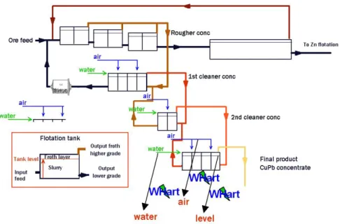
Figure 1.3: A view of the actual solution for the live demonstration The future goal is to apply the same integration process using WirelessHART as wireless protocol, since it is becoming the de-facto standard protocol for wire-less systems in process industry mostly because, as a standards-based technology, it ensures multi-vendor interoperability of a multitude of field devices in process operations. In the figure 1.4, a future plant with WirelessHART control is shown. Details of each part of the final product together with a description of the development process will be given in the following sections.
1.2 Outline of the thesis
Figure 1.4: The future plant with WirelessHART control
1.2
Outline of the thesis
This thesis report is composed by the following sections:
1.2.1
Chapter 2 - Wired Networks
This work involves not only wireless communication. In fact it provides a sort of bridge connection between a wireless system (WirelessHART network) and a wired system (Controller device via MODBUS/TCP). In this section an overview of wired networks and protocols will be given, paying particular attention to the MODBUS protocol.
1.2.2
Chapter 3 - Wireless Networks
In this section an overview of wireless networks and the most wide-spread wireless protocols will be given, with special focus on the WirelessHART technology, which represents a central issue for the thesis work.
1.2 Outline of the thesis
1.2.3
Chapter 4 - Involved ABB’s Industrial IT Devices
The 800xA System is a primary component of the final system. This section aims to give an overview on this component in order to facilitate the understanding of its role in the process.
The final system will have to be able to facilitate the business management by providing communication between the control system itself and the business man-agement systems through the BB’s Industrial IT cpmPlus Enterprise Connectivity (ECS). In this section an overview on the ECS framework will be given, focusing on the features that have been used for our purposes.
1.2.4
Chapter 5 - Integrating the Plant
In this section the entire development process of the final product will be described in details. Starting from the specification of functional and extra-functional re-quirements and the tools selection, we will go through the actual development of the communication manager application. Explanation on how the application is intended to fulfil the specified requirements will be also given.
1.2.5
Chapter 6 - Integrating the Management
The final live demonstration scenario will be presented from the point of view of both the plant operator (through the ABB’s 800xA System) and the enterprise business manager (through the ECS Web Service Integration).
Chapter 2
Wired Networks
Before the advent of the wireless technology, computer networks [4] for industrial automation were built exclusively by using wired technologies. Fieldbus systems represent the most important communication systems used in commercial control installations. At the same time Ethernet, developed by Xerox PARC in 1975, represents a family of the most widespread computer networking technologies for Local Area Networks (LANs) within the office domain, standardized as IEEE 802.3 [5]. Due to its fast spread and consequent components low cost, in the last years there has been a noteworthy economic interest to widely introduce the Ethernet in computer networks for industrial automation. The most known industrial computer network protocols are:
∙ Fieldbus Foundation - it is a family of industrial computer network protocols particularly suited for real-time distributed control systems. It is widely used to establish connections between instruments in manufactory plants [6].
∙ PROFINET - it is an open standard for industrial Ethernet mostly used for industrial automation applications [7].
∙ MODBUS - it is a family of industrial multidrop network based communi-cation protocol to be used over a master/slave communicommuni-cation architecture [8].
2.1 Fieldbus Foundation ∙ Ethernet Industrial Protocol (EtherNet/IP) - it is an open industrial com-munication protocol designed for industrial process control and other au-tomation applications [9].
∙ DeviceNet - it is an industrial communication protocol developed for the interconnection of control devices in industrial automation applications [10]. ∙ CANopen - it is a communication protocol for embedded systems in indus-trial automation environments. It provides different kinds of communica-tion: master/slave, producer/consumer and client/server [11].
In the next sections a description of these three industrial computer network protocols will be given, focusing particularly on the MODBUS, which will be used for our purposes.
2.1
Fieldbus Foundation
Fieldbus Foundation represents a family protocols particularly suited for real-time distributed control in industrial networks. An example of its use might be the connection of instruments in a manufacturing plant. Fieldbus Foundation is not chained to any particular network structure since it can operate on star, ring, branch, tree and daisy-chain topologies. Several versions of Fieldbus Foundation have been released, but in this section we will focus on the Fieldbus Foundation H1. It makes use of both twisted pair and fiber media to allow the communication between multiple devices and the controller, which can communicate with up-to 32 devices just by having a single communication point. This is one of the best improvements over the standard 4-20 mA communication that needed a communication point for each device. It supports several communication methods such as client/server, event based, scheduled/unscheduled, publisher/subscriber. Besides the improvements, Fieldbus Foundation has disadvantages compared to the older 4-20 mA analog signal standard: complexity, cost, speed and devices compatibility.
2.2 PROFINET
2.2
PROFINET
PROFINET is an open standard for industrial Ethernet developed by PROFIBUS-PROFINET International for automation. The standard is composed by two different perspectives:
∙ PROFINET CBA - it is particularly suitable for both component-based communication via TCP/IP and real-time communication in modular sys-tems. The PROFINET CBA idea is that a whole automation system can be almost always divided into smaller autonomous sub-systems.
∙ PROFINET IO - it implements the interfacing with the peripherals by defining the entire data exchange between controllers, which act as masters, and devices, which can be seen as slaves. It follows the provider-consumer model and represents a good solution for fast data exchange between field devices over a WLAN. A typical PROFINET IO system is composed by three devices:
– IO Controller: it is responsible for all the control issues regarding the system
– IO Device: it is a field device that operates under the control of the Controller
– IO Supervisor: it is responsible for setting parameters and diagnosing IO Devices
In PROFINET IO systems, both data and alarms are trasmitted always in a real-time fashion.
PROFINET CBA and IO can communicate on the same bus at the same time and they can operate either separately or combined. The main advantages of PROFINET is its continuous further development that gives the users a long-term perspective for their PROFINET implementations, and the high degree of availability given by the PROFINET CBA autonomous subsystems.
2.3 MODBUS
2.3
MODBUS
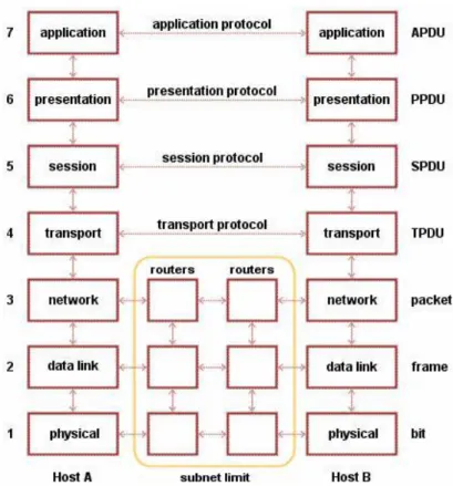
The Open Systems Interconnection reference model, well-known as OSI model, is an abstraction for layered communication. It basically divides the network architecture into seven different layers (fig. 2.1), numbered from top to bottom:
∙ 7 - Application Layer : it handles all the application management tasks by providing network services to the final user and defining interfaces used by the user processes for communicating in the network. Here is where the MODBUS communication protocol is placed.
∙ 6 - Presentation Layer : it provides data conversion from the user’s repre-sentation to the canonical and vice versa.
∙ 5 - Session Layer : it drives the formatting of data to be exchanged over the connection.
∙ 4 - Transport Layer : it is the last abstract layer that acts as interface be-tween the higher levels and the last three representing the physical network. ∙ 3 - Network Layer : it is responsible for all the issues regarding the actual communication from source to destination. It handles any problem related to the interconnection of heterogeneous networks.
∙ 2 - Data Link Layer : it checks the correctness of a bit sequence exchange between two nodes and requests for retransmission in case of transmission corruptions.
∙ 1 - Physical Layer : it handles all the details about the physical connection between the nodes.
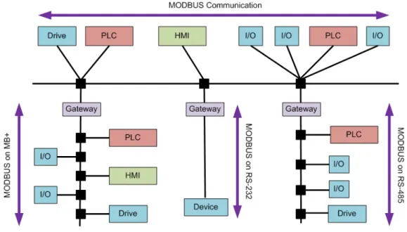
A layer can be viewed as a set of conceptually similar functions providing a number of services to the layer above it and receiving other services from the layer below it. MODBUS is a messaging protocol positioned at level 7 of the OSI model, the application layer. Its main goal is to allow client/server communica-tion between devices which use different types of buses or that are connected to different networks. It was developed in the 1979 by PLC manufacturer Modicon,
2.3 MODBUS
2.3 MODBUS now part of Schneider Electric’s Telemecanique. The MODBUS communication interface released by Modicon was intended as a multidrop network based commu-nication over a master/slave architecture (fig. 2.2). The actual commucommu-nication between MODBUS devices was achieved by using messages whose structure was released as an open standard. The first versions of the MODBUS interface ran on the RS-232 serial communication interface for computers and devices. Due to the needs of longer distances and higher speeds of communication, the RS-232 was later replaced by the RS-485, which also provided the possibility of a real multi-drop network.
Figure 2.2: An example of a MODBUS network architecture
The MODBUS protocol soon became a de-facto standard for industrial net-works thanks to its goodness, flexibility and simplicity. These characteristics encouraged a huge number of vendors to implement the MODBUS messaging system on their devices. Initially, MODBUS was mainly intended for wired serial communication liens, but it has evolved and been extended in order to sup-port wireless communication and TCP/IP networks, which has been used in this project.
2.3 MODBUS
2.3.1
Protocol description
The MODBUS communication interface is based on messages whose format does not depend on the chosen physical interface. A MODBUS device can communi-cate with several devices at once, even if their interfaces differ from each other. On simple serial communication physical interfaces like RS-232 and RS-485, the messages are exchanged in a plain form over the network that is dedicated to the MODBUS communication. In the case that the communication involves more complex network systems, such as TCP/IP over Ethernet, the messages are em-bedded in packets following the format requested by the physical interface. This is the case in which MODBUS and other different connections can share the same physical interface, which is no more dedicated to the single MODBUS. Embed-ded or plain, the MODBUS messages have always the same structure which is composed by four basic elements:
∙ Device address - It specifies the address of the receiver ∙ Function code - It defines the message type:
– 01 - Read coil status: a coil is a discrete output value and this function can be used to read the status of such an output
– 02 - Read input status: input values are read in the same way as the status of coils, but using this function instead
– 03 - Read holding registers: holding registers are used to store internal values of a device. This function allows to read one or more holding register values from a specified slave
– 04 - Read input registers: input registers are read-only values which can be read through this function
– 05 - Force single coil : a coil value can be either read or written. This function is used to force the value of a single coil
– 06 - Preset single register : an holding register value can be either read or written. This function is used to write the value of an holding register
2.3 MODBUS – 07 - Read exception status: it can be used to request the exception
status of a slave device
– 15 - Force multiple coils: as the function 05, it forces coil values, but it’s used to operate on multiple coils at the same time
– 16 - Preset multiple registers: as the function 06, it presets holding register values, but it’s used to operate on multiple holding registers at the same time
– 17 - Report slave ID : it is used to retrieve the ID of a selected slave device
∙ Data - It represents a data block with some additional information
∙ Error check - It is a CRC-32 error check code which results in an infinites-imal chance of undetected corruption to a request or response message Function Code and Data compose the Protocol Data Unit (PDU, fig. 2.3), that together with the Device Address and the Error Check compose the Application Data Unit (ADU, fig. 2.3).
Figure 2.3: MODBUS frame composition
A MODBUS communication session is always started by the master device which sends a message to a specified listening slave device that performs the requested operation and answers to it. Since there can be more devices in the same network, the address in the message header defines the one who should respond to it so that it can be ignored by the others. The MODBUS protocol defines a simple PDU which is kept independent from the underlying communication
2.3 MODBUS layers. The information, about the specific network on which the MODBUS protocol has to be mapped, can be given by additional fields on the ADU. The master device, initiating a MODBUS communication session, builds an ADU that establishes the format of the request. The function code element tells the slave device what kind of operation has to be performed in order to satisfy the request; sub-function codes can be used for defining multiple actions. The data element contains information to be used to perform the operation specified by the function code. While the function code element must be not empty, the data element can be nonexistent for certain requests. The slave device performs the operation specified by the function code in the request’s ADU, and it uses the same value to indicate either an error-free response, by sending back the original function code value, or an erroneous one, by sending back a code equivalent to the original function code but turning its most significant bit to logic 1.
2.3.2
Data model
As every other communication protocol, also the MODBUS has its own data model. It is basically composed by a set of tables with different characteristics. We will consider only the four tables of our interest, which are:
∙ Discrete input - it is a single bit read-only type that can be provided by an I/O system.
∙ Coil - it is a single bit read-write type that can be alterable by an application program.
∙ Input register - it is a 16-bit read-only word that can be provided by an I/O system.
∙ Holding register - it is a 16-bit read-write word that can be alterable by an application program.
The four tables can be viewed as one overlaying each other since the differ-ence between inputs and outputs, as well as between bit-addressable and word-addressable, does not imply any additional application behavior. All the data handled via MODBUS has to be located in the device application memory, but it
2.3 MODBUS does not mean that the physical address memory has to match the data reference; the only constraint to be satisfied is that data reference has to be linked with the actual physical address. MODBUS uses unsigned integer starting at zero as logical reference numbers.
2.3.3
A MODBUS library in C: libmodbus
libmodbus is a shared library written in C and specifically developed, under LGPL license version 3, for GNU/Linux and MacOSX. It provides functionalities that allow the development of both slave and master applications in respect to the MODBUS protocol established by Modicon. It allows to implement both RTU and TCP communication, and provides all the MODBUS functions. Moreover, it gives structures for the storage and manipulation of data in respect to the MODBUS data model.
Chapter 3
Wireless Networks
The thesis work aims to integrate wireless systems into process industry and business management. This chapter gives an overview of wireless communication and the most common protocols used for wireless communication.
3.1
Wireless Communication
Wireless communication [12] is intended as a transfer of information over a vari-able distance without wires. It can be performed via radio frequency, short-range and long-range microwave, and short-range infrared communications.
The first applications of the wireless communication were implemented by the Croatian scientist Nikola Tesla (1894) who continued the work started by David E. Hughes (1878) and later by Heinrich Rudolf Hertz (1888) regarding the theory of electromagnetic waves.
3.2
Wireless Common Protocols
Since the wireless communication is becoming more and more widespread, many protocols have been developed. This section will give a general overview of the most used wireless protocols and focus on the WirelessHART protocol, which constitutes a primary issue for the thesis work.
3.2 Wireless Common Protocols
3.2.1
The IEEE 802
The IEEE 802 is a family of standards related to Local Area Networks (LAN) and Metropolitan Area Networks (MAN). It is maintained by the IEEE 802 LAN/MAN Standards Commitee, which is divided into several teams handling several sub-families of standards. In the following sections a description of the 802.11 [13] and 802.15 sub-families will be given.
3.2.1.1 The IEEE 802.11
The IEEE 802.11 represents a family of standards created by the IEEE LAN/MAN Standards Committee in order to carry out Wireless Local Area Network (WLAN) computer communication using the 2.4, 3.6 and 5 GHz frequency bands. The 802.11 family is composed by the following standards:
∙ 802.11-1997 - it was the first wireless networking standard which was re-leased in 1997. It introduced network bit rates of 1-2 Mbit/s and three dif-ferent physical layer technologies: 1 Mbit/s infrared, 1-2 Mbit/s frequency-hopping spread spectrum and 1-2 Mbit/s direct-sequence spread spectrum (DSSS). A great innovation brought by this standard was the use of 2.4 GHz in microwave transmissions, while the previous WLAN technologies used much lower ones (e.g. US 900 MHz).
∙ 802.11a-1999 - it improves the original standard by the use of a 52-sub carrier Orthogonal Frequency-Division Multiplexing (OFDM) as physical layer, with a maximum raw data rate of 54 Mbit/s. Moreover it uses the 5 GHz band for microwave transmissions, which gives a significant advantage considering the 2.4 GHz band overloading.
∙ 802.11b-1999 - it is much similar to the original standard, but much more used since, even though it has same modulation (DSSS) and frequency (2.4 GHz), it grants a maximum network bit rate of 11 Mbit/s instead of 2 Mbit/s. 800.11b devices use to suffer interferences from other products that operate in the 2.4 GHz band like microwave ovens, cordless telephones and Bluetooth devices.
3.2 Wireless Common Protocols ∙ 802.11g-2003 - it is an evolution of the 800.11b standard. Using the same 2.4 GHz band, it grants a maximum network bit rate of 54 Mbit/s thanks to its OFDM modulation scheme (same as 802.11a). Its hardware is yet full compatible with 802.11b, even though the overall speed of a 802.11g network would be reduced in presence of a 802.11b device.
∙ 802.11n - it is a proposed evolution of the 802.11 standard not yet delivered, which aims to significantly improve the maximum network bit rate from 54 Mbit/s (802.11a/g) to 600 Mbit/s. The biggest innovation would be the use of a Multiple-Input Multiple-Output (MIMO) physical layer that implies the use of multiple transmitter and receiver antennas in order to improve the network speed. The 802.11n standard is intended to ensure compatibility with legacy 802.11 devices.
3.2.1.2 The IEEE 802.15
The IEEE 802.15 represents a family of standards created by the IEEE LAN/MAN Standards Committee and specialized in Wireless Personal Area Networks (WPANs). The 802.15 family main standards are the 802.15.1-2002 and 802.15.4-2003 on which underlie respectively the Bluetooth and the ZigBee technologies that will be described in the following sections.
3.2.2
Bluetooth
Bluetooth [14] is a short-range wireless networking technology particularly suited for Wireless Personal Area Networks (WPAN) and based on the IEEE 802.15.1-2002. It is a protocol for exchanging information from both fixed and mobile de-vices over a short distance. The word Bluetooth comes from the Danish Bl˚atand, which was the name of the tenth-century king Harald I of Denmark and Nor-way. As well as Harald I united the Scandinavian tribes into a single kingdom, the Bluetooth technology is intended to unite different communication proto-cols, making one single standard. All Bluetooth devices operates in the 2.4 GHz band and the protocol provides a maximum network bit rate of 3 Mbit/s, even though Alliance technologies has proposed the WiMedia, which could be capable of providing a maximum bit rate of 480 Mbit/s.
3.3 WirelessHART
3.2.3
ZigBee
ZigBee [15] is a set of high-level communication protocols based on the IEEE 802.15.4-2003 standard, suited for low data rate WPANs. It aims to provide a simpler and less expensive specification than other existent WPANs (e.g. Blue-tooth). ZigBee operates in the industrial, medical and scientific radio bands. Typical application areas include home entertainment and control, mobile ser-vices, commercial building and, as in our case, industrial plant management. The standard specifies the physical, MAC and data link protocol layers. Con-cerning the physical layer, ZigBee uses direct-sequence spread spectrum (DSSS) like some standards of the IEEE 802.11 family. ZigBee has been developed to add mesh networking to the IEEE 802.15.4-2003. It is particularly suited for embedded systems where reliability and versatility are more important than the bandwidth.
3.2.4
WiMax
Worlwide interoperability for Microwave Access (WiMAX) [16] represents a telecom-munication technology based on the IEEE 802.16 family standards. Its final re-lease operates in the 10-66 GHz band range, but it still supports the 2-11 GHz. The physical layer also differs from the 802.16 family since WiMAX uses a Scal-able OFDMA (SOFDMA) instead of the normal OFDMA. WiMAX provides a maximum network rate bit of 3 Mbit/s and is particularly suited for connectiong Wi-Fi hotsposts to Internet and provides a wireless stable alternative to cable broadband access.
3.3
WirelessHART
The HART Communication foundation (HCF) released the new HART 7 speci-fication on September 2007. HART is a master/slave protocol which means that a field (slave) device only acts when called by a master. The HART protocol can be used in various modes for communicating information to/from smart field instruments and central control or monitoring systems. The HART 7 specifica-tion includes WirelessHART [17], the first open wireless communicaspecifica-tion standard
3.3 WirelessHART designed specifically for industrial environments in which plant applications need reliable, secure and simple wireless communication. The protocol gets its power from reliability and simplicity of installation and maintainance of its architecture, compared to legacy star-connected systems. WirelessHART supports also legacy HART devices by the use of WirelessHART adapters. We selected WirelessHART as wireless protocol for our purposes since devices at Boliden Plant are HART devices, easily connectible to a WirelessHART network by using the previously mentioned adapters. This is not the only reason. In fact WirelessHART has been designed to meet the unique requirements of wireless networks operating in process plants through the following key capabilities:
∙ Reliability even in presence of interference, thanks to mesh networking, channel hopping and time-synchronized messaging.
∙ Security and privacy for network communications through encryption, au-thentication, verification, key management and other open industry-standard best practices.
∙ Effective power management through Smart Data Publishing and other techniques that make low-power options practical for wireless devices.
3.3.1
The WirelessHART Architecture
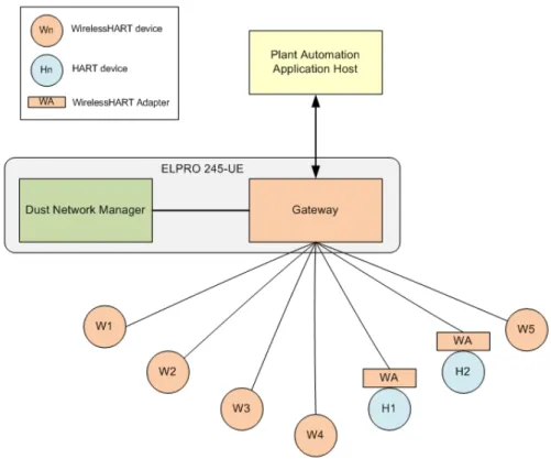
A WirelessHART network (fig. 3.1) consists of:
∙ WirelessHART network manager - it is an application responsible for the management of the network and the connected devices. It creates the net-work, allows new devices to connect to it, sets the communication schedule for them and monitors every happening in the network. It does not have to reside in the actual plant network, but rather on a gateway device or on other systems device.
∙ WirelessHART field devices - a field device can be:
– Router device: it is used to improve network coverage and extension by forwarding messages from/to other network devices
3.3 WirelessHART – Process connected instrument : it typically represents a measuring or positioning device used for process monitoring and control. As well as the router device, it is also capable of forwarding messages from other network devices
– WirelessHART Adapter : it allows a HART instrument without wire-less capability to be connected to a Wirewire-lessHART network.
∙ WirelessHART gateway - it allows the exchange of data between the mesh network and a plant automation network. It is responsible for providing the access to the WirelessHart devices by a host application or system.
Figure 3.1: A WirelessHART Network
The communications pass always through the gateway that routes the packets to the specified destination using standard HART commands. The plant automa-tion applicaautoma-tion host might be a TCP network, a remote I/O system or a specific
3.3 WirelessHART bus. The WirelessHART network ensures correct order in transmissions by the MAC protocol, which specifies the communication scheduling for the devices.
3.3.2
The WirelessHART Network
The WirelessHART network can be built following several different topologies in order to be able to support a large variety of application requirements. The following three topologies (fig. 3.2) are, however, the most used:
∙ Star - this type of network is widely used for small applications and it contains only one router device which communicates with the other end devices.
∙ Mesh - in this type of network, all the field devices are router devices. This provides a robust network with redundant data paths which facilitate fast adaptation of the network to changes of the environment.
∙ Mixed Star/Mesh - it is a combination of the star and mesh topologies and consequently it will be composed by multiple sets of router devices and end devices.
3.3 WirelessHART One of the noteworthiest attributes of a WirelessHART network is its self-organizing ability, which is carried out through three network formation steps: advertising, joining and scheduling. A new network starts with the gateway device sending advertising packets which announce the presence of the network. The packets include time synchrionization information and a network unique ID which has to be matched by the devices trying to join the network. After matching the ID, the new device sends a join request packet to the network manager through the node from which it received the advertising packet. The network manager replies by either accepting the device, through sending back an activation packet to the device node, or refusing it. In case of acceptance, the network manager sets up the links between the new device node and the already existing ones. As last step of the network formation process, the network manager requests information from the new device on how often it will need to send data over the network, and creates a communication schedule for the new device and all the involved intermediate routing devices.
3.3.3
The Dust Network Manager
Dust Networks [18] is a company which focuses on design and manufacture of wireless sensor networks for industrial solutions. It was founded in 2002 by Kris Pister, who started the Dust project in 1997 at UC Berkeley, in collaboration with a team of dedicated engineers. Dust Networks’ embedded wireless network-ing products (SmartMesh) provide customers with robust wireless information-gathering systems that give better visibility and control of the connected physi-cal world. These products aim to decrease the customers’ time to market and to give end users complex sensors and robust wireless information-gathering systems that decrease the installation costs and increase the efficiency of the operations. SmartMesh products are considered particularly suited for industrial monitor-ing and control solutions that have specific needs concernmonitor-ing high reliability and flexibility. Within the wide range of SmartMesh products, the IA-500 family of standards-based wireless sensors networking systems has been chosen for our project, due to its compatibility with the WirelessHART standard. These prod-ucts combine the Dust Networks’ robustness together with the industry-leading
3.3 WirelessHART low-power radio technology to provide complete embedded WirelessHART solu-tions. A SmartMesh-enabled network is composed by a network of motes (re-mote sensors), a SmartMesh manager that configures and manages the network and client applications that interact with the network through the manager. The communication between the client application and the SmartMesh manager [19] is based on a mixed XML-RPC/XML protocol.
3.3.3.1 XML-RPC Communication Protocol
XML-RPC [20] is a communication protocol based on XML-encoded remote pro-cedure calls (RPC) over HTTP transport mechanism. It was introduced in con-junction by UserLand Software and Microsoft in 1998. XML-RPC is probably the simplest web service approach and lets the developer to make function calls across networks. The power of this protocol is the combination of three stan-dards, the communication architecture (RPC), the vocabulary (XML), and the transport mechanism (HTTP). XML-RPC is a good way for establishing many types of connection between computers as well as between different devices. In our case it will be used for the interaction between the Dust manager and the communication manager application.
3.3.3.2 XML-RPC Protocol Description
In this section we will go through the XML-RPC protocol in terms of the requests and responses required to invoke computations on a remote device using XML through HTTP. More precisely we will give a description of the XML-RPC library we used to create this kind of connection: xmlrpc-C, which is a programming li-brary for writing XML-RPC servers and clients in C. The RPC architecture on which the protocol is based, implies the presence of two parties: a calling process (client) and a called process (server). The client uses procedures that a server provides at a certain HTTP URL. In our case the Dust Manager will act as server while the communication manager application will act as client invoking procedures that operate on the Dust Network, through the Dust Manager. An XML-RPC message is an HTTP-POST request (fig. 3.3) whose body is
writ-3.3 WirelessHART ten in XML. It contains the name of the invoked method within the XML tag <methodName></methodName>.
Figure 3.3: XML-RPC Request Example
Procedures usually make use of parameters, specified within the XML tag <params></params> that might in some cases be empty. Parameters can be numbers, scalars, strings, dates as well as complex record and list structures; later in the section we will focus on data-types. In the request presented above the parameter is represented as the data type i4 (integer). The procedure invoked by the client is executed on the server which replies with another XML formatted message (fig. 3.4).
Figure 3.4: XML-RPC Response Example
Requests and responses make use of data types in the form of, respectively, parameters and return values. XML-RPC provides a set of simple data types from which more complex data types can be derived. The simple data types, which are always inserted within the XML tag <value></value>, are the followings:
∙ Integer - it represents the standard integer data type and can represent a 32-bit signed integer. It can be represented both using <int>n</int> or
3.3 WirelessHART <i4>n</i4> (Note that the number 4 comes from the length of the integer: 4𝑥8 bits). Only numerals from 0 to 9 and the characters + and −, for signed integers, can be used within the tags; no empty spaces are allowed.
∙ Binary - it is used to represent all those characters prohibited by the XML vocabulary in a base-64 encoding manner. These characters are commonly known as control characters and are the ones with an ordinal value below than the empty space. It is represented by the the binary object, from the encoding defined in RFC 2045 [21], within the tags <base64></base64> ∙ String - it represents ASCII string values. There are two different
nota-tions to represent strings, either by placing the value within the value tags (<value>sTrInG</value>) or by explicitly adding a typed representation of strings through <string>sTrInG</string>.
∙ Boolean - it encodes the boolean logic values and it is represented by the tags <boolean>bool</boolean> where bool can have only two possible values, 0 (false) or 1 (true).
∙ Date-Time - it encodes the date-time type using the ISO 8601 standard. It is represented by an absolute specification of a combined date and time following this pattern:
<dateTime.iso8601>CCYYMMDDTHH:MM:SS</dateTime.iso8601>. Note that there is no indication about the time zone related to the value. The basic types are not sufficient for most of the applications. Simple types can be composed into more complex data structures (e.g. arrays, record-like structures):
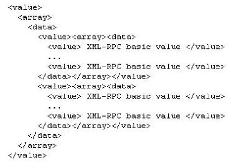
∙ Array - it allows synthesis of data items into an untyped list in order to be able to contain elements of different data types. The array type is represented by the tags: <array><data>...</data></array>, that will contain the basic data type values (fig. 3.5).
3.3 WirelessHART
Figure 3.5: XML-RPC Array Type
A data item may be of any XML-RPC type, basic or composed. It is so possible to represent multidimensional arrays by embedding an array within another (fig. 3.6).
Figure 3.6: XML-RPC Multidimensional Array Type
∙ Struct - this composed type allows encoding of the associative array, known also as dictionary. It is represented by a set of members, each of which is a pair (name, value). The name is represented by an ASCII string, while the value may be represented by whichever XML-RPC data type,
3.3 WirelessHART both basic and composed. The struct type is represented by the tags: <struct></struct>, that will contain the members (fig. 5.3).
Figure 3.7: XML-RPC Struct Type 3.3.3.3 A XML-RPC library in C: xmlrpc-c
xmlrpc-c [22] is a modular implementation of XML-RPC for C and C++, specif-ically designed for Unix platforms, which helps programmers to develop XML-RPC both client and server applications. The function libraries that compose xmlrpc-c let developers write applications able to make XML-RPC calls (client) or execute them (server) at any of the levels of understanding of the XML-RPC protocol. There are two sets of libraries composing xmlrpc-c:
∙ C library
– libxmlrpc: it provides general facilities
– libxmlrpc client : it provides facilities for client implementations in C – libxmlrpc server : it provides facilities for server implementations in C
and that are independent of the transport mechanism
– libxmlrpc server abyss: it provides facilities for Abyss HTTP server implementations in C
3.3 WirelessHART – libxmlrpc server cgi : it provides the facilities for CGI server
implemen-tations in C under an arbitrary HTTP server ∙ C++ library
– libxmlrpc++: it provides general facilities
– libxmlrpc client++: it provides facilities for client implementations in C++
– libxmlrpc server++: it provides facilities for server implementations in C++ and that are independent of the transport mechanism
– libxmlrpc server abyss++: it provides facilities for Abyss HTTP server implementations in C++
– libxmlrpc server cgi++: it provides the facilities for CGI server imple-mentations in C++ under an arbitrary HTTP server
– libxmlrpc server pstream++: it provides facilities for implementing a pseudo-XML-RPC server in C++ that uses a packet stream instead of HTTP and has multi-RPC client/server connections
Chapter 4
Involved ABB’s Industrial IT
Devices
4.1
ABB’s Industrial IT 800xA System
The Industrial IT Automation System 800xA (fig. 4.1) provides the technology and solutions needed to achieve a competitive advantage by enabling a plant to perform in a smarter, better and safer manner with cost savings. It improves plant productivity by the following integrated core functions:
∙ Operations - the Process Portal, an intuitive system interface, provides a consistent method for accessing enterprise data and interacting with multi-ple applications from several different connected workstations, both locally and remotely.
∙ Engineering - the integrated engineering environment completely supports the lifecycle of the automation project, from planning to commissioning and operation, passing through configuration and library management. This support minimizes system ownership costs.
∙ Safety - system functions together with operator and engineering tools re-duce plant risks through an accurate management of the human factor.
4.1 ABB’s Industrial IT 800xA System ∙ Information Management - information management enhances the useful-ness of data by collecting, storing and presenting historical, process and business data from all operations.
∙ Production Management - it provides speed, agility and control needed to respond to increasing production requests by modelling, executing and tracking information associated with the control flow across the plant. ∙ Asset Optimization - asset optimization software assesses and reports
equip-ment conditions in real-time in order to decrease costly corrective mainte-nance and optimize maintemainte-nance and calibration work flows.
∙ Control and I/O - a complete suite of standards-based hardware and soft-ware provides total plant control. Each controller is provided with a full line of industrial I/O interfaces to meet all plant environments.
∙ Device Management - the integration of intelligent field devices via fieldbus standards reduces lifecycle costs through significant cost savings in design, implementation and operation of field equipment.
4.2 ABB’s Industrial IT cpmPlus Enterprise Connectivity
4.2
ABB’s Industrial IT cpmPlus Enterprise
Con-nectivity
The final system will facilitate business management by integrating plant opera-tions handled by the controller device, and a remote enterprise resource planning system (SAP) [23], through the ABB’s Industrial IT cpmPlus Enterprise Con-nectivity (ECS) framework 4.0 [24]. Enterprise Resource Planning (ERP) is a company-wide computer software system used to manage resources, information, and functions of a business from shared data. Integration between plant opera-tions and enterprise business applicaopera-tions can significantly increase productivity, flexibility and quality control. The biggest challenge in this process is dealing with the huge installed base existing in manufacturing today, which has been prohibitive to interface to business management in terms of cost. ECS aims to change this perception by providing a unified framework for managing transac-tional and event-driven systems in a common environment. The ECS framework provides the basic execution functionality and generic connectivity needed to support configuration and servicing of connectors, by the following set of tools:
∙ Process Definition Manager - it provides an environment for process defi-nition and development together with support for data mapping and event handling.
∙ ECS Connectors - it is a collection of ready-to-use enterprise services that provide connectivity to several different types of application:
– Web Services Connectors: it provides integration (fig. 4.2) with en-hanced SOA applications.
– Database Connector: it provides connectivity to RDBMS databases. – OPC Connector: it gives the possibility to connect real-time
applica-tions directly to business systems.
– TCP/IP Connector: it provides integration with every TCP/IP based application.
4.2 ABB’s Industrial IT cpmPlus Enterprise Connectivity – XML Connector: it allows processing of an XML structure defined by
a given XML schema.
Figure 4.2: ECS Web Service Connectivity
The ECS framework is particularly suited for developing vertical integration solutions between enterprise business management and manifacturing processes. In order to configure the different aspects of a particular integration process, the ECS framework provides a set of tools:
∙ Process Defition Tool - it allows to model a given process using ISA 95 object models [25]. It uses various connectivity adapters that help to automatically build ISA 95 representation of data structures from several different external systems.
∙ Report Manager - it generates reports about the process state and history of changes based on the data stored in the ECS database.
∙ ECS GUI Modeling Tool - it provides functionalities that help in building slim HTML user interfaces, helpful from the final user perspective.
The final product will make use of the ECS framework connectivity in order to share information between the 800xA System and the enterprise business layer
4.2 ABB’s Industrial IT cpmPlus Enterprise Connectivity (SAP). The ECS Process Definition Tool will be used for this purpose. A special Control System plug-in will allow us to import the entire equipment definition from the control layer in the 800xA to the ECS Process Definition Tool. The Pro-cess Definition Tool provides also the possibility to check the model correctness by detecting any syntax or inconsistent object naming and definition errors. The created model is saved as a plain XML file so that it can be managed in several ways. After checking the correctness, the tool gives the possibility to generate an 800xA executable code out of the model and to deploy it directly on th 800xA system. After the deployment, it gives to the business management layer the possibility to interact with the executing model through the ECS Web Service Integration.
Chapter 5
Integrating the Plant
In this section we will describe the actual development and setting up of the final product. As mentioned before, the final product is a system which handles the exchange of information between a Wireless HART network and a controller device (ABB’s 800xA System) through a communication manager application. In the following sections the development process concerning the communication manager application will be given in details from the early stages of requirements specification to the actual implementation. The final step of the process is a live demonstration of the whole system execution at the Boliden Mining Plant. The SOCRADES project’s constraints turned the choice of wireless protocol to Zigbee instead of WirelessHART for the live demonstration. This led to a slightly differ-ent scenario from the ideal solution, which uses Zigbee as wireless protocol and a differend communication manager application developed by another member of the project. The future objective is applying the ideal solution to a similar industrial scenario using WirelessHART as wireless protocol and the communi-cation manager applicommuni-cation described in this work as wired/wireless interaction manager.
5.1 Development Process of the Communication Manager Application
5.1
Development Process of the Communication
Manager Application
A development process has to be carried out by following a suited model. In the specific case of the communication manager application, a V-Model (fig. 5.1) has been taken as guide for the development process. The V-Model is an extension of the well-known Waterfall Model. Its main attribute is the strong relationship be-tween development life-cycle phases and the related testing phases. Testing starts from the first phases of the development, helping the developers to take better decisions in order to minimize problems during the final implementation/coding phase, where different design choices could make the difference in terms of time to market and costs. Generally solving problems in the design phases is faster and cheaper than in the implementation phase.
5.2 Requirements Specification
5.2
Requirements Specification
In this section we will go through the requirements specification, which is intended to be a comprehensive description of the aimed purposes for the application under development. It describes in details what the application must be able to do and how it is expected to perform. The requirements specification phase aims to minimize time, effort and cost required by the development process to achieve desired goals. The section is divided into functional requirements specification and extra-functional requirements specification.
5.2.1
Functional Requirements
The functional requirements specification is a formal documentation that we will use to describe the application’s intended capabilities, from a pure behavioral point of view. It will explain what the application is intended to be able to do and how different components are supposed to interact with each other.
∙ F1 - Client side in the WirelessHART network: the application will have to be able to act as client in a WirelessHART Network by interacting with the Dust Network Manager.
– F1.1: Connect to the WirelessHART network through the Dust man-ager. The application has to be able to create, manage and close a connection to the WirelessHART network by interacting with the Dust manager.
– F1.2: Send read requests to the Dust manager. The application must be able to send requests to the Dust manager asking for information about network and connected motes.
– F1.3: Send write requests to the Dust manager. The application must be able to send requests to the Dust manager asking for changings of information regarding network and connected motes.
– F1.4: Receive replies from the Dust manager. The application must be able to receive replies from the Dust manager during both the connection phase and the interaction with the network (read requests).
5.2 Requirements Specification – F1.5: Listen for events from the Dust manager. After completing the connection phase, the application must start listening for events coming from the network through the Dust manager. It must be con-tinuously listening until the connection to the network is closed. – F1.6: Handle events received from the Dust manager. Whenever an
event from the network reaches the application side, it must be handled by the application itself in a proper way. This operation might imply operations to be performed by the MODBUS slave side of the applica-tion (see F3 - Interacapplica-tion between the Dust client and the MODBUS slave).
– F1.7: Handle Dust communication errors. The application must be able to handle communication errors since the early connection phase. – F1.8: Polling requests about the network configuration. The applica-tion must be able to keep always updated informaapplica-tion about the status of the devices connected to the network by polling requests about the network configuration to the Dust manager.
– F1.9: Keep reliable information about the devices. The application must keep reliable information in the shared memory about the devices connected to the network.
∙ F2 - MODBUS slave interacting with the 800xA System (MOD-BUS master): the application will have to be able to act as slave in a MODBUS connection to the 800xA System, which will act as master.
– F2.1: Listen for incoming connection requests from the MODBUS master device. Once started and connected to the Dust Network, the application must start listening for incoming connection requests from the MODBUS master device.
– F2.2: Handle connection requests from the MODBUS master device. Whenever it receives a connection request from a MODBUS master device, the application must be able to grant the permissions and create the actual connection.
5.2 Requirements Specification – F2.3: Listen for requests from the connected master device. Once the connection between the application and the MODBUS master device has been correctly established, the application must start listening for requests from the MODBUS master device.
– F2.4: Handle read requests from the connected master device. The MODBUS master device may send read requests (e.g. polling read re-quests) to the application, which has to be able to access the MODBUS data memory slot and return the right values.
– F2.5: Handle write requests from the connected master device. The MODBUS master device may send write requests to the application, which has to be able to access the MODBUS data memory slot and perform the requested operation on it.
– F2.6: Handle MODBUS communication errors. The application must be able to handle communication errors since the early connection phase.
∙ F3 - Interaction between the Dust client and the MODBUS slave: the application will have to be able to perform MODBUS operations while handling Dust events and polling configuration requests.
– F3.1: Listen concurrently for MODBUS requests and Dust events. The application must be able to concurrently listen for and handle MOD-BUS and Dust requests while polling network configuration requests. – F3.2: Update MODBUS stored data in response to Dust events. Events
received from the Dust manager might imply a modification in the MODBUS data. The application must be able to perform MODBUS data manipulation even during the handling of Dust events.
– F3.3: Ask for updating in the Wireless network in response to MOD-BUS write requests. MODMOD-BUS write requests from the MODMOD-BUS mas-ter device might imply a modification in the Wireless network. The application must be able to ask for network, or motes, modification required after MODBUS data changes.
5.2 Requirements Specification – F3.4: Initialize the MODBUS data memory slot. Once the applica-tion establishes a connecapplica-tion to both Wireless network and MODBUS master, it must be able to initialize the MODBUS data memory slot using the information received from the Dust network configuration. – F3.5: Handle the MODBUS data memory slot. The application must
be able to read/write MODBUS data from a memory slot which will be shared between read and write functions.
– F3.6: Handle access rights to the MODBUS data memory slot. Since the access to the MODBUS data memory slot could be requested by several functions at the same time, the application must be able to manage the access rights.
∙ F4 - XML handling: the application must be able to handle XML doc-uments.
– F4.1: Parse an XML document. The application must be able to parse and generally handle XML documents since Dust communication is based on a mix XML-RPC/XML protocol.
– F4.2: Recognize Dust notifications. While parsing the XML document, the application must be able to distinguish between event and data notifications from the Wireless network in order to perform the right operations in response to them.
5.2.2
Extra-Functional Requirements
The extra-functional requirements specification is a formal documentation that we will use to describe in details the intended quality attributes of the application under development.
∙ R1: Reliability of data in the shared memory. A reply to every request regarding the network configuration must be received at latest within 1 second, otherwise the data stored in the shared memory cannot be trusted and be available. The system achieves this requirements using an alarming system that is shown in the behavioral design section (fig. 5.11)
5.3 Design Specification ∙ R2: Shared memory race-conditions-free access. The right to be accessed must be granted at one function at time in order to avoid race-conditions. It is achieved by the system through a mutex lock system on the shared memory that must be used by every function which asks to access the shared memory: if a function is accessing the memory, then it is locked and can not be accessed by another function until the lock is released.
5.3
Design Specification
After the completion of the requirements specification phase, the development process continues with the design of the application from both its structural and behavioral perspective. The first step is to create a conceptual design model, which will be the basis for the detailed structural and behavioral models.
5.3.1
Conceptual Design
The conceptual design phase aims to build a model (fig. 5.2) of the application under development, from a conceptual, non-detailed point-of-view. This means that it will show which are the application’s main components and how they interact both with each other and with the external world. Since the model represents simply an idea about the application structure, no formal languages have been used to build it.
5.3 Design Specification Looking at the model, the following elements can be identified:
∙ Communication Manager Application - this element represents the actual application under development and it can be considered a bridge be-tween the 800xA System and the WirelessHART network. The application is composed by the following components:
– MODBUS Slave Unit : this set of variables and functions will compose the MODBUS slave unit that will act as slave in the MODBUS/TCP master/slave connection to the 800xA System (master device).
– Dust Client Unit : this set of variables and functions will compose the Dust client unit that will act as client in the server/client connection to the WirelessHART network, through the Dust Manager (server). – MODBUS Data Shared Memory: this set of variables and functions
will handle all the issues concerning the shared memory slot for the storage of MODBUS data. It will be used for read/write requests by the MODBUS master (e.g. 800xA System) as well as for the updating operations derived by modifications at the WirelessHART network. – XML Manager : this set of variables and functions will manage the
XML documents used for the communication between the application and the Dust Manager.
∙ 800xA System - this element represents the MODBUS master device that will be connected to the slave application under development.
∙ WirelessHART Gateway/Dust Manager - this element represents the Dust Manager that will act as server in the server/client connection between the WirelessHART network and the application under development.
5.3.2
Structural Design
Driven by the conceptual model of the application, a more accurate and detailed design phase was carried out: structural and behavioral design using UML as
5.3 Design Specification modeling language. In this section the structural design will be described in de-tails together with the derived UML design model (fig. 5.3). The communication manager application system is composed by the following components:
Figure 5.3: Structural model in UML
∙ MODBUS Slave Thread - The MODBUS slave unit has been thought as a thread in order to be able to perform operations at the same time as the Dust client unit. This design element represents the set of functions and variables that will compose the MODBUS slave thread, responsible for the communication with the MODBUS master devices. It directly inter-acts with the Connections Handler, which handles the connections, and the Shared Memory Handler, which handles the MODBUS data in the shared memory slot.
∙ Dust Client Thread - As well as the MODBUS slave unit, also the Dust client unit has been thought as a thread in order to be able to perform its
5.3 Design Specification operations in parallel with the MODBUS slave unit. The Dust client thread gives birth to two different threads:
– Polling Thread: it is in charge of polling requests to the Dust manager regarding the information about the devices connected to the network in order to have it always updated and reliable in the shared memoery. – Notification Thread: it is in charge of all the other operations
con-cerning the WirelessHART network management.
∙ Connections Handler - this element represents the set of functions and variables that handles the two connections: via MODBUS and via Dust. ∙ Shared Memory Handler - it is composed by a set of variables and functions
that are in charge of managing the shared memory slot for MODBUS data about the WirelessHART network.
∙ XML Manager - it is the set of variables and functions that parses and tokenizes the XML documents in order to extract specific tags and values.
5.3.3
Behavioral Design
The natural step after the structural design phase is the behavioral design phase that is driven by the requirements specification previously described. In this phase the expected behavior of the application is formally modelled by using UML sequence diagrams and following what expressed in the requirements specification. Each modelled feature will be mapped on the related functional requirements. The behavioral design phase led to the creation of the following UML sequence diagrams:
∙ Start Application - this diagram shows the steps performed by the ap-plication when it gets started (fig.5.4). The user launches the apap-plication which, through the Connections Handler module, connects to the Wire-lessHART network by the Dust client thread and asks for the configuration of the network in terms of connected motes. The information received by the network will be processed by the XML Manager functions and given back to
5.3 Design Specification the Connections Handler module which stores it in the shared memory slot properly initialized. After the completion of this operation, the Connection Handler module passes the control to the Dust Client and MODBUS Slave threads which will continue the execution. The functional requirements mapped on this behavioral model are: F3.4, F3.5, F3.6, and F4.1.
Figure 5.4: Start application sequence diagram
∙ MODBUS Slave initialization - When the application have been started and the shared memory initialized, the control passes to the MODBUS Slave and the Dust Client threads. This diagram shows how the MODBUS Slave Thread is initialized in order to start its execution (fig. 5.5). The Connec-tions Handler module gives the control to the MODBUS Slave Thread which starts listening for incoming connection requests from MODBUS master de-vices. When a request arrives, it handles it by either accepting or refusing it. In case of acceptance, it establishes a connection to the MODBUS mas-ter device and starts to listen for incoming queries from it. The functional requirements mapped on this behavioral model are: F2.1, F2.2, F2.3, F2.6 and F3.1.