School of Innovation, Design and Engineering
Mälardalen University, Academy for Innovation, Design and Engineering Presentation day: June 7th, 2019
Supervisor, company: Fredric Tholence & Eric Johansson Supervisor, university: Bengt Gustafsson
Examiner: Sten Grahn
ABB Corporate Research Center
Ultra light-weight
design through
Additive
Manufacturing
Master thesis work
Advanced level, 30 credits
Product and process development
Barrett Sauter
ABSTRACT
ABB Corporate Research was looking to redevelop one product to be manufactured via polymer additive manufacturing (AM), as opposed to its previously traditionally manufacturing method. The current product is cylindrical in shape and must withstand a certain amount of hydrostatic pressure. Due to the pressure and the current design, the cannister is prone to buckling failure. The cannister is currently produced from two cylindrical tube parts and two spherical end sections produced from solid blocks of the same material. For assembly, an inner assembly is inserted into one of the tube parts and then all parts are welded together. This product is also custom dimensioned for each purchase order. The purpose of investigating this redevelopment for AM is to analyse if an updated inner design unique to additive manufacturing is able to increase the performance of the product by increasing the pressure it can withstand from both a material failure standpoint and a buckling failure. The redevelopment also aims to see if the component count and process count can be decreased. Ultimately, two product solutions are suggested, one for low pressure ranges constructed in ABS and one for high pressure ranges constructed in Ultem 1010.
To accomplish this, relevant literature was referred to gain insight into how to reinforce cylindrical shell structures against buckling. Design aspects unique to AM were also explored. Iterations of these two areas were designed and analysed, which led to a final design choice being decided upon. The final design is ultimately based on the theory of strengthening cylindrical structures against buckling through the use of ring stiffeners while also incorporating AM unique design aspects in the form of hollow network structures. By utilizing finite element analysis, the design was further developed until it held the pressure required. Simulation results suggest that the ABS product can withstand 3 times higher pressure than the original design while being protected against failure due to buckling. The Ultem simulation results suggest that the product can withstand 12 times higher pressure than the current design while also being protected against failure due to buckling. Part count and manufacturing processes are also found to have decreased by half.
Post-processing treatments were also explored, such as the performance of sealants under pressure and the effects of sealants on material mechanical properties. Results show that one sealant in particular, an acrylic spray, is most suitable to sealing the ABS product. It withstood a pressure of 8 bar during tests. The flexural tests showed that the sealant did indeed increase certain mechanical properties, the yield strength, however did not affect the flexural modulus significantly.
This work gives a clear indication that the performance of this product is feasibly increased significantly from redeveloping it specifically to AM.
(Keywords:) additive manufacturing, AM, fused deposition modeling, FDM, polymer, buckling, post-processing treatments
ACKNOWLEDGEMENTS
I would like to thank everyone who supported me in this endeavour. First and foremost, I would like to thank my university supervisor, Bengt Gustafsson, not only for the help in simulations and manufacturing test equipment, but for being a source of strength and encouragement in certain times. I would like to thank my supervisors from ABB CRC, Fredric Tholence, Eric Johansson and Saeed Maleksaeedi. You gave me direction and further insight into areas which were interesting to explore and what was expected from this work. I would like to thank Fredrik Finnberg and Digital Mechanics for advising on manufacturing questions as well as manufacturing the test specimens. I thank personnel in the MDH IDT prototype lab for helping me with getting all the gear in order to carry out certain experiments. I would like to thank the IT department at ABB CRC, as they were always available to help with getting necessary software up and running quickly as well as going through the trouble of connecting my computer to the 3D printer multiple times. I would like to thank Santanu Singha for accepting me for this thesis work and allowing me to experience working within ABB CRC. Lastly, I would like to thank my significant other, Nathan Zimmerman for always being supportive and encouraging, and being there for me through both the good and the hard times.
Contents
1. INTRODUCTION ... 1
1.1. BACKGROUND ... 1
1.2. PROBLEM FORMULATION ... 1
1.3. AIM AND RESEARCH QUESTIONS ... 2
1.4. PROJECT LIMITATIONS ... 2 2. METHODOLOGY ... 4 2.1. INFORMATION GATHERING ... 4 2.1.1 Literature study ... 4 2.1.2 Group discussion ... 4 2.1.3 Study visit... 4 2.1.4 Conference calls ... 4 2.1.5 ABB Documents ... 5 2.1.6 Software ... 5 2.2. MATERIAL DATA ... 5
2.2.1 Production of test specimens ... 5
2.2.2 Experimental choice and setup ... 5
2.2.3 ISO Standards ... 6
2.3. PRODUCT DEVELOPMENT METHOD ... 6
2.4. RELIABILITY AND VALIDITY ... 7
3. CURRENT SITUATION ASSESSMENT ... 9
3.1. PRODUCT OVERVIEW ... 9
3.1.1 Current Dimensioning and Construction of Cannister ... 9
3.1.2 Current Material of Cannister ... 10
3.2. FEA OF CURRENT DESIGN ... 10
3.3. MANUFACTURING OF CURRENT DESIGN ... 11
4. THEORETICAL FRAMEWORK ... 12
4.1. AM AND PERFORMANCE ... 12
4.1.1 Managing and decreasing mass ... 12
4.1.2 Lattice structures ... 13
4.1.3 Hollow inner channels ... 13
4.2. POLYMER FDMPROCESS ... 13
4.2.1 Build Orientation ... 14
4.2.2 Support Structures ... 15
4.2.3 Hardware Embedding... 15
4.3. POLYMER FDMMATERIAL CHARACTERISTICS ... 16
4.4. QUALITY AND ACCURACY ... 17
4.5. FDMMACHINERY ... 17
4.6. POST PROCESSING ... 18
4.6.1 Vaporization and Spray Sealants ... 18
4.6.2 Metal Plating ... 19
4.7. POLYMER MECHANICAL PROPERTIES UNDER FLEXURE ... 19
4.8. BUCKLING OF CYLINDRICAL SHELLS ... 20
4.8.1 Designing for Buckling in Cylindrical Shells ... 21
4.9. FINITE ELEMENT ANALYSIS ... 22
5. PRODUCTION OF MATERIAL DATA ... 24
5.1. DESIGN OF TEST PIECES ... 24
5.1.1 Porosity Test Specimens ... 24
5.1.2 Performance of Sealant Under Pressure Test Specimens ... 24
5.1.3 Flexural Test Specimens ... 25
5.2. MANUFACTURING OF TEST PIECES ... 25
5.2.2 Ultem 1010 ... 26
5.3. MATERIAL TESTS ... 27
5.3.1 Porosity Test ... 27
5.3.2 Performance of Sealants and Plating Under Pressure Test ... 27
5.3.3 Flexural Test ... 28
5.4. RESULTS OF MATERIAL TESTS ... 29
5.4.1 Porosity Test ... 29
5.4.2 Performance of Sealants Under Pressure Test ... 30
5.4.3 Flexural Test ... 30
5.5. ANALYSIS OF TEST RESULTS ... 31
5.5.1 Porosity Test ... 31
5.5.2Performance of Sealants Under Pressure Test ... 31
5.5.3 Flexural Test ... 32
6. EMPIRICS ... 33
6.1. ABSPLUS-P430CANNISTER ... 33
6.1.1 Construction Specifications ... 33
6.1.2 Manufacturing Specifications ... 33
6.1.3 Functional Design and Design Optimization ... 33
6.1.4 Design Development ... 39 6.2. ULTEM 1010CANNISTER ... 41 6.2.1 Construction Specifications ... 41 6.2.2 Manufacturing Specifications ... 41 6.2.3 Functional Design ... 42 6.2.4 Design Optimization ... 54 6.2.5 Design Development ... 57 7. RESULTS ... 59 7.1. ABSPLUS-430 ... 59 7.2. ULTEM 1010 ... 60 8. ANALYSIS ... 61 8.1. MATERIAL TESTS ... 61
8.2. ADDITIONAL TOOLS AND EXPERTISE ... 61
8.3. STRUCTURE SIMULATION AND STRUCTURE TEST ... 61
8.4. PRODUCT DESIGN AND MANUFACTURING RESULTS ... 62
8.5. RESEARCH QUESTIONS ... 63 8.6. IMPLICATIONS ... 65 9. CONCLUSIONS ... 66 10. FUTURE WORK ... 67 11. BIBLIOGRAPHY ... 68 12. APPENDICES ...I
List of Figures
Figure 1: DFAM Method ... 7
Figure 2: Current cannister structure ... 9
Figure 3: FEA of current cannister ... 10
Figure 4: Design variables for improving part performance ... 12
Figure 5: Schematic of FDM setup ... 14
Figure 6: Build orientation, labeled as X, Y and Z directions ... 14
Figure 7: General rule of thumb for when support structure is needed ... 15
Figure 8: FDM process produces parts with visible layers ... 17
Figure 9: Stratasys F900 FDM printer ... 18
Figure 10: Stratasys Fortus 450mc FDM printer ... 18
Figure 11: Displays basic stresses ... 19
Figure 12: Depicts 3-point flexural test ... 20
Figure 13: A cylindrical shell structure, a submarine, under hydrostatic pressure ... 21
Figure 14: Spiral, longitudinal and ring stiffened cylindrical shells ... 21
Figure 15: Overview of FEA process ... 23
Figure 16: Porosity test specimen dimensions ... 24
Figure 17: Initial sealant under pressure test specimen dimensions ... 24
Figure 18: Second specimen design with altered tip ... 25
Figure 19: Flexural test specimen dimensions ... 25
Figure 20: Flexural specimen print layout ... 26
Figure 21: Sealant specimen and pressure vessel ... 28
Figure 22: Weakness point located at tip of specimen ... 31
Figure 23: Process of embedding inner assembly ... 34
Figure 24: Front view and dimensions of initial ABS cannister ... 34
Figure 25: FEA of initial ABS cannister ... 35
Figure 26: Maximum pressure initial ABS cannister withstands ... 36
Figure 27: Three ideas for ABS inner assembly holder ... 37
Figure 28: Optimized ABS holder ... 37
Figure 29: Ledge design to keep assembly in place ... 38
Figure 30: FEA analysis on ABS cannister with ledge ... 38
Figure 31: ABS cannister with conical end caps ... 39
Figure 32: Rings and Ribs design ... 44
Figure 33: Rings and Ribs FEA static and buckling results ... 44
Figure 34: Updated Rings and Ribs FEA static and buckling results ... 45
Figure 35: Lattice design ... 46
Figure 36: Lattice FEA static and buckling results ... 46
Figure 37: Bridge design ... 47
Figure 38: Clamped beam under pressure ... 47
Figure 39: Arch bridge examples ... 47
Figure 40: Bridge FEA static and buckling results ... 48
Figure 41: Updated Bridge FEA static and buckling results ... 48
Figure 42: Incorporating inner hollow channels ... 51
Figure 43: Cut section to form second piece ... 52
Figure 44: Inner assembly holder made from second piece ... 53
Figure 45: FEA static and displacement results of cut-out ... 53
Figure 46: Variables of cannister and their dimensions ... 54
Figure 47:Initial Ultem cannister FEA static and buckling results ... 55
Figure 49: FEA displacement results of optimized cut-out ... 56
Figure 50: Stress concentration in Ultem conical end cap ... 58
Figure 51: Full and sectioned view of ABSPlus-430 results ... 59
Figure 52: Full and sectioned front view of Ultem1010 results ... 60
List of Tables Table 1: Kynar mechanical properties ... 10
Table 2 Published mechanical properties for ABSplus-P430 and Ultem 1010 ... 16
Table 3: Buckling modes in cylinders with various stiffener arrangements ... 22
Table 4: Results of ABS-450 Porosity test ... 29
Table 5: Results of Sealant Under Pressure Test ... 30
Table 6: ABSPlus-M430 flexural test results. Compares unsealed and sealed specimens ... 30
Table 7: Comparison between spherical and conical end caps ... 40
Table 8: Original design and three new designs to compare ... 43
Table 9: Decision-matrix for inner structure ... 49
Table 10: FEA comparison between spherical and conical end caps ... 57
Table 11: Structural weight comparison ... 58
Table 12: Results of ABSPlus-430 ... 59
ABBREVIATIONS
ABB CRC ABB Corporate Research Center
AM Additive Manufacturing
ASTM ASTM International
BU Business Unit
CAD Computer Aided Design
DFA Design for Assembly
DFAM Design for Additive Manufacturing
DFM Design for Manufacturing
FDM Fused Deposition Modeling
FEA Finite Element Analysis
FOS Factor of Safety
FEM Finite Element Method
IDT School of Innovation, Design and Engineering ISO International Organization for Standardization
MDH Mälardalen University
1. INTRODUCTION
Additive manufacturing (AM) is a manufacturing process which has been around for a few decades, however it now seems to be experiencing a boom. Many companies are interested in AM as it allows them to innovate in ways that were not possible before and therefore produce certain products more efficiently. One strategy the companies are taking is to look into their existing product group and determine which products would be best suited to be manufactured using AM opposed to the current manufacturing method. The reasons for doing so can be numerous, from minimizing weight to reducing lead times. Whatever the case, once a product has been chosen to be analysed, it must then be reanalysed in various ways in order to fully take advantage of AM.
1.1.
Background
ABB AB Corporate Research Center (ABB CRC) is a segment of ABB which provides research within a variety of areas. One of these areas is that of materials, where “novel materials for future products are investigated and cutting-edge manufacturing processes are identified/deployed”. In this endeavor to explore cutting-edge manufacturing processes, ABB CRC has analyzed their product listing and has determined that one of their products shall be investigated for AM. The product is cylindrically shaped with spherical end sections, is immersed in a fluid and must withstand some hydrostatic pressure. Due to its overall shape and how it is pressurized, the product is susceptible to failure via buckling. The product is manufactured from two sections of cylindrical tubing while the end sections are milled from a solid block of the same material. During assembly, an inner assembly is inserted in to one tube section and then all parts are welded together. This product is seen as a good candidate for AM as it is a product which is customized to fit each customer’s needs, and therefore requires a change in design per product, and even slight change in manufacturing process. By implementing the AM process, the intention is to decrease the processing steps and part count while optimizing the overall performance of the product.
1.2.
Problem Formulation
AM has a variety of techniques that can be considered when optimizing a part. However, finding the appropriate combination of techniques can be a challenge, especially when a multitude of variables must be accounted for. The function of the product must not be altered even with a change in design and manufacturing method. Furthermore, the product is susceptible to many environmental factors including various temperatures, high pressure loads and being in contact with a fluid, all of which must be taken in to account in the redesign for AM. Currently, there exists two types of the product overall, one manufactured in polymer and one in metal. Therefore, the problem will be to find a design which can be implemented for the low pressure, low temperature range product, and a design which withstands high pressure and high temperature ranges, while decreasing the manufacturing steps and part count as much as possible and ultimately keeping its initial function.
1.3.
Aim and Research Questions
The aim of this project is to translate the design of a current product into two designs which can be manufactured through AM in a polymer with the purpose of increasing the performance of the part, such as overall pressure allowance and improved buckling behaviour, while also decreasing processing steps and the parts required. The aim is to also incorporate post-processing techniques which seal the product from its outside environment.
The following research questions are the basis for this study:
RQ1: What AM specific design aspects are available to increase the performance of a structure when redeveloping a traditionally manufactured1 product to one for AM?
RQ2: What factors should be taken in to account when manufacturing an end-use part through AM?
The following lists the goals for the results of the study in regard to the amount at which the overall performance of the part is increased (pressure allowance and safety against buckling) as well as the amount at which processing steps and parts required are decreased.
Goal 1: To increase the performance in reference to both pressure allowance and safety against buckling by 30%
Goal 2: To decrease the overall amount of processing steps and parts required by 20%
1.4.
Project Limitations
This study is undertaken during spring 2019 and it accounts for 30 university credits, which translates to a 20 week time period.
The current product is a typically a customized, made to order product. However, this study will focus on one specific version from the low pressure/temperature range. Therefore, the AM designs will correspond dimensionally when necessary to the current design, such as in diameter, and will utilize the same inner components.
This study will test two materials, ABSPlus-M430 and Ultem 1010, printed through the Fused Deposition Modeling (FDM) technique. The ABSPlus-M430 test pieces and prototypes will be printed on the Stratasys uPrint SE printer, as this is what is currently available at ABB CRC. Ultem-1010 test pieces and protoypes will be printed at a nearby AM company, Digital Mechanics, on a Stratasys Fortus 450. Due to the above, printing parameters such as layer height and raster angle of all test pieces and final prototypes are limited to a specific setting as set by the machine (uPrint) or will be printed in the recommended settings set by the company (Digital Mechanics).
1 Traditional manufacturing refers to various subtractive manufacturing methods such as CNC milling and lathing or plastic injection molding. These processes are considered to be more limited when designing for, as one must take in to account uni-directional cutting possibilities as with the case of the CNC milling. Machinery required for injection molding becomes easily complicated and expensive especially when the design includes multi-directional through holes.
The amount of experiments conducted in this study will be limited due to time constraints. The experiments that are carried out will focus on the ABS material, while those carried out on the Ultem material will not be included. This limitation relates directly to the types of sealants being tested as well. The ABS sealants will be tested while the copper plating will not be tested. Lastly, pressurized testing of an entire structure will not occur due to limited testing equipment, and therefore the final results are limited to simulated results.
2. METHODOLOGY
The methodology section describes how all information pertaining to the study was gathered as well as the specific methods followed when carrying out the study. Sections include Information Gathering, Material Data and Product Development Method.
2.1.
Information Gathering
The method in which non-material data was gathered is described here. Data includes information gathered from research literature, experts within the company, manufacturers, the company business unit, product drawings, and utilized software.
2.1.1 Literature study
A literature study was conducted via online databases, where scientific articles and journals were referenced. Databases included DiVA, Emerald Insight, Research Gate and Science Direct. Searches were conducted for a variety of topics necessary to explore a range of variables. Search words pertaining to material properties and the manufacturing process included “fused deposition modelling”, “ABS”, “Ultem 1010”, “FDM polymer mechanical properties”, “anisotropy”, “FDM polymer porosity”, FDM polymer ageing”, “FDM polymer temperature, working temperature”, “FDM sealing methods”, “Vapor polishing”, and “Metal plating on polymer FDM”. Search words pertaining to the design of the product included “buckling of thin shelled structures”, “strengthening thin shelled structures”, “hydrostatic pressure”, “design for additive manufacturing”, and “DFAM”.
2.1.2 Group discussion
This study was conducted at ABB CRC where a large amount of experience through those who worked there was available. Furthermore, weekly meetings were held in the form of informal gates with a team who were highly experienced within AM and therefore were available to discuss ideas and possibilities for the project to pursue. These meetings were used as opportunities to generate ideas in terms of inner structure designs and experiments to carry out.
2.1.3 Study visit
Digital Mechanics, the AM company used to manufacture the Ultem test specimens and prototypes were consulted to gain their insight. This pertained to the recommended print parameters, tolerances and the manufacturing strategies of the test specimens and the design for additive manufacturing aspect of the final design.
2.1.4 Conference calls
Two conference calls occurred in the form of informal interviews, one with ABB business unit and one with Polymertal. Some questions were prepared beforehand while other questions arose from the discussion taking place with the purpose of gathering information in regard to design specifications (ABB business unit) or design recommendations (Polymertal).
ABB business unit
The business unit was consulted to acquire information regarding the environments of the current cannisters and current production processes.
Polymertal
The company which applied the copper plating to the test specimens and prototypes were consulted regarding plating layer thickness and design recommendations for plating.
2.1.5 ABB Documents
Documents include a product drawing of a specific cannister order, a polymer, low range pressure/temperature cannister (Appendix A).
2.1.6 Software
SolidWorks was the CAD software utilized to create the designs and to perform the FEM-analysis.
2.2.
Material Data
This section describes how information relating to material data was gathered. This includes why and how test specimens were produced as well as why experimental methods were chosen and how they were setup.
2.2.1 Production of test specimens
The ABS test specimens and prototypes were printed on the Stratasys uPrint SE located at ABB CRC and the Ultem 1010 test specimens and prototypes were printed on the Stratasys Fortus 450 at Digital Mechanics located in Västerås. The uPrinte SE is limited to two layer heights (0,254mm and 0,3302mm). The remaining print parameters such as support structure placement or layer direction were unable to be changed due to that they are simply not function choices that are provided by the uPrint model. The recommended settings set by Digital Mechanics were used to print the Ultem 1010 test specimens and prototypes. Post-processing methods including spray sealants, vapors and metal plating were conducted according to relevant literature where similar tests were conducted. International Organization for Standization (ISO) standards were adhered, in this case ISO 291:2008- Plastics- Standard atmospheres for conditioning and testing, when preparing all test specimens for experiments.
2.2.2 Experimental choice and setup
Material properties wanted in the study included flexural properties of the ABS material. This is due to the fact that the structure in question experiences flexural characteristics when being pressurized. Flexural properties were found from conducting flexural tests on the Zwick\Roell Z100 using a 1kN load cell at ABB CRC. The software used to gather the data from the machine was the testXpert II- V3.6. All tests followed International Organization for Standardization (ISO) 178:2019- Flexural test standards when available. ABSPlus-M430 flexural specimens were limited to 5 per test.
The porosity, or the amount that a material absorbs an outside fluid, was tested on the ABS material. This was done to find an adequate post-process treatment to fully seal the ABS structure
from its outside environment as specified under the construction specifications. To examine this, porosity tests were conducted by following steps described by similar literature on the subject, such as by Miguel, M. et. al (2018). Three specimens were tested per post-processing treatment. Results were determined by following ISO 62:2008- Plastics- Determination of water absorption The performance of post-processing treatments in a pressurized environment were tested. The purpose of this was to analyse the treatments in an environment which resembled that of the real-life environment as closely as possible, and therefore produce the most applicable results. To carry out, pressure tests were conducted by following steps described by similar literature, such as by Mireles et. al (2011). One specimen was tested per post-process treatment.
2.2.3 ISO Standards
“ISO creates documents that provide requirements, specifications, guidelines or characteristics that can be used consistently to ensure that materials, products, processes and services are fit for their purpose.” (ISO)
Standards, or in this case ISO standards, ensure that tests or data are carried out in a way so that they are repeatable and will give the same result time after time. Standards are used to ensure outside variables do not interfere with the searched for data, and therefore the final results can accurately be compared to one another, even if they are found in different places of the world. Three ISO standards are used in this work:
ISO 291:2008- Plastics- Standard atmospheres for conditioning and testing: The standard describes the environments and conditions that plastic specimens should be kept in if they will undergo testing.
ISO 178:2019- Flexural test: Standard when carrying out flexural tests. Describes how the machine and jig should be set up. Also describes how the results are calculated and how to interpret the graphs. States the recommended specimen dimensions.
ISO 62:2008- Plastics- Determination of water absorption: this standard specifies the method for determining if and how much a plastic absorbs water.
2.3.
Product Development Method
“Design methodology is about how to design with logical consequential phases where the task is completed to develop product specifications.” (Tomiyama et. Al, 2009)
Design methodologies have continuously been developed and coincided with product development within conventional manufacturing for a substantial amount of time. One such methodology is the DFXs, or design for, which are design subdivisions intended to aid the designer in the development process. Two of such are design for assembly (DFA) and design for manufacturing (DFM). One such recommendation which falls under DFA is part consolidation, or consolidating many parts in to one with the purpose of reducing processing time and cost. Yang and Zhao (2015) point out that part consolidation is negatively affected by DFM, as parts need to be designed for a specific manufacturing process, which limits the freedom of the overall design. Even though these methodologies should exist to aid the designer in the development process, Yang and Zhao argue that they cause limitations when used together.
The surge in AM techniques has arguably lifted many limitations imposed on part design due to manufacturing, thus allowing the designer to focus on other criteria that the customer sees as having value, such as performance and assembly. This surge in techniques and popularity has led to the rise and importance of design for additive manufacturing (DFAM), or the design methodology suited specifically for AM, to aid in maximizing product performance. The DFAM methodology give general practices that designers within AM should adhere to for designing structures for optimized manufacturability. DFAM compromises of a plethora of variables, however simplified versions of DFAM are presented by Yang and Zhao (2015) and expanded upon by Kumke et. al (2016). Bousquet (2017) presents a culmination of these methods which can be seen below in Figure 1. The presented method is followed in this study.
During the Specification stage, all necessary performance and functional requirements should be determined. The next stage, Consolidation, is where as many parts as possible should be integrated in to one and is considered a stage where AM can be taken advantage of to carry out. The Functional Design stage is where functional aspects should be designed for in consideration to the available volume and materials. During Design Optimization, the performance and functional requirements stated in Specifications should be fully realized. Lastly, in Design Development, variables related specifically to the manufacturing process should be incorporated and an analysis of the design should be conducted.
2.4.
Reliability and Validity
Reliability and validity are terms which relate to how trustworthy the work is in relation to experimental design and analysis.
Reliability refers to the consistency of results from experiments, and thereby the trustworthiness of the results. Higher reliability can be incorporated in the work by following certain standardized experimental setup and specimen manufacturing procedures such as those described in ISO Standards above. The results obtained from the experiments are deemed more reliable by following these standards because the standards ensure that the results are reproduceable and therefore more trustworthy. Validity asks the questions: do the results measure what was
Specifications Consolidation Functional Design Design Optimization Design Development
-Performance and functional requirements -AM technique -Function integration -Functions -Design Volume -Material -Goal -Limitations -Optimization -Analysis of design -Manufacturing specifics -FMEA -Analysis of design
intended to be measured? In other words, when not specified by a given standard, has an experiment or methodology been set up in a way which will produce results that have a direct relation to what is being searched for. Validity also extends to asking if the conclusions drawn from the method are valid, as in are the conclusions based on a direct relationship between initial variables and the observed outcome. (Center for Innovation in Research and Teaching)
In this work, reliability of test results has been ensured by following ISO standardized experimental setups when available. All experiments and experimental setup is described in detail in chapter 5: Production of Material Data. It should be noted the ISO standards for additively manufactured specimens and processes are still being developed, which leads to the fact that there simply doesn’t exist an exact standard for all types of AM specimen manufacturing. In these cases, the expertise of the manufacturers was relied upon to provide test specimens with the highest quality possible and with consistent characteristics, such as in the case of the copper plated Ultem specimens.
Validity has also been taken in to account in this work. When standards for experimental setups were unavailable, other similar setups found in literature were used as a guide to follow with the purpose of producing legitimate results to the question at hand. The product development methodology which is adhered to in the work is based on research and is specific to AM. This ensures that the process followed will generate a compatible result for the limitations and specifications placed upon it. Throughout the product development process, each decision has also been detailed as to why a direction was chosen to move forward with, how it would be accomplished and what the results entail.
3. CURRENT SITUATION ASSESSMENT
This chapter describes useful information pertaining to the function of the current cannister, an FEA analysis and a manufacturing overview of the cannister. The information is categorized under Product Overview, FEA of Current Design and Manufacturing of Current Design.
3.1.
Product Overview
The cannisters are used in measuring applications. They are cylindrical in shape and contain an inner assembly. A section view as well as the inner assembly can be seen in Figure 2. A full description of the function can be found in Appendix B.
3.1.1 Current Dimensioning and Construction of Cannister
The cannisters are partially standardized, all having the same diameter. The cannisters are designed custom for their specific environment as certain variables which affect the function and mechanical failure due to buckling are subject to change. According ABB business unit (BU) these cannisters are dimensioned off of test records from roughly 20 years ago. The records contain basic cannister construction details and the pressure at which they collapsed at under a hydrostatic pressure test. Current cannister designs are dimensioned from extrapolations based on this data. ABB US also stated that the max design rating for their polymer cannisters is that of P MPa (used as nominal value here forth, value seen in Appendix B). (BU)
Metal Rods
Metal Rings
Figure 2: (a) Inside view of cannister
(b) Inner assembly contains metal rods and rings
3.1.2 Current Material of Cannister
The current polymer cannister is manufactured in polyvinylidene fluoride, better known as Kynar. Kynar mechanical properties are displayed in Table 1.
Table 1: Kynar mechanical properties (Quadrant Engineering Plastic Products) Tensile
Strength, Yield (MPa)
Tensile
Modulus (MPa) Strength (MPa) Flexural Modulus (MPa) Flexural
Kynar 60 2300 Not available Not available
3.2.
FEA of Current Design
The drawing of the cannister in which this study is based upon can be seen in Appendix A. The cannister was 3D modeled and analyzed. The cannister was first simulated without the inner assembly with an outside pressure of P MPa. An eighth of the cannister was simulated, and fixtures of 0mm movement normal to the cut faces were added. A static and buckling analysis were conducted on the part, the results shown below in Figure 3.
Figure 3 a: Scale
b: Results from static study, stress
c: Results from buckling study, displays buckling mode as an overall column buckling d: Results from buckling study, buckling FOS
Max: 8,2 MPa
(b) (c)
(d)
As can be seen in Figure 3b, the max stress is 8,2 MPa and is located in the corner of the cannister where the solid spherical top (end cap) meets the hollow cylinder. The end cap has relatively low stress within it. Figure 3c shows that the buckling mode would be an overall buckling, and the part has a buckling FOS of 4. This suggests that the structure ultimately fails to buckling at approximately 1,5 MPa.
3.3.
Manufacturing of Current Design
The manufacturing process of the current product can be assumed when referencing the drawing (see Appendix A). The canister is constructed from two cut sections of an extruded Kynar tube. The two end caps are milled from a solid block of the same material. During assembly, the inner assembly is inserted in to the shorter tube part. The four pieces are then welded together. A sub-total of the part count (excluding metal rods and rings) and processes is seen below:
Tube cut sections 2
End caps 2
Total Part Count = 4 Parts
Cut tube 1
Mill end caps x2 2 Inner part insertion 1
Weld 1
4. THEORETICAL FRAMEWORK
This section describes the information utilized in the work which was gathered from relevant literature. The categories include AM and Performance, Polymer FDM Process, Polymer FDM Material Characteristics, Quality and Accuracy, Stratasys, Post Processing, Polymer
Mechanical Properties, Buckling of Cylindrical Shells and Finite Element Analysis.
4.1.
AM and Performance
AM provides the ability to include AM specific design features, all of which can increase the performance of a structure in several ways. Hällgren (2017) breaks down increased performance opportunities into Product Common, Product Specific, Customer Specific and Company Specific. Figure 4 displays how these are further categorized. Product Common breaks down into lower mass and improved efficiency while Customer Specific breaks down further to individuality. A selection of these performance increasing variables such as decreasing mass and improving efficiency are described further below.
4.1.1 Managing and decreasing mass
The ability to tightly control the mass of an object is seen as improved part performance, especially when the mass is paramount to the function of the design. AM provides several unique design aspects which aid in decreasing the mass, such as topology optimization, lattice structures, and internal hollowed sections. Due to the FDM process, mass can more easily be subtracted from the design compared to traditional manufacturing processes, which may not even be able to reach those areas in the part effectively.
Design for improved part performance Product Common Product Specific Company Specific Customer Specific Managing mass Improve efficiency Individuality -Shape freedom: Topology optimized shapes, lattices, network-hollowed parts -Shape freedom: hollow inner channels, external flow optimized shapes -Shape freedom: Scan-to-print, highly complex shapes
4.1.2 Lattice structures
One way to control and lower mass, as described above, is by incorporating lattice structures in the design. When doing so, the outer shell of the structure is commonly kept while the inside is exchanged for lattices, mesh or cellular structures. These inner structures can be homogenous throughout or be of varying density. Specialized software is typically needed to incorporate these types of structures.
4.1.3 Hollow inner channels
Traditional manufacturing methods can typically only produce straight-lined channels. With AM, internal channels can be conformed and optimized for the function instead of the manufacturing process. The function of these inner networks or channels can be to either lower the mass or to improve fluid efficiency. Whatever the case, AM allows for the integration of these types of structures, unlike traditional machining processes.
4.2.
Polymer FDM Process
AM refers to a wide range of manufacturing techniques, where the commonality is they build the component layer by layer, until the component is completely printed. Also, a large variety of materials exist for these various manufacturing methods, including polymers in powder, liquid and solid forms. Layers can be deposited in a melted string such as in material extrusion, the powder can be swept over the build plate and adhered with a liquid binding agent such as in binder jetting or melted together by a laser or electron beam in powder bed fusion. In material jetting, liquid photopolymer droplets are deposited and are hardened by an ultraviolet light. (Wohlers et. al, 2017) The current full list of AM processes according to ASTM2 International (ASTM) are the following:
• Powder Bed Fusion • Vat Photopolymerization • Binder Jetting
• Material Extrusion
• Directed Energy Deposition • Material Jetting
• Sheet Lamination (GE Additive)
Material extrusion, or FDM (the name patented by Stratasys), operates by feeding the solid polymer material (part filament) through the extrusion head, which heats the polymer to a viscous state. The extruder then deposits the material on the build platform. Once one layer is complete, the build platform moves downward, and the nozzle deposits the next layers on top of the previous. Support structures may be necessary when printing objects with overhangs or wide, unsupported surfaces. Support structures may either be dissolved in post processing (if the support material is dissolvable) or removed by hand. (Wohlers et. al, 2017) Figure 5 below displays a typical FDM setup.
2 ASTM, similar to ISO, is a set of standards which defines how a range of methods should be carried out. This extends to defining key concepts, and how they should be interpreted.
FDM currently represents the largest percentage of machines used both by industry standards and personal use and is the least expensive when compared to other AM processes (Wohlers et. al, 2017).
4.2.1 Build Orientation
FDM naturally produces parts with anisotropic characteristics. This anisotropy is directly related to the direction that the melted polymer is deposited. Therefore, the orientation in which the part is built will directly influence characteristics such as mechanical properties in the part as well as surface roughness, stepping, and required support structures. Several other print parameters, including layer height, infill, raster angle, build temperature, and more also have an effect on the parts’ mechanical properties, however the build orientation has the greatest overall effect. Figure 6 displays this.
Many studies, including those by Bagsik et. al (2010) (2012), show that there is a direct relation between build orientation and mechanical properties, and all conclude that a part exhibits the highest E-modulus, tensile strength, flexural modulus and flexural strength in the X and Y
Support Filament Part Filament Extrusion Head Part Support Material Build Platform
Figure 5: Schematic of FDM setup (Varotsis)
direction compared to the Z direction. Therefore, a part’s build orientation should be taken in to account before printing.
4.2.2 Support Structures
Due to the nature of the FDM process, extra material, i.e. support structures, may also need to be printed. Each layer printed needs an underlying layer to support the extruded viscous material. In the case of overhangs and large, unsupported surfaces, support material will be required for the part to print successfully. FDM design recommendations suggest that overhangs with an angle greater than 45 degrees should be printed with support material. This is displayed in Figure 7 below. Holes and channels can be considered self-supporting up to a certain diameter and do not require support material.
Support material may be printed in a dissolvable material, as with the uPrint SE Plus. Once printed, the part along with the support material is submerged in a bath solution. The bath is run for approximately 12 hours. The part is then removed from the bath and the support has been removed. The part is left with little to no surface distortions from the support.
Support material for the Ultem 1010 are printed in the same material. The support must be removed by hand or machine in post-processing. Removal of support may leave a rough surface texture on the part. Due to this, consideration should also be taken when designing and orienting the part to minimize support material if the surface texture is of concern.
4.2.3 Hardware Embedding
Many FDM machines come with the function to be paused mid print, allowing for an opportunity to embed hardware into the part. A cavity for the part must be incorporated in to the CAD design. While printing, the printer is then paused at the correct height, the hardware is inserted, and the print is resumed. Stratasys suggests entering the machine from the top of the system so as to not lose heat in the build chamber (Stratasys, 2014) as a loss in heat could lead to poor layer adhesion. Embedded sensors, magnets, bolts, and optical devices are among the hardware that has been tested for embedding. Stark et. al (2014) embedded sensors in unmanned aerial systems to acquire unique information and monitor certain variables more accurately. Yuen (2016) examined embedding fluidic and optical devices into FDM parts, finding the ability to integrate and embed other objects as highly useful and stated it could lead to new functionalities and opportunities in FDM parts.
4.3.
Polymer FDM Material Characteristics
Polymer FDM materials are mostly all thermoplastics, with the most common being acrylonitrile butadiene styrene (ABS), polycarbonate (PC), nylon and polyactic acid (PLA). Ultem is a thermoplastic produced by Stratasys with a high strength-to-weight ratio and the ability to withstand high temperatures.
Temperature has a significant impact on the mechanical properties of thermoplastics, with the lowest tested temperature of -60C exhibiting the highest tensile strength, tensile modulus and flexural modulus for ABS and Ultem (Stratasys, 2013 & Bagsik et. al, 2012). These same mechanical properties decrease as temperature increases. The aforementioned studies pertaining to thermoplastics and temperature also analysed these properties after up to 52 weeks of exposure time. Both studies found that their materials maintained the properties, with little affect from exposure time.
ABS is among the most commonly used material in FDM. Stratasys produces a range of ABS thermoplastics, many of which are promoted as production-grade thermoplastics. ABSplus-P430 is a part of this family and is utilized for concept models and prototypes. Its mechanical and thermal properties closely resemble those of ABS-M30, which is used for parts requiring low bearing loads such as functional prototyping, manufacturing tools and productions parts.
Ultem, otherwise known as polyethylenimine (PEI), is a high-performance FDM thermoplastic and is used in many applications where strength and thermal stability are required and is certified for aerospace. Ultem is ideal for aerospace and automotive applications due its flame, smoke and toxicity rating and high strength to weight ratio. It is currently used in noncritical interior components in aerospace such as brackets and wall panelling (Stratasys Direct Manufacturing) . Within automotive, Ultem is utilized for producing 1-off prototypes for heating, ventilation and air conditioning systems for on- and off-highway vehicles which are robust enough to undergo serious testing compared to other rapid prototyping processes (Stratasys). Ultem 1010 offers the highest heat resistance, chemical resistance, tensile strength, and lowest coefficient of thermal expansion of any FDM thermoplastic. Certain grades are even certified for food processing and medical devices. Applications include semi-structural components and housings in aerospace, heat lamp reflectors and electrical connectors in automotive, medical devices in healthcare, and temperature resistant dies, patterns and fixtures for food productions. Applications also include those requiring high heat and flame resistance such as reflectors, connectors and housing in lighting and electronics. Ultem also maintains its mechanical properties under high temperatures and has a relatively low coefficient of thermal exapansion.
Table 2 Published mechanical properties for ABSplus-P430 and Ultem 1010 (Stratasys) Tensile Strength, Yield (MPa) Tensile Modulus (MPa) Flexural Strength (MPa) Flexural Modulus (MPa) Co-efficient of Thermal Expansion (µm/(m·°C)) Ultem 1010 X: 64 Z: 41 2 770, 2 200 144 77 2 820 2 230 47 ABSPlus-P430 X: 31 Z: Not available 2,200 Not available 58 35 2 100, 1 650 88
4.4.
Quality and Accuracy
Parts manufactured through FDM tend to have a rougher surface than those produced through other processes such as injection moulding (Rama Krishna & Gundeti, 2017). This is due to the nature of the FDM process as it deposits material layer by layer, depositing cylindrical strings in the form of the specific layer. These cylindrical strings produce an uneven, semi-wavy surface on the outer surfaces of the printed part, while producing slightly smoother finishes on horizontal flat surfaces. This is demonstrated in Figure 8 below:
Several parameters affect the surface quality, including layer thickness, orientation of part, road width, air gap between roads and print temperature (Gaydos et. al, n.d.). This surface roughness affects the function of the part including mechanical properties and porosity due to air gaps and voids.
Dimensional accuracy of FDM parts was also found to be slightly lower than that of plastic injected parts of the same material, such as found by Rama Krishna & Gundeti (2017) and Dawould et. al (2016) when examining ABS parts. However, both studies noted that the amount of dimensional deviation in FDM ABS parts still lies within the standards’ acceptable range of 0,2mm
The published accuracy of the Stratasys Fortus 450 machine is ±0,127mm or ±0,0015mm/mm (whichever is greater) (Stratasys). No published information regarding the uPrint SE Plus could be found.
4.5.
FDM Machinery
Stratasys is a company which produces AM printers and materials. They sold their first AM FDM printer in 1991 and are now the largest manufacturers of FDM systems (Wohlers, 2017). Stratasys collaborates with companies in a range of industries including Airbus, Boeing Ford, McLaren Racing and Siemens. Within the FDM technology, Stratasys offer a range of 3D printers, including the uPrint SE Plus and the Fortus 450mc (Figure 10) and F900 (Figure 9). The uPrint SE Plus has the capability to print in ABS with dissolvable support material while the Fortus 450mc and F900 machines have the capability to print high performance, heat-resistant Ultem materials.
4.6.
Post Processing
The use of polymers is becoming more widespread in many industries for several purposes such as design freedom, weight reduction, improved performance properties, and lower costs. To extend the range of polymer usage, post-processes such as surface smoothing and sealing the product whether through acetone vaporization, applying a sealant coating or metal plating the product has become standard to improve variables such as reducing porosity, increasing overall strength, and improving heat deflection, chemical resistance and corrosion resistance, while maintaining relatively low weight and cost (Mittal, 1991).
Now that AM is gaining popularity in a range of industries for its relatively limitless design capabilities, a large interest resides in studying the effects of coating and plating AM components for the same reasons as stated above (Stratasys Direct Manufacturing).
4.6.1 Vaporization and Spray Sealants
Several methods have been researched regarding smoothing or sealing polymer FDM parts for various reasons. ABS parts were smoothed by acetone vapor by Neff et al. (2016) to determine if and how it would affect surface roughness and thereby affect mechanical properties. The acetone vapor was found to decrease surface roughness, however needed to be controlled as to not change dimensional characteristics too much. Elongation to break increased in the vapor smoothed specimens compared to non-smoothed specimens. Mireles et. al (2011) compared 11 different sealants on ABS parts through three applications methods (spraying, brushing and vacuum infiltration) under various pressures. Noteworthy results showed that the two polyurethane sealants withheld to approximately 0,15 MPa while a penetrating epoxy withheld to 0,325 MPa. Mireles et. al suggested that more coating layers would increase overall strength of sealants, while also noting that when used industrially, ease-of-use and drying/working times should be taken in to consideration. Miguel et. al (2018) compared the porosity of non-coated Nylon specimens to polyurethane coated specimen and found that the coating led to a major reduction in water absorption by the test specimens.
Figure 9: Stratasys F900 FDM printer (Stratasys, 2019)
Figure 10: Stratasys Fortus 450mc FDM printer (Stratasys, 2019)
4.6.2 Metal Plating
Polymer FDM parts can be plated by metal, which can greatly improve thermal and mechanical properties. Many studies have been done on the plating processes themselves on various test specimens produced through AM, such as by Ajibola (2016), Equbal and Sood (2015) and Olivera (2016), all concluding that successful plating (i.e. good adhesion performance between plating and substrate) result in increased tensile modulus and impact strength. Studies on the effects of plating thickness have been carried out by Saleh (2004) and (Kannan) on components from various AM processes, both leading to the conclusion that an increase in plating thickness results in increase in strength and lesser surface roughness. However, Saleh had further concluded that the plating thickness did not relate accordingly to composite theory from comparing predictions and test results. As a consequence, predicting results using composite theory prove to be inaccurate. Kannan studied copper plating on ABS with thicknesses ranging between 0-80 μm, and concluded that the thickness on the lower range (less than 60 μm) displayed brittle characteristics, while greater thicknesses proved to be more ductile. The findings showed that a plating thickness of 80 μm lead to a 49.3% increase in strength. McCarthy (2012) examined complex hollow structures produced through AM which were then plated. This resulted in an even more complex metal structure, leading to conclusions that the results provided a new hybrid approach to AM.
4.7.
Polymer Mechanical Properties under Flexure
Materials are typically classified using specific properties. The material properties that are important are dependent on how the object made with that material is being used and what is acting upon it. If the object is used to hold a hanging object to the ceiling causing the object to be under tension, then its tensile properties would be used. If the object is situated between two points and is used to hold something along it causing it to bend, it’s flexural properties would then be used. Figure 11 displays these basic stresses. A material’s mechanical properties include it’s yield strength, max strength, breaking strength, tensile/flex modulus, elongation, and more.
Flexure is a culmination of tension (such as on the outside of the bend) and compression (as on the inside of the bend). The flexure upon the specimen causes stress. When the load on the object causes the stress to surpass a specific point, the yield, the material has entered the plastic state, Figure 11: Displays basic stresses (Waters)
or the state at which it deformed enough that it cannot morph back to its original state. Typically, objects are designed to not surpass this yield point, as doing so may cause the object to become mechanically unstable and eventually fail.
To find these specific mechanical properties, test specimens are produced and tested under certain conditions. A flexural test is conducted on a tensile test machine. A rectangular test specimen is placed between two points at a specific distance and a load is then applied which causes the specimen to bend. A software used in conjunction with the machine records the amount of force that is applied as well as the distance that the specimen is displaced at the loaded point. From this data, a graphical curve is produced from which material properties such as the flexural modulus and flexural yield strength are calculated from. The stress in the specimen at the load point can be measured using the following equation (1), where F is the load (at a specific point), L is the length of the support span, w is the width of the specimen and h is the thickness of the specimen (see Figure 12):
(1) 𝜎 = 3𝐹𝐿
2𝑤ℎ2
Furthermore, specific standards are adhered to find these properties. In the case of determining flexural properties, the standard ISO 178:2019 is used.
4.8.
Buckling of Cylindrical Shells
Buckling may occur in structures which are under compressive stress. It is a result of instability in a structure which can result in structural failure. Buckling in columns occurs when the ratio of length to diameter becomes so large that the column becomes unstable, and the column will deform laterally. Once this lateral deformation occurs, the column loses stiffness and partial vertical strength. Therefore, the forces acting upon it will cause even greater stresses, ultimately causing the column to fail entirely.
Cylindrical shells are another structure prone to buckling and at the same time are important elements in many designs. The structure is considered to have a shell when the thickness of the shell is much smaller compared to the diameter of the structure. These structures are used in a wide range of applications, including underwater vessels such as submarines and pipelines, and on land such as chimneys, tanks and silos. They may undergo outward pressures, inward pressures, vertical loads, etc. Cylindrical shell structures which reside underwater are affected by hydrostatic pressure, or evenly distributed pressure from all directions. This can be seen in the Figure 13 below.
F
L
w h
4.8.1 Designing for Buckling in Cylindrical Shells
There are various methods to reinforce a cylindrical shell against buckling, including adding longitudinal, ring and spiral stiffeners (such as in Figure 14) or by incorporating a composite sandwich structure into the shell itself. Amdahl (2005) describes the geometrical parameters of a cylindrical shell, various stiffener arrangements including longitudinal and ring stiffeners, and the various possible buckling modes that the stiffener arrangements are susceptible to. The buckling modes include shell buckling, panel buckling, general buckling, local buckling of stiffeners and frames, and overall buckling of the cylinder. Table 3 below displays various stiffeners and what type of buckling they are prone to. It should also be noted that small imperfections in the shell can lead to an even earlier buckling.
Figure 13: A cylindrical shell structure, a submarine, under hydrostatic pressure (Kindersley, 2019)
Shell membrane
Hollow inside
A range of strategies are used to find the optimal dimensions of a cylindrical shell structure to hold against buckling including linear analysis calculations, stability calculations of ideal structures and non-linear calculations with structural imperfections. Amdahl (2005) presents the equations necessary to calculate for the various buckling modes which arise from the different stiffener arrangements and suggests ways to account for imperfections. Hajmohammad (2013) calculated the buckling due to the distance between ring stiffeners using a simplified formula while D. Lemák (2005) utilized parametric studies and the Finite Element Analysis (FEA) to determine the optimal stiffness of the ring stiffeners and the distance between them. Spiral stiffeners were analyzed by Nam et al. (2018) through linear calculations utilizing the Galerkin method while Lopatin and Morozov (2017) incorporated a sandwich structure into the shell wall and analyzed buckling through both calculations utilizing the Galerkin method and FEM results.
4.9.
Finite Element Analysis
FEM is a method in which a component is divided into many smaller parts called finite elements. These elements are then calculated using a large system of equations resulting in an approximate solution. FEM is used in order to perform Finite Element Analysis (FEA), or simply an analysis of the solution, which produces a simulated result. FEA is used in various ways including structural analysis, heat transfer, fluid flow, mass transport and electromagnetism.
To utilize this method the computer aided designed (CAD) component must be subdivided, or meshed. The areas which are of most interest should be subdivided even more, or meshed more finely, to obtain a more accurate result. Various variables and parameters are established in the simulation such as how the model is fixed, what forces are acting upon the model, material, etc. The simulation is then run, resulting in a coloured image showing the variation in the output. Figure 15 displays the steps of CAD model, mesh, finer mesh and FEA analysis.
(a)
(b)
Figure 15 (a) FEA analysis from CAD model, simple mesh, refined mesh, and final result
5. PRODUCTION OF MATERIAL DATA
This section describes how all test specimens were designed, manufactured and tested. It also includes the findings of these tests and analysis. This information is found among the following sub-categories: Design of Test Pieces, Manufacturing of Test Pieces, Material Tests, Results of Material Tests and Analysis of Test Results.
Although a part of empirics, this information is collected in its own chapter to make it easier for the reader to see all of it at once.
Certain limitations were imposed on the subjects in this section. Porosity, Ultem sealant specimens and Ultem flexural specimens are limited to three specimens per test due to the cost of the Ultem specimens and post processing treatment.
5.1.
Design of Test Pieces
5.1.1 Porosity Test Specimens
The porosity specimens were dimensioned similarly to those found in a recent porosity study (Miguel, M. et. Al, 2018).
Figure 16: Porosity test specimen dimensions
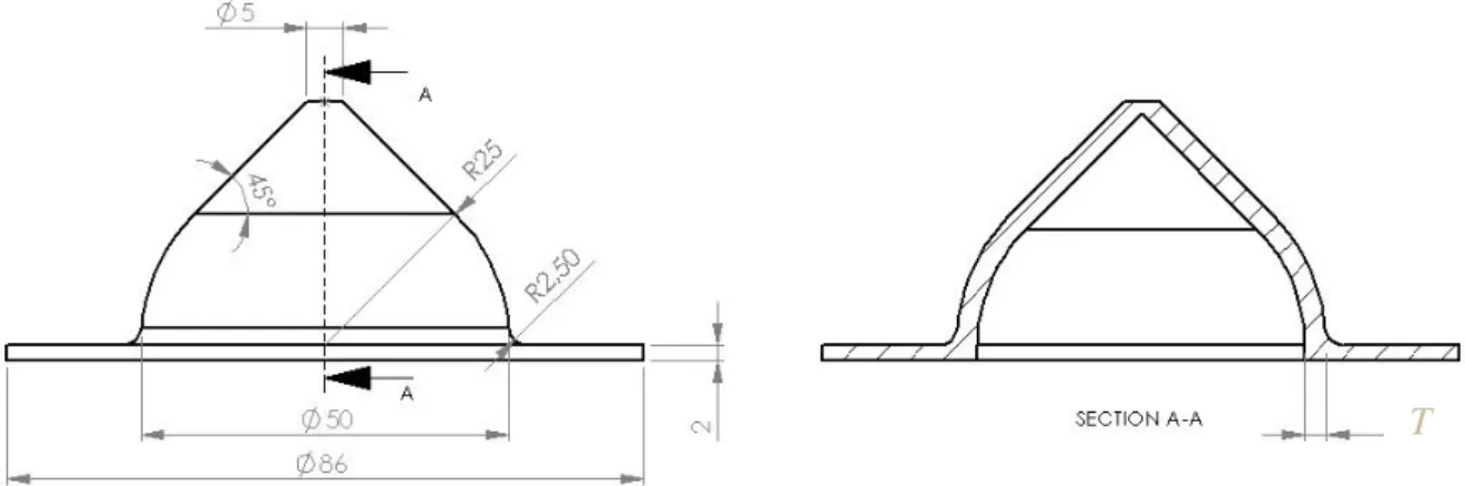
5.1.2 Performance of Sealant Under Pressure Test Specimens
Specimen 1
A full description of the design of this initial specimen can be found in chapter 6.1.4: Design Development.
Figure 17: Initial sealant under pressure test specimen dimensions
Specimen 2
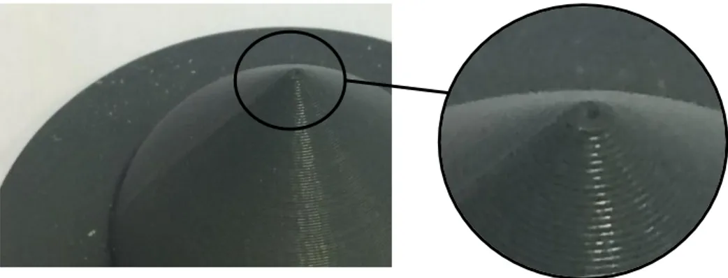
An explanation of the change in design can be found in chapter 5.5.2: Performance of Sealants Under Pressure.
Figure 18: Second specimen design with altered tip
5.1.3 Flexural Test Specimens
The flexural test specimens for ABSplus-P430 and Ultem 1010 have been designed in accordance with ISO178:2019 standards. The dimensions are as follows:
Figure 19: Flexural test specimen dimensions
5.2.
Manufacturing of Test Pieces
5.2.1 ABSplus-P430
The ABS porosity, sealant under pressure and flexural test specimens were manufactured in the Stratasys uPrint SE Plus FDM printer. The printing parameters were set using CatalystEX and can be seen below. Porosity specimens were printed in the X direction and the sealant under pressure specimens were printed flat with the conical shape point upwards and no support material. Flexural specimens were all printed in the same direction to ensure sameness. Half of the flexural specimens were printed in the Y direction while the other half were printed in the Z direction. Figure 20 below displays a pre-picture of how the Y direction specimens will be printed, and as seen, they are all printed in the same direction.
The porosity specimens and sealant under pressure specimens were then subjected to various forms of sealants, including acetone vaporization, two spray sealants, and a combination of acetone vaporization and sealant.
The acetone vaporization procedure followed those of a similar test (Neff et. al, 2016). A napkin was soaked with 10 ml of acetone and was placed around the perimeter of a glass vessel. Specimens were placed so that they did not touch each other and that the maximum amount of surface area would be affected. The glass vessel was sealed and the specimens were left for 1 hour. After, the specimens were taken out and were left to dry for 3 whole days to ensure any remaining acetone had evaporated before testing or applying the next post-process.
The two sealants used were a URC200D (Electrolube), a high perfomance urethane coating and HPA 200 H (Electrolube), a high performance acrylic coating. Both sealants are commonly used as electronic protective sprays against abrasion, corrosion and humidity. The sealants were used as instructed by the supplier. Two spray treatments were applied to the test specimens, on the entire porosity specimen while only on the top side of the sealant under pressure specimen. The sealant under pressure specimen’s flat edge was sprayed a third time to ensure that it was not the weak point. The treatment which proved to be most effective was then applied in the same manner to flexural test specimens.
All specimens were then dried for the alloted 88h at 23°C at 50% humidity in accordance with ISO 291:2008 before testing.
5.2.2 Ultem 1010
Ultem 1010 test specimens, including ‘sealing under pressure’ and flexural, were manufactured in the Stratasys Fortus 450 FDM printer at 0,25 build height. Certain specimens were then sent to Polymertal to be plated. Plating was carried out based on Polymertal’s expertise on the subject. All specimens were plated with copper at 60 µm thick.
All specimens were then dried for the alloted 88h at 23°C at 50% humidity in accordance with ISO 291:2008 before testing.
5.3.
Material Tests
5.3.1 Porosity Test
Porosity test procedures of the vaporized and sprayed specimens followed the ISO 62 standard for water absorption. The specimens were weighed and then immersed in distilled water at room temperature for 1 hour. Afterwards, the specimens were dried off using a dry cloth and immediately weighed again. The percentage change in mass is then calculated c by using the following formula, where 𝑚1 is mass before immersion and 𝑚2 is mass after immersion:
𝑐 = 𝑚2− 𝑚1 𝑚1
× 100%
5.3.2 Performance of Sealants and Plating Under Pressure Test
The sealant under pressure test followed procedures of a similar test (Mireles et. Al, 2011). A test pressure vessel was manufactured from a polyurethane block, BM 5173, with a flexural strength of 80 MPa using a Brother TC-S2A CNC milling machine. Once the test specimen was fitted in the vessel, they were both submerged in water. The vessel was connected to a compressed air source. The vessel was then filled at a rate of approximately 1 bar/min up to the max pressure of 8 bar (0,8 Mpa) and was then held constant for 5 minutes if the specimen passed initial pressures. The pressure at which air bubbles formed on the visible side of the test specimen was noted. 1 specimen was tested per sealant. Figure 21 displays the test vessel and setup.
5.3.3 Flexural Test
The flexural test followed the ISO 178:2019 standard for such tests. ABS-P430 (Y) and (Z) specimens as well as ABS-P430 (Y) and (Z) post-processed specimens were tested. 5 specimens were tested for each, resulting in 20 tests. Ultem 1010 (Y) and (Z) specimens as well as Ultem 1010 (Y) and (Z) specimens with additional copper plating were not tested due to delays in post-processing. O-rings Pressure inlet Test specimen Bolts
Figure 21 (a) Cross section of sealant specimen inside pressure vessel (b) Top view of pressure vessel with o-rings
(c) Angles view of pressure vessel with test specimen inserted (a)
(b)
5.4.
Results of Material Tests
5.4.1 Porosity Test
The table below displays the results of the porosity test. See chapter 4.6.1: Vaporization and Spray Sealants for further description of exposure environment and/or sealants used on test specimens. See chapter 5.3.1: Porosity Test for test method and result calculation.
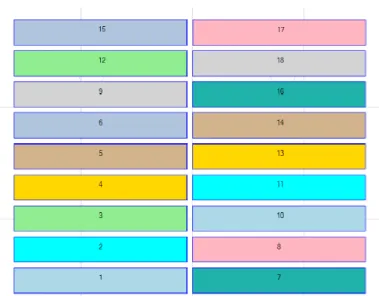
Table 4: Results of ABS-450 Porosity test
Exposed to Test Results
Sp. None Acetone Vapor Urethane Spray Acrylic Spray Polishing Initial Weight Final Weight c (%) 01 ✓ 3,93 3,93 0 02 ✓ 3,91 3,92 +0,3 03 ✓ 3,94 3,94 0 1 ✓ 3,89 3,90 +0,3 2 ✓ 3,9 3,91 +0,3 3 ✓ 3,9 3,91 +0,3 4 ✓ ✓ 3,95 3,95 0 5 ✓ ✓ 3,91 3,92 +0,3 6 ✓ ✓ 3,94 3,95 +0,3 7 ✓ ✓ 3,94 3,94 0 8 ✓ ✓ 3,93 3,93 0 9 ✓ ✓ 3,93 3,93 0 10 ✓ 3,93 3,94 +0,3 11 ✓ 3,93 3,94 +0,3 12 ✓ 3,94 3,95 +0,3 13 ✓ 3,92 3,92 0 14 ✓ 3,92 3,92 0 15 ✓ 3,93 3,93 0 16 ✓ 2,05 2,05 0 17 ✓ 2,07 2,08 +0,5 18 ✓ 2,05 2,05 0