Postal Address: Visiting Address: Telephone:
Box 1026 Gjuterigatan 5 036-10 10 00
551 11 Jönköping
The reuse of design rules by product and process
documentation - A descriptive case study
Emma Andersson
Bachelor’s Thesis 2010
Mechanical Engineering
Postal Address: Visiting Address: Telephone:
Box 1026 Gjuterigatan 5 036-10 10 00
551 11 Jönköping
The reuse of design rules by product and process
documentation - A descriptive case study
Emma Andersson
This thesis work is performed at Jönköping Institute of Technology within the subject area product development. The work is part of the university’s three-year engineering degree. The author is responsible for the given opinions, conclusions and results.
Supervisor: Fredrik Elgh Credit points: 15 hp (C-level) Date: 2010-12-20
ABSTRACT
The problem of automating design processes is often related to the difficulties with updating, maintaining and sharing the information. This thesis provides a descriptive case study of a large company’s design automation process and the difficulties of reusing already existing solutions.
The main purpose of the thesis has been to trace a product family from its specification of demands to a complete design program. An account is given of the documentation written during the product development process, of the different data storages and also how the company has implemented design automation in their process.
The results have been reached through a series of interviews as well as previous studies and material from the company. From an analysis of the results proposed solutions are given and focus on the low quality the documentation has and how it is a result of a rapid growth within the company.
KEY WORDS
SAMMANFATTNING
Problem vid automatiserandet av designprocesser är ofta relaterade till svårigheterna med att uppdatera, underhålla och dela informationen. Detta examensarbete tillhandahåller en beskrivande fallstudie av ett stort företags regelbaserade konstruktionsprocess och svårigheterna med att återanvända redan existerande lösningar.
Huvudsyftet med examensarbetet har varit att spåra en produktfamilj från dess kravspecifikation till ett färdigt konstruktionsprogram. En redogörelse ges för dokumentationen som skrivits under produktutvecklingsprocessen, för de olika datalagringarna och även för hur företaget har implementerat regelbaserad konstruktion i sin process.
Resultaten har nåtts med hjälp av en serie intervjuer så väl som tidigare studier och material från företaget. Från en analys av resultaten ges förbättringsförslag med fokus på den låga kvalitén dokumentationen har och hur det är ett resultat av en snabb tillväxt i företaget.
ACKNOWLEDGEMENTS
This bachelor thesis has for the majority of the time been carried out at the company Sandvik Coromant, Sandviken, Sweden, and I am grateful for all help the department of design programming has given me. A special thank you goes to my supervisor Lena Persson who, during my weeks in Sandviken, daily guided and encouraged me.
Finally, I would like to thank my supervisor Fredrik Elgh at the School of Engineering, Jönköping University, for his guidance and patience.
Table of contents
TABLE OF CONTENTS
1
INTRODUCTION ... 1
1.1 THESIS BACKGROUND ... 1 1.2 COMPANY PRESENTATION ... 2 1.3 PRODUCT DESCRIPTION ... 31.4 PURPOSE AND AIMS ... 4
1.5 DELIMITS ... 4
1.6 PREVIOUS RESEARCH ... 4
1.7 OUTLINE OF THE THESIS ... 5
2
THEORETICAL BACKGROUND ... 6
2.1 DESIGN AUTOMATION ... 6
2.2 KNOWLEDGE BASED ENGINEERING... 7
2.3 MOKA ... 8
2.4 PLM ... 8
2.5 PDM ... 9
2.6 DOCUMENTATION ... 10
3
APPROACH ... 11
3.1 METHODS AND TOOLS... 11
4
RESULTS ... 12
4.1 DESIGN AUTOMATION AT SANDVIK COROMANT AB ... 12
4.1.1 Current difficulties ... 12
4.1.2 Tailor made ... 13
4.2 INVESTIGATING COROMILL 490 ... 13
4.2.1 Information storages ... 14
4.2.2 Departments ... 15
4.2.3 Updating a product family ... 16
4.2.4 Document handling... 16
5
ANALYSIS ... 18
6
PROPOSED SOLUTIONS ... 20
7
CONCLUSIONS AND DISCUSSIONS ... 21
8
REFERENCES ... 22
Introduction
1
1 INTRODUCTION
The introduction contains the thesis background, followed by a short company presentation and the investigated product’s background. It also describes the thesis’s purpose and aims, the previous research background and the outline detailing the structure of the thesis.
1.1 THESIS BACKGROUND
In the research and development department of Sandvik Coromant AB there has during the last few years been a change of the operation method to become more efficient in the product development process. This has resulted in an automated business process from customer order to the delivery of the complete product in a very short period of time. The necessary changes the company had to make for this automation include implementing advanced systems based on design rules which generate the relevant product information. This includes preparation; cost-estimation, 3D-models, NC-code, measurement instructions, etc.
In the product development process each product family gets their own defined separate instances like any other product on the market but here the process also includes the establishment of design rules for a so called “product space”. The product space makes it possible for a tailor made product to be generated in a few minutes with all the necessary information included.
The change has meant a shift in the organization with new working details and methods. There is a constant need for new methods and tools to support and streamline the work to become even faster in the development of new products. Reusing is an important strategy at Sandvik Coromant and is partly done today but there is a need to further improve the use of old knowledge.
Introduction
2
1.2 COMPANY PRESENTATION
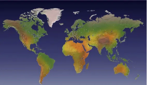
Figure 1. Sandvik is represented all over the world, www.sandvik.com (Acc. 2010-04-21)
Sandvik AB was founded in 1862 in Sandviken, Sweden, under the name Högbo Stål & Jernwerks AB, as a steel-producing industry and invested early in high quality, research
and development. Today the Sandvik Group is represented in 130 countries (figure 1) and has 44.000 employees all over the world with expertise knowledge in many areas of material technology. The business philosophy has been largely the same through the years [1]: “Sandvik shall be the leader in selected areas. Products are based on high value content and are developed in close cooperation with customers. Quality is the guiding principle in the global operations.” The company’s goal is to contribute to costumers’ productivity and profitability by providing products and services of maximum value. The Sandvik Group has concentrated their operations to three core business areas to ensure a continued strong expansion; Tooling, Mining and Construction, and Materials Technology (figure 2).
The Tooling business area focuses mainly on tools and tooling systems for metalworking applications. Major customers include companies in the automotive and aerospace industry.
Mining and Construction specializes in rock-working equipment and tools used in mining and civil engineering worldwide.
Materials Technology mainly develops products in stainless steel, special alloys and resistance heating materials as well as process systems. Customers can be found in most industrial segments.
Introduction
3
Figure 2. The organization of Sandvik Group,
www.sandvik.com (Acc. 2010-03-29)
Sandvik Coromant AB, where the case study was conducted, was started in 1942 as a small cemented carbide tools department and is today a part of Sandvik Tooling and is the world’s leading producer of tools for turning, milling and drilling.
1.3 PRODUCT DESCRIPTION
Coromill 490 has been the chosen product family to investigate in the case study and the steps from the specification of demands to a complete design program has been traced and documented.
Figure 3. Arbor, Coromant Capto and Cylindrical tool holders, http://www.sandvik.coromant.com/se
(Acc. 2010-04-07)
Currently there are thirty-two active product families in the milling branch of Sandvik Coromant AB and Coromill 490 (figure 3) is a new generation face and shoulder mill [1]. According to Sandvik Cormorant’s product description [2] it can reduce the machining costs up to 25% where less but more precise work is needed, is ideal for small depth of cut and offers three different pitch choices; course, close and extra close. It can produce a finished product in one pass and has low cutting forces on the four-edge inserts do to innovative insert geometry. The different types of milling where the Coromill 490 can be applied are many and with one tool it can replace several others.
Introduction
4
1.4 PURPOSE AND AIMS
The main purpose of the thesis has been to develop a solution for the reuse of the digital descriptions of already existing products. These descriptions consist of both CAD-models and design rules for the generation of product variants.
In order to reuse existing solutions, access to old knowledge is required to further develop solid solutions and implement them in new families which will prevent unnecessary and repetitive work. The purpose of this thesis has been to track the existing knowledge in a product family, Coromill 490, and maintain an account of the different descriptions established during a development project. The product has been traced from its specification of demands to its complete design program, with an analysis of how the descriptions are handled. The descriptions content concerning extent, completeness, quality, purpose, target group has resulted in suggestions for improvement with the goal of an increase in the reuse of CAD-models and design rules.
1.5 DELIMITS
The main task has been to map the process from specification of demands to a complete design program for the product family Coromill 490. The focus has been aimed at the CAD-models and the design rules since they were the documents for which future reuse would depend upon. Suggestions for improvement were to be given depending on the time schedule alternatively suggestions for how future researchers should handle the results of the thesis.
The thesis has not taken other product families’ methods and how their data is stored and handled into consideration but occasionally speaks in more general terms of the development process.
1.6 PREVIOUS RESEARCH
It was through a research project this thesis was outlined and is a part of a collaboration between Sandvik Coromant AB and the School of Engineering at Jönköping University.
In product development and engineering design the need for decreasing tedious routine tasks is great and the lack of supporting methods to reduce the redesigning of existing solutions could be solved using computer automation. Companies who base their business strategy on customized products usually have design automation systems integrated in their manufacturing process, a method to reduce lead times and increasing efficiency etc. A problem for companies who have successfully implemented these systems has been to keep them updated, accurate and useful. The School of Engineering, at Jönköping University, has during the past two years (2008-2010) conducted a research project on design automation strategies to improve today’s practice for the manufacturing industry. The project was funded by The Knowledge Foundation, a Swedish research financier for universities, and the
Introduction
5
participants were four Swedish manufacturing companies, two international big business companies and two medium-sized companies. The School of Engineering motivated [3] the value of the project with the lack of international, scientific work in the area of updating, adapting and maintaining design automation systems. The project planned to focus mainly on two aspects; management of design knowledge and multiple knowledge sources and flexible solution search.
1.7 OUTLINE OF THE THESIS
Chapter 1 is the introduction and provides with the general background for the thesis, the company and the studied product.
Chapter 2 presents the necessary information about the thesis subject in theory and is not a description of how the company itself is structured.
Chapter 3 describes the methods, tools and what approach was used to investigate the thesis problem.
Chapter 4 lists the results and findings from the interviews and read material from within the company. It also presents the concerned departments and the work they do.
Chapter 5 analyses the results from the previous chapter.
Chapter 6 offers solutions to the current situation based on the analysis.
Chapter 7 summarises and concludes the thesis. Finally, suggestions for future research are discussed.
Theoretical background
6
2 THEORETICAL BACKGROUND
To understand the problem presented in this thesis a theoretical background on the subject area is necessary. Automating processes in companies today is common and there have been many books and research papers written on how to introduce the methods. The following chapter will describe what it means to automate tasks and what the effects can be. It will also briefly mention PLM and PDM, which is a way to handle and manage information around a specific product. Lastly this chapter ends with a mentioning of general documentation; how it is viewed upon and handled in the manufacturing industry, something which is highly relevant to this thesis.
2.1 DESIGN AUTOMATION
For industrial companies the demand for customized products to be delivered on the same terms as mass-produced products has become an important competitive factor which involves price, quality and delivery time. There is therefore an increased interest among many companies to automate their product processes with the purpose of reducing lead time and human involvement to produce products faster and at lower costs. For a company to implement design automation in its organization the requirements are varying depending on the extent and what parts of the process are intended to be automated, but the benefits of using this method are many. Some of the typical effects in a successful implementation are [4]:
A time reduction from weeks to minutes when working out specifications. Faster and more qualified responses to customer needs. An offer can with
this method be given much faster and require less resources for the company.
Fewer transfers of responsibility and fewer errors in the specifications.
A time reduction in specifying customized products’ offers and more time for product development and other creative work task. Both of these reduce time and makes better use of the employees.
The possibility of optimizing products to the costumers’ needs with reduced costs, for example in materials and production.
Implementing design automation in a company often means a formalization of product, production and assembly information. In some cases these can be described as configuration systems which generate the desired customized product. Depending on the number of parameters for the different parts of the product the combinations can be infinite, making each generated product unique.
There are companies that have attempted to implement configuration systems but met with difficulties or stopped using successful systems because they have not been continually updated. Some of the problems a company can experience when developing and implementing a configuration system are [4]:
Theoretical background
7
Insufficient clarification of why the configuration system was developed and implemented to the people currently running the project, who are possibly only technically-oriented. The project therefore has a need for more customer-oriented people.
The necessary support from the management has been insufficient and the configuration system is not rooted enough in the organization. If the system is not updated continually with the latest knowledge it will become out of date and less useful.
The products are not configurable, meaning the product families and their variations have not been clearly defined. Possibly due to a lack of agreement about which variants should be offered and to what market segments.
The developed configuration system has not been structured or documented, making it near impossible to maintain and develop further. A problem which often arises when the system is being programmed without an overall developed and documented description of the system.
2.2
KNOWLEDGE BASED ENGINEERING
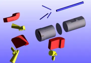
A similar topic to design automation is knowledge based engineering (KBE) which is far more advanced with higher introduction risks than a configuration system. KBE is defined as ”The use of advanced software techniques to capture and re-use product and process knowledge in an integrated way” [5] . It is however suggested that the subject lacks a description since its limitations has not yet been defined and its’ potential only limited by our own imagination. For a better explanation of what KBE is a comparison to CAD (Computer Aided Design) packages, which is more commonly known, can be made. With CAD objects can be designed in both two and three dimensions from which drawings can be generated automatically and is widely used by designers, architects, and developers (Figure 4). While CAD only handles a single product design and only generates geometry, KBE has generic knowledge of a product family thus making it possible to generate similar products within the family based on that knowledge.
Figure 4. “Parts of a milling product created in a CAD-program; put together they are called an
Theoretical background
8
KBE-applications have been most successful when routine design tasks are time consuming, normally in a project involving people from different expert areas. In large companies design processes can be based on years of experience within a specific area but the knowledge of how and why they are designed in their particular fashion can be difficult, if not impossible, to trace. KBE can in situations like these be used to hold the knowledge of the product and the process. The knowledge should be stored in an accessible way to support modifications and updates since it’s used in a presumably rapidly developing industry. The re-use of old knowledge can be the most beneficial time and cost reduction a company can make but requires the stored knowledge to be of high quality. This is something that can require specialists who hold the knowledge about the knowledge and is therefore highly undesirable. To avoid that problem and to make the recorded knowledge understood by everyone a system called MOKA was created, a specific tool for handling KBE applications.
2.3 MOKA
Methodology and software tools Oriented to Knowledge based engineering Applications (MOKA) originated as a project spanning over 30 months partly funded by the European Commission with the purpose of addressing a few basic needs such as those above.
MOKA’s purpose, as previously stated, was to reduce the cost, risk and time when creating a KBE application and automates repetitive, routine design tasks. In order to make this possible three needed key elements were formulated [5]:
A described lifecycle.
A representation of both the product and the process knowledge. Creating a software tool to implement the methodology.
MOKA is designed as a neutral format to enable its use in any kind of KBE-package and is structured to be used on two levels, one more user-friendly understood by most and another more formal second level with higher demands on the stored knowledge.
If the product and design process knowledge is effectively managed it will reduce the effort to re-capture, re-structure and re-code knowledge for a new application.
2.4 PLM
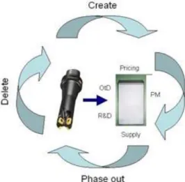
Product Lifecycle Management (PLM) is an activity which focuses on the company’s products instead of e.g. Supply Chain Management or Enterprise Resource Planning. PLM manages the product from its creation to its deletion in an effective way and helps keep control over the product. Figure 5 demonstrates a simple visual drawing of PLM at Sandvik Coromant. [6] It can help a company reduce costs and time for product development and engineering changes, improving the product’s competitiveness. Managing all the information created during a product’s lifecycle can be difficult to handle without a proper overview, something PLM can provide.
Theoretical background
9
Figure 5. Product Lifecycle Management, internal PLM description at Sandvik Coromant
(Acc. 2010-04-07)
Handling a complete solution with support, compared to single product, will increase the complexity even further and increase the need for better management. Other examples of increased complexity in creating a product can be new demands and regulations, e.g. for decreasing the environmental influence, which can constantly affect the manufacturing and distribution.
PLM cannot be handled by a single department, such as finance or engineering, because it is involved in all departments and is a management issue. Therefore the company that doesn’t already use PLM will have to restructure its organization and work around the product instead of in the traditional departments.
The data which is generated in a product’s lifecycle can be very difficult to manage with many unknown relationships and sometimes with no real purpose. PLM allows the company to handle this complex environment in a more structured and logical way.
2.5 PDM
Product Data Management (PDM) is a component within the PLM which manages the product data and the product workflow [6]. It can be seen as an earlier version of PLM as well when it was created in the late 1980s to help keep track of design files generated by CAD-systems. With PDM it was now possible to store and control document files and see relationships between parts and assemblies. This system also allows more files and product data to be reused and the risk of using incorrect design data is reduced.
Using PDM-systems within PLM is a way to manage activities in the product lifecycle such as the specification and the product’s definition [7]. The improved control over the lifecycle will enable reuse of design information. The driving force in companies to use PDM however is mainly the business’ need to increase productivity and to respond more flexibly to customers.
Theoretical background
10
2.6 DOCUMENTATION
In most engineering areas documentation is seen as a tedious and often time consuming task no one will read but is required in a project or task. When documenting design rules for a configuration system or just general engineering information there seldom is a suitable computer program to handle that kind of information in a structured and presentable way [8]. Documentation is often done after a completed project, which can span over several years, instead of continually updating it throughout the development phase. At that point important things might have been forgotten and changes that have been made have not been properly documented and the project’s time and money may very well be spent.
To be successful with documentation in mechanical construction the what and why needs to be properly defined before initializing the actual documentation. The product’s geometry is often documented in the form of a solid CAD-model but non-geometric information is more difficult to handle and each CAD-system all vary in that aspect. When design rules are to be documented, whether they are trivial or complicated, there is little room to present them in.
Documentation for the clients, such as manuals, drawings etc. makes the need for high quality much easier to understand since it’s a prerequisite to get a product sold. Documenting for oneself or coworkers however is more difficult to see the importance of, even though it is probably the company’s most protected secret that needs to be detailed. Detailing why the product is designed as it is will not only support reuse but also prevent changes to it that could have serious consequences to its function. If it costs more to document known methods and product details than to re-do and reach the same conclusions a second time, the quality and credibility to the documentation is probably too low or too difficult to comprehend.
Approach
11
3 APPROACH
The approach describes how interviews have been the main tool for collecting information and also the mapping of the creation process of Coromill 490.
3.1 METHODS AND TOOLS
The work has been conducted through a series of interviews with a few representatives from each activity in the process chain; product management, product development and design programming. They provided with the knowledge of where the relevant information is stored for each activity and how it is used to set the current boundaries in a project. By working backwards through the process chain, starting with design programming, the necessary insight to the main problem was given.
In a large company such as Sandvik Coromant there are many different experts involved in creating a product and to find computer systems that suit everything and everyone is often difficult. There are few people who can say where necessary information is kept that don’t directly concern their specific work but the information still has a vital role in the completion of a product or project. Understanding why work tasks are executed as they are, and what they are, is a step closer to improving the process.
To better understand and map the information flows, where it is stored and who uses it, a process map of the product family Coromill 490 was drawn up. After thirteen versions a better view of the different activities involved could be seen and made it easier to trace the necessary information for the thesis. The organization, with its many departments and several different information storages, had made the connections difficult to grasp. With the aid of the conducted interviews the process map grew and changed with each involved person until it was as accurate as possible. [Attachment 1]
The first set of interviews was done during the first and second week with the purpose of giving an insight and understanding to how the organization functioned and operated. A follow-up set was made a few weeks’ later when sufficient material and knowledge had been gathered to enable a deeper apprehension of the different departments’ job descriptions. The interviews were conducted with a pre-written form drawn up to find the necessary answers in a uniform way. Though not all questions were relevant to that specific department, the majority suited the recipients. The form [Attachment 5] was divided into five categories and was methodically worked through at each meeting.
Results
12
4 RESULTS
Through interviews and text material given by the company, the results describe design automation and how it is practiced at Sandvik Coromant and the different information storages and their function are mentioned. Finally, the three concerned departments and the guidelines for documentation handling are given a short presentation.
4.1 DESIGN AUTOMATION AT SANDVIK COROMANT AB
Sandvik Coromant has been very successful in using KBE and began in the mid-seventies to automate offers and orders in computer systems. The majority of the tools produced today are created by the KBE-system with the exception of special tools.
4.1.1 Current difficulties
One of the problems the company is presently facing is that the computer systems developed for CAD/CAM/CMM will in the near future no longer be supported or further developed [9]. The KBE-systems at Sandvik Coromant have been evolving during a long period of time on different technology levels making the integration between the disciplines difficult. There are currently four parametric design programming systems in active use: GRIP, Smart Elements, DSHELL and C. These systems are all written in different languages and cannot communicate with each other and a new programming platform is currently being developed by the company, YAPP. The new platform will replace Smart Elements and is expected to require less programming skills by the engineers and to be more efficient in geometric analysis, NC preparation and marketing.
Another problem the company during the last few years has faced is a fast growth and a need for reorganization. The expansion has meant an increase in personal with more specific work details which has separated the developers, constructors and programmers more from each other. The understanding for what each expert works with and requires has diminished. In order to reuse information at the company today it has to fulfill some requirements or it won’t be sufficiently trustworthy to use [9]:
The information has to be stored in a structured way on a system-independent model.
It has to be possible to view where the information currently is used and has been used.
The information has to be quality assured. The information has to have an owner.
The use of the information must be easily understood. The information must be accessed fast and easy. It must be easy to update and in a controlled fashion.
Results
13
The information must be possible to versioning.
4.1.2 Tailor made
Tailor made is a term the company uses to promote the parametric product program which makes it possible to order products beyond the standard assortment. The potential products generated within the product space can be infinite depending on the desired parameters. Alternatives available for Coromill 490 for example are the insert’s size, the division of the inserts and what type of tool holder system could be used. Orders are made with the aid of W-routine, an input data routine for the parametric program. The parameters are given their values by the routine.
Figure 6. Product space (CTPP) 2010-04-09
Instances are the standard products (the red dots in figure. 6) in a family and for the majority of the families there are design rules that acts as a frame in which tailor made products are generated. In the automated tailor made process the unique product is created from the desired parameters of the customer.
4.2 INVESTIGATING COROMILL 490
The product family Coromill 490 is relatively new and is mostly based on newer working methods. The following presentation will describe the organization and information exchange between the different experts who are involved with creating the product family. The three main involved types of experts were representatives from Project Management, Product Development and Design Programming.
The process [Attachment 1] can be traced from the specification of demands to the complete design program, ready for production. The product family had not yet been closed during the thesis but has been partly released two years previous. The information sources of the family was therefore not completely updated and held none or little information.
Results
14
4.2.1 Information storages
The different places the information is kept make it difficult to handle and update and the large company has several information storages:
Topas
Topas is a project database in which all experts involved are given access. The database contains project-status reports, protocols, traveling reports, technical memos, lab reports and project plans.
UGC-fileserver
The fileserver is a computer catalog with the purpose of storing all the CAD-parts for the product and can be accessed by project members. There are no directives of where design rules should be kept during the development process and for the simplicity of working with these copies can be found in the catalogues.
Design Rules
In the company’s Intranet the product family is on completion uploaded to the page Design Rules [Attachment 4] where a description of the product and the design rules are kept. The uploading process is done by copying and pasting design rules from drawings and files. Pictures of the product are manually moved from the correct angle in the CAD-program and the print-screen function is used to lift the picture to the Intranet.
PC Toolfile
The IT-system contains the company’s product data such as classifications, geometry, recommendations etc. The information is used to Sandvik Coromant electronic product catalog, TINA (Tool Investment Analyzer), other software systems and also provides data for the paper catalogues.
RI – The drawing record
The drawing record at Sandvik Coromant was develop in 1976 and made it possible to store drawings in a computer system rather than binders. Information that is included in these is creation date, product code, category, brand, revision, distribution plans etc. Today the company doesn’t store drawings of a complete tool, for example the production drawings, since W-routine and design programs are used to generate them whenever they are needed. All drawings that are registered in RI must be of the latest version. The system is still in effect because it is connected to several other systems and also because of the format in which the drawings are stored. The drawings do not demand any particularly CAD-program like UG (Unigraphic) and can therefore be viewed by others who don’t necessarily work with 3D-modeling. The drawing record will in time be replaced when a PLM-system has been successfully implemented.
Results
15
Computer catalogs and personal binders
There is also information stored on an individual level in binders and catalogues which can hold valuable data of a project but is difficult to evaluate.
4.2.2 Departments
The product development at Sandvik Coromant AB is conducted in the research and development department CTP, an abbreviation of Coromant, Tooling and Product development. The involved experts in the product family Coromill 490 are the product development for milling tools, design programming and product management.
The thesis was mainly conducted in the design programming department where the design rules are put in a program which can then generate unique products from the parameters of the customer’s choice. The limitations of these parameters are made by the Product Management and are included in the product specification they create based on the markets need.
Product Management
Product management is the company’s contact with the clients and the market. They plan and forecast new products but are not structured hierarchically with the product development or design programming. Product management set the requirements the new product must obtain and how large the product space should be, i.e. how many variances it should offer the customers.
Product Development
The Product Development handles the design and the construction of the product family. From the specification of demands a knowledge project is, if necessary, put together to determine what resources and qualifications the project members will need to obtain. Through communication with Product Management the specification of demands is adjusted depending on what is possible and what is not with the given resources and time frame.
The project database Topas contains all reports, tests, results and meeting protocols. It is mainly used by the product developers during the development phase to handle all documentation around the process. The product work files, such as CAD-models and Excel-documents of product details, are kept in the UGC-fileserver. They work after a Product Project model [Attachment 3] with five stages, each requiring an evaluation report, with objective checks from other departments, before continuing. In attachment 2 there is a drawing from the Coromill 490 family together with its design rules. These rules are difficult to understand for those less experienced with this type of working method. The rules can sometimes simply be a safety factor based on empirical studies with no theoretical support or it can be a physical property only the constructor understands. The circled area in the drawing displays
Results
16
what the programmers’ base their coding on when writing the parameter files. The format, and lack of explanation, prevents the program to be used to its fullest potential and makes it more difficult to determine if it can be used in another project.
Design Programming
The design programmers receive design rules and CAD-models from product development for which the latter is prepared with geometries, datum features and name surfaces for CAM (Computer Aided Manufacturing) and CMM (Capability Mauturity Model) in the design program. The design rules are translated to code in the design program and in the case of Coromill 490, the design program DShell was used. The design program puts the 3D-parts together and creates the necessary drawings for offers, compilation and production. It also prepares the model for processing and CMM.
The quality of the input the design programmers receive is an important factor for a successful program [10]. It makes it easier to delegate to others and see what has been written, but also makes it possible for the program to be reused or partly reused. The format in which the design rules are presented is varying depending on who has written them. Examples of how they can be presented are drawings, Excel-, Word documents and occasionally on post-its which are then interpreted by the programmer.
4.2.3 Updating a product family
When a change in a product is made there is an application called DMT which must be used to notify those who are affected by the change. The change has to be approved and sometimes go through several experts before being used. Product changes have occasionally been made through calls or hand-written notes resulting in an instantly made change. This quick solution can sometimes be seen as more effective but creates new problems instead which are not registered anywhere and the initial problem is not documented and cannot be taken into account in any future projects. If an adjustment is made to a 3D-part and has not been sent through proper channels it can change other products as well as the intended depending on how many products use that specific part. Knowing these types of problems exist decreases the reliability and creates confusion of what the most recent version of information, with the potential of being reused, is.
4.2.4 Document handling
In the manual of operation there are guidelines for how new knowledge should be shared, valuated and distributed quickly for others to use. The knowledge should also be stored in a way to suit future reuse. All written information should be documented simultaneously with all activities and presented so that the content could easily be apprehended, valuated and used.
Results
17
Certain documents are indexed and kept in archives [11], the CT-archive and the electronic database Tooling Reports Library, with a unique document number and secrecy code. These include: project status reports, protocols, traveling reports, technical memos, lab reports and administrative content. All other documents should be stored with each department. In all pre-studies or similar work tasks an investigator should use the archives subject-oriented searches to use available knowledge and reduce double work.
Analysis
18
5 ANALYSIS
The strongest impression Sandvik Coromant made was the amount of information held in many different places, seemingly without any greater structure and with difficulties to access quickly. There are many steps of access approval once you know where to acquire certain data but it is not necessarily kept in the best place or places. There is no guide or collection of useful links to offer an overview of the information storage or flow but relies on individuals’ capacity to orient themselves, a weakness which could reduce efficiency. The reliability of the information is also questionable when there is little way of telling if it’s the latest version or not. To reuse data from other projects is not common in the current state because of the lack of documentation done during the product’s development phase. Another way of looking at it would be that there is too much information in one place drenching the important and valuable data which could enable future reuse.
There is not enough evaluation of what data could or could not be reused for the future. The manual of operation suggests, see part 4.2.6, that all pre-studies should include an information search in the archives from older projects. This is however not practiced, probably because of the amount of all kinds of information stored in the same place. The manual of operation mentions that department-specific information should be stored with the department but there is no collection of that type of information in one place. Much relies on people with years of experience to find the right place to look in, if they know what they are looking for.
New demands have been made during the past few years to deliver new products within 18 months though nothing has changed in the design programming process to make it more efficient. Most of the ruled-based engineering at Sandvik Coromant is made sequentially but it is perceived that if the process were to be made clearer the work could be conducted more parallel between the departments it could offer faster and more efficient results. The design programming is seen as a bottleneck in a project because the experts from that department join relatively late which is a result of the lack of data they receive in the earlier stages of the development process. The design rules and design programs could be of higher quality if it would be possible for them to start the programming earlier in a project.
The lack of tools to facilitate documentation of high quality, to store it in a more accessible way and to make it more comprehensively, is also an issue. Using Microsoft Word and Excel for the majority of the documents the company uses is not ideal for the engineering profession. The documentation, e.g. evaluations, field tests, progress reports and lab reports, is created in these computer programs and the content, quality, extent and purpose of the documentation is left to the individual writer.
When a project is finished, like Coromill 490, the design rules, together with other product data, are put on the company’s intranet, in Design Rules. The changes that have been made in the design rules during the project are not always updated to the
Analysis
19
ones that have been sent to Design Rules and the credibility is therefore low. The most reliable source of a product family’s accurate data is the running design program for a product where the information has been translated to code.
It is not uncommon for the documentation to suffer in a tight time-scheduled project since it is not considered a prioritized activity in the process which becomes a disadvantage for future projects.
There is a guide on how to create Design Rules in Correct Ways but only gives a general description of what it should contain [Attachment 4]: “The aim of it is to achieve understanding of what information that is important and in that way create good documentation of design rules and make the writing of W-routine and design program as efficient as possible.” There is no template of how it should be designed though most product families look the same. This is another time-consuming process that is sometimes over-looked and has no set deadline or check-up when the information needs to be made accessible.
The company, so far advanced in its business field, has surprisingly old and out-dated methods to handle the data they generate. Using copy and paste from one document to another for publishing on a page for official use with little assessment and continual update is not a modern procedure.
On the initiative of an individual programmer a list was kept and updated in the project database each time a change was made in the design program, changes which there are no records of anywhere else but the changes made during the product’s lifetime cannot be stored there since the project database is archived once it is released. This is another example of the lack of tools the company possesses to control the information flow and individuals find their own solutions outside the process.
Proposed solutions
20
6 PROPOSED SOLUTIONS
Separating, emphasizing and possibly storing the relevant knowledge for future reuse in a better and more accessible place could be a more beneficial method than the current. Similar storage archives, such as those mentioned in part 4.2.6, should be in place but with improvements to avoid the present situation where the information is not put to use. There is a strong will to be able to work more efficiently and if the quality of the information between the activities improved more tasks could be performed more simultaneous than today’s current sequential methods.
Reuse is a time saving method and should be encouraged and emphasized in all projects. If it is more cost-effective to re-do already existing work it is probably either because of the low quality of the documentation or the difficulty apprehending it. When a member is replaced in the project there is always a loss of information which slows down the process since there isn’t a general working method or standard a new member could easily recognize but the loss depends upon the replaced member’s thoroughness. Management should enforce more routines and methods to document project changes and progress etc. so that tasks could more easily be delegated but also be understood by other experts as well.
An empty word document is not the most inspiring thing to look at when the purpose of a task is to write down information and data in a way that enables future reuse or update. Templates of what is required to uphold the desired standard for tasks, which could be used by others with different field of expertise, should be created and put to use. Lifting the benefits of good documentation in the company should be done more frequent and also what the individual and the group could gain from doing so. During a family’s development the different stages should involve an evaluation of what knowledge has been gained and how it can be used in future projects. Viewing documentation as something others will actually read and make use of could change the attitude towards it since most of it today is stored away in large quantities where few reads it.
Removing the manual publishing of documents, like on Design Rules, which is done mostly at the end of a project, and making it an automated computer task in a more controlled environment could ensure a higher reliability and quality and free more time for individuals’ creative work.
Conclusions and discussions
21
7 CONCLUSIONS AND DISCUSSIONS
Sandvik Coromant has the same problems many other companies of its size have and that is to maintain and update their automation process. Reusing already existing design rules and CAD-parts is not done as efficiently as desired and the productivity has therefore decreased. To make rule-based engineering more successful an increased understanding of the subject is necessary. Sandvik Coromant has been working with this method for many years and there is an expectancy that everyone should know what it means. However, the expansion over the last few years and the rotation of personal within the company has meant more specialized work details and the overview of the product development process is no longer as obvious as it once was.
For future research a closer study of a product in the middle of its development could give more insight of how information is handled and offer a better opportunity to analyze the documents and how they are used in the process. This thesis has focused on a product developed during approximately five years and has not had continual documentation of everything during that period.
References
22
8 REFERENCES
[1] Sandvik Coromant AB http://www.sandvik.coromant.com (Acc.
2010-03-29)
[2] New Cutting Tools from Sandvik Coromant, Supplement to main
catalogue 2008 version 08.1
[3] Elgh, F., Scientific project plan: Strategies for adaptable design
automation systems in the manufacturing industry, Technical University
of Jönköping, Sweden, 2008.
[4] Hvam, L., Mortensen, N.H., Riis, J., Product Customization, Springer Verlag, Berlin, Germany, 2007.
[5] Stokes, M., Managing Engineering Knowledge MOKA, Professional Eng Publications ltd, London, Great Britain, 2001.
[6] Stark, John, Product Lifecycle Management: 21st century paradigm for product realisation, Springer Verlag, London, 2005.
[7] A. Saaksvuori, A. Immonen, Product Lifecycle Management, Springer Verlag, Berlin, Germany, 2004.
[8] Rask, I., Rule-Based Product Development - Report 1, IVF Publication 98007 (in Swedish), Industrial Research and Development Corporation, Mölndal, Sweden, 1998.
[9] Nilsson, M., Roadmap and design of YAPP CAD Turning tools 2010-04-14, (Acc. 2010-04-29)
[10] Johansson, L., Förstudie Processutveckling regelbaserad konstruktion (Acc. 2010-05-11)
[11] Sandvik Coromant Avdelningsmanual, Skärande Verktyg, Dokumentstyrningsregler 2008-01-08 (Acc. 2010-04-27)
Attachments
23
9 ATTACHMENTS
Attachment 1
Process map of the information flow for Coromill 490Attachment 2
An example of design rules for Coromill 490Attachment 3
Product ProjectAttachment 4
Design Rules from the Intranet portal CorrectAttachments
Attachment 1 - Process map of the information flow for Coromill 490
Product Management Prototype Change in product Customer Demands Specification of demands Coromill 490 DMT
Adjustments Design Rules
Production
Adjustments specification of demands
Indexed Reports TM, PM, MI, PSR, LR, TVR PC Toolfile Correct RI (Drawing registry) SMT Invention database Engineering database
Limitations of the product space
Surface labels 3D-models Drawings Customer Topas Information storage Standard articles: 3D-models Drawings Tailor made: Drawings Work files Production support Project database Topas UG-fileserver Design program W-routine Visual SourceSafe CAPP Design Rules CAD-models Parameter file Design Programming
Tooling Reports Library
Customer data
Customer data
Inventions Completed Design Rules
Completed drawings
Product development
Attachments
Attachments
Attachments
Attachments
Attachment 5 - Interview questions
Information
Are there any, and in that case what manuals or handbooks been used in the Coromill 490 project?
What information exchange occurred in the project group and how often? How did the group communicate between the different department participants? How often did the group meet?
What quality checks are done on the stored information within the department? Who reads it after a project is finished?
What can you do to improve and motivate usage the updating system DMT? For example if a change is done to a CAD-part without going through this proper communication channel it can also affect other products the part belongs to.
Design Rules
In the design rules written today there are little room for any explanation, who writes them and puts them in Correct/Design Rules? Could this be improved in some ways?
The format in which the rules are written, is it based on a template or is this individually decided by the constructor?
The design programmers have expressed a wish for an earlier planning role in a project, would this be possible today?
The general opinion about design programmers seems to be that of a bottle-neck, what is the cause for this? What can be done to improve the work?
Archiving
Are all reports archived automatically in the LN-database?
Where in the department are documents stored that aren’t indexed and archived at the CT-assistant/ LN-database?
Are there any more storage places of information or documentation than Topas, the project folders in the NX-library, in Correct, PC Toolfile, the drawing record or the LN-database Tooling Reports Library? (Se attachment 1 for a visual image of the storage)
Reuse
How much was reused from earlier projects and families in Coromill 490? Many references are made to Coromill 390 in technical documents.
What would help improve the reuse for other projects? Who is responsible for gathering material from previous projects to avoid redoing already existing parts and information? (The manual of operation mentions “subject-oriented searches to use available knowledge and reduce double work”)
Would it be possible to have a combined template for design programming to suit drilling, milling and turning?
Coromill 490
The family has been developing since 2003/2004 and is still not quite finished, is this usual and what could have been done differently to lessen the time? What has, above all, taken most time?