http://www.diva-portal.org
Postprint
This is the accepted version of a paper published in Journal of engineering design (Print). This paper has been peer-reviewed but does not include the final publisher proof-corrections or journal pagination.
Citation for the original published paper (version of record): André, S., Elgh, F., Johansson, J., Stolt, R. (2017)
The design platform – a coherent platform description of heterogeneous design assets for suppliers of highly customised systems.
Journal of engineering design (Print), 28(10-12): 599-626 https://doi.org/10.1080/09544828.2017.1376244
Access to the published version may require subscription. N.B. When citing this work, cite the original published paper.
Permanent link to this version:
The Design Platform – A Coherent Platform Description of Heterogeneous
Design Assets for Suppliers of Highly Customised Systems
Samuel André a*, Fredrik Elgh a,b, Joel Johansson a,c and Roland Stolt a,d
a Department of Product Development, Jönköping University, School of
Engi-neering, Gjuterigatan 5, 553 18 Jönköping, Sweden
a samuel.andre@ju.se, +46 36-10 1728 b fredrik.elgh@ju.se, +46 36-10 1672 c joel.johansson@ju.se, +46 36-10 1675
The Design Platform – A Coherent Platform Description of Heterogeneous
Design Assets for Suppliers of Highly Customised Systems
ABSTRACT
Companies developing highly customised products are continuously faced with fluctuating requirements during the early and late stages of the product develop-ment (PD) process. This differs from companies that develop end-consumer prod-ucts, which uses fixed specifications and where product platforms have been a successful enabler for efficient customisation. However, in the past, product plat-forms have not been able to fully support companies working in an engineer-to-order business environment. This article outlines the results from a three-year col-laborative research project between academics within the area of engineering de-sign and practitioners from the engineer-to-order industry. The research intro-duces a design platform (DP) that aims to support the development of customised products when traditional platform concepts do not suffice. The platform approach provides a coherent environment for heterogeneous design assets to be used in PD by supporting both the design activity and the finished solutions. The needs and abilities regarding such a platform were investigated through a series of interviews and workshops at four companies. Then, the DP was modelled and support tools were developed. Finally, company representatives evaluated the complete DP and its applications, reporting promising results.
Keywords: Product development, engineering design, customisation, supplier,
platform
Word count: 11877
Introduction
Manufacturing companies are continuously faced with requirements regarding technological novelty, shorter time to market, higher levels of functionality and lower prices on their products.
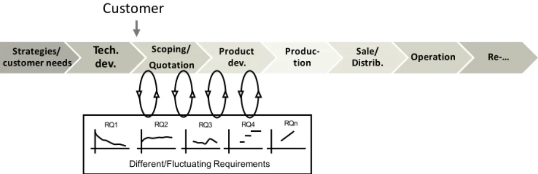
This especially applies to companies developing and manufacturing highly customised products as suppliers. The traditional view of the product lifecycle introduces the customer during the sale and distribution stage (Figure 1). This type of business is often concerned with identifying and transferring customer needs into fixed specifications that guide the product development (PD) of end-consumer products. However, suppliers with an engineer-to-order (ETO) custom-isation strategy differ in that the customer is already involved by the scoping and quotation stage (Figure 2).
These companies cannot work as the former type since the customer, often an original equip-ment manufacturer (OEM), directly sets the requireequip-ments. It is not uncommon that products are developed in cooperation with the customer, often an OEM or another supplier; that projects are run for several years and that requirements are not fixed at the outset. During the cooperative development stage, requirements often change. These changes have many sources (Fernandes et al. 2015), but they often stem from the complex interplay between the involved suppliers that are using the same interfaces as references for their own development process. When a solution requires change to shared interfaces, other suppliers’ solutions are affected. This requires change from affected sub-systems or changes to the requirements themselves. On these occa-sions, it is crucial to manage these requirement fluctuations and have a way to adapt to such ever-evolving situations.
Customisation refers to the ability to design and manufacture tailored products for individual customers. Four different business models can be identified depending on where the actual cus-tomisation starts: ETO, modify-to-order, configure-to-order and select variant (Hansen 2003). In the latter two, product platforms have been successful enablers of efficient customisation through, for example, modularisation. One factor that amplifies the challenge for the suppliers is the separating of technology development (TD) and PD. TD often has a longer-term goal of supplying to some extent an uncertain future market with new technology, whereas PD is of a more short-term character and fulfils specific customer requirements.
Strategies/
customer needs Tech. dev. Product dev. Produc-tion Distrib.Sale/ Operation Re-…
Customer
Figure 1 End consumer (customer) involvement in the product lifecycle
Strategies/
customer needs Tech. dev.
Scoping/ Quotation
Product
dev. Produc-tion Distrib.Sale/ Operation Re-…
RQ1 RQ2 RQ3 RQ4 RQn
Different/Fluctuating Requirements
Customer
Platform strategies as enablers for customisation have been widely accepted in the industry; they serve a wide variety of products while keeping internal variety low (Meyer and Lehnerd 1997). Platforms have also been a way to effectively reach different customer segments while maintaining commonality in product components and interfaces. Here, balancing the trade-off between commonality and distinctiveness is key to success (Halman, Hofer, and Vuuren 2003). Recent research has focused on platforms with a broader scope regarding definitions which aim to reuse more of the skills and knowledge (i.e. assets) that are created in a company. From this perspective, Joahannesson (2014) questioned whether companies could afford not to apply a platform. However, how to apply a platform strategy for ETO suppliers, where interface stand-ardisation and component commonality are hard or impossible to take advantage of, has not been fully investigated. Component-oriented product platforms tend to require focused platform development and late-stage customer involvement, which in turn requires some knowledge about which future variants are to be derived from the platform. This kind of forecast is hard or impossible for ETO suppliers, whose main competitive edge lies in a high level of customisa-tion and where the interfaces with the customer product are unknown beforehand.
This article is part of the outcome of a three-year research project conducted in cooperation with four industrial companies engaged in the development of highly customised products. The aim of the research was to make companies acting as suppliers and developers of highly cus-tomised products more responsive to changing requirements that arise during the development process. This article investigates the current state of four ETO companies regarding platforms as a means of conducting efficient customisation. It proposes a platform approach to make it possible for these companies to benefit from the efficiency that platforms can accommodate. The academic contribution consists of adding to the body of knowledge regarding platform modelling, definitions and scope. The industrial contribution consists of applying and support-ing the proposed definition to enable companies to engage in platform-based development.
Methodology
This article describes a study that employed and mixed several different research methods. The main research framework used for the project was the design research methodology (DRM) proposed by Blessing and Chakrabarti (2009). All four stages were completed once, including a loop back of the last two stages. The following summarizes how each stage was conducted and what methods were used.
(1) Research clarification (RC). This was completed by studying the previous literature and elaborating on the research gaps.
(2) Descriptive study I (DS-I). This was performed by conducting a set of semi-structured in-terviews and reviewing company documents at the companies leading up to state-of-prac-tice descriptions and ‘to be’ descriptions. A workshop session was used to identify success criteria (SC) and their associated measurable indicators as a datum for evaluating the solu-tions further on. The SC are further introduced in connection to the evaluation (Table 2). (3) Prescriptive study (PS). This is characterised by its explorative nature, bringing in
ele-ments from both action research and systems development. The stage was conducted at two levels: the generic level and the case level. The generic level focused on synthesising the generic platform model. The case level dealt with the development, introduction and verification of support to realise the generic model in three of the cases.
(4) Descriptive study II (DS-II). This was conducted twice and resulted in two sets of case evaluations and one final evaluation of the complete generic platform model. The first set of case evaluations was used as a status check in each case to evaluate the project progres-sion; it is further described in (André, Stolt, and Elgh 2016; Heikkinen, Johansson, and Elgh 2016; Stolt et al. 2016). The second set of case evaluations and the final evaluation were conducted using self-administered questionnaires.
Frame of Reference
An important aspect of customisation is the ability to manage requirements, and a great deal of research has been done in the areas of consumer products (Jiao and Chen 2006) and configura-tions systems (Hvam, Pape, and Nielsen 2006). However, the prerequisites of customising for an end consumer compared to an OEM are different, causing various methods to be used in past research. Suppliers of ETO products are often required to stretch the boundary of every new PD project, which forces them into new territory regarding designs and the way they conduct design. Elgh and Cederfeldt (2008) used a process approach for ETO companies to assess pro-ducibility by proposing a cost model and propro-ducibility rules under the effect of changing re-quirements. Reasons for changes in requirements include incomplete capture, traceability is-sues, customer-driven changes, incorrect or ambiguous language, missing requirements and re-dundancy (Fernandes et al. 2015). Although attempts have been made to propose standardisa-tion for ETO companies (Vollmar and Gepp 2015), the presented reasons contribute to the chal-lenge of creating a component-based platform with standardised interfaces for ETO suppliers. Like standardisation, design reuse has been coined as a passable way for ETO companies to succeed in the process of designing customised products. Brière-Côté, Rivest and Desrochers (2010) proposed a support method to incorporate emerging solutions in a generic product struc-ture as a way of increasing design reuse in ETO companies. They used functional, technological and physical levels of abstraction. Baxter (2007) considered knowledge to be actionable infor-mation and problematised the fact that many previous design knowledge reuse systems exclu-sively focused on geometrical data, which is often not applicable in the early stages of devel-opment. Future reuse models need to contain problem-solving methods, solution generation strategies, design intent and project knowledge. Baxter (2007) introduced a support tool to in-crease the possibilities of design reuse that utilised both a process and a product view. Knowledge-based engineering (KBE) has been pointed out as an enabler for mass customisa-tion as a way to manage large ranges of variant designs as well as respond quickly to customer requirements. KBE, however, needs to be further researched in order to, for example, develop methodological support, improve transparency and efficiently source and reuse knowledge (Verhagen et al. 2012). Stokes (2001) presented a complete framework and a detailed method-ology, called MOKA – methodology and software tools oriented to knowledge-based engineer-ing applications, that collected and formalised knowledge to create knowledge-based systems. Here, the knowledge was gathered from domain experts using standard templates, called ICARE forms, which created an informal model.
Past research has focused significantly on company and customer integration and collaboration (Tuli and Shankar 2015). The focus has often concerned a single interface (Siddique and Boddu 2004), which in many cases is a simplification of reality. Suppliers with an ETO business ap-proach are often part of a supply chain where other suppliers and an OEM act in between them
and the end customer. This introduces several interfaces and stakeholder interests that the sup-plier must manage. Holistic research in this area taking several or all of these perspectives into consideration is scarce. (Tuli and Shankar 2015) described lean in collaboration between sup-pliers and OEMs and reviewed existing literature on supplier, OEM and customer integration. One interface toward the customer that is central to customisation is the customer order decou-pling point (CODP). This is normally defined as the point in the flow of goods where forecast-driven production and customer order-forecast-driven production are separated (Giesberts and Tang 1992). Wikner and Rudberg (2005) proposed a two-dimensional CODP categorisation for com-panies in the midst of the product realisation process which both takes an engineering and a production dimension into consideration and thus covers a larger space of customisation strat-egies than what previous categorisations have.
Platform models and methods
The definitions of what a platform is or could be span a notable space. The most used and applied definition focuses on tangible things and was formulated by Meyer and Lehnerd (1997) as ‘A set of common components, modules, or parts from which a stream of derivative products can be efficiently developed and launched’. A more abstract definition by Robertson and Ulrich (1998) is ‘The collection of assets [i.e., components, processes, knowledge, people and rela-tionships] that are shared by a set of products’. Other available definitions usually fit some-where in between these two. Halman, Hofer and Vuuren (2003) argued that companies were not keeping pace with research on platforms due to a lack of tools. The same authors described a differentiated view of platforms in industry that could be explained by the span of definitions in existence. One risk with using a product platform approach is the trade-off between com-monality and distinctiveness (Robertson and Ulrich 1998). Another trade-off is between in-creased development efforts for the initial platform and the uncertainty of whether the right platform has been chosen in order to develop a sufficient number of derivatives to gain back the extra expenses (Halman, Hofer, and Vuuren 2003).
Although not much research has been conducted on platform application in ETO supplier com-panies, Högman et al. (2009) investigated a platform formulation for a supplier with a small-batch production. The authors found that a modular platform was infeasible in such a company and that the possibility of reuse existed on a higher level of abstraction. Kristianto, Helo, and Jiao (2015) propose a system level configurator directed to ETO companies developing large complex products, involving suppliers with development of their own. The authors propose that system level configuration should maintain the key building blocks and possible interfaces be-tween components. This is managed using templates. Each supplier can then provide their building block for the complete design. Cooper (2006) suggested that one deliverable from technology development was a technology platform. This was further investigated by Högman et al. (2009), who presented a technology platform definition that was not connected to a spe-cific implementation but rather consisted of design knowledge, product concepts, applied tech-nology and technological capabilities in order to support product realisation. Levandowski, Jiao and Johannesson (2015) proposed a two-stage model of an adaptive product platform as a means of managing changing requirements during development. In the first stage, modules were pre-liminarily configured and high-level decisions were made. In the second stage, scalable param-eters were adapted when requirements were stabilised.
A platform model can be used to describe its abilities. The product variant master (PVM) is a tool that can to some extent be used to model a product platform (Hvam, Pape, and Nielsen 2006). The main aim of the PVM is to map a company variant flora and couple it to a generic product structure to create a foundation for introducing configuration systems. Another meth-odology that can be described as a platform model is the configurable component (CC) concept (Claesson, Rosvall, and Johannesson 2005). Instead of modelling the connections between physical parts and modules as in the PVM, the connection from functional requirement to de-sign solution is mapped. Otto et al. (2016) proposed a generic 13-step process for dede-signing product platforms. The 13 generic design steps are associated with platform development meth-ods used in several industrial companies. Li et al. (2013) presented an approach for flexible platform development using flow analysis, DSM, multidimensional scaling and fuzzy cluster-ing, which is used to identify modules. Another approach that integrates quality function de-ployment as a means to not only develop a modular product platform, but also as a way to understand the product family was presented by Park et al. (2008). Their method included cat-egorising technical requirements and calculating the degree of variety among components.
Summary and research opportunity
The body of knowledge in the area of product platforms is vast, and many examples of success-ful implementation of a platform strategy based on a modular product architecture by OEMs exist. There is, however, a lack of research describing how ETO suppliers can benefit from platform development. Their business model simply does not allow a limitation of the product offer that component-oriented product platforms demand. The separating of TD and PD also adds to the issue of applying a platform approach due to the challenge of developing the right platform for future variants. The summary also points to attempts (Högman et al. 2009) to de-scribe a more abstract definition of a product platform that goes beyond components (Robertson and Ulrich 1998). There are a lack of models, methods and tools that support the creation and application of a platform approach that utilises assets other than the traditional components and modules. The identified research gap concerns a model and support that enables a structured way of managing development assets for ETO suppliers that further supports them to conduct platform-based development to become more efficient when customising product variants.
Exploring the needs and practices of platforms in four ETO companies
Four companies were studied to gain a deeper understanding of PD and the current use of plat-forms as well as the need for improved support in ETO-oriented suppliers. During the interview portion of the study, the companies (see Table 1) were asked general questions about their PD processes and their use of platforms. Three to four people from each company were inter-viewed; they represented functions like design engineer, project manager and engineering man-ager. The interviews are summarised in Section 3.1. Then, workshops were conducted with all the companies investigating what descriptions, for example tools and methods, that could help them improve their work when facing fluctuating requirements. These workshops involved two people from each company (the results are summarised in Section 3.2).
Product development and the use of platforms
C1: The development model was a standard gate model containing four stages. The PD
pro-cess included a reflective stage where knowledge briefs (k-briefs), lessons learned, prob-lems and inventions were developed. Trade-off curves showing the relations between im-portant design parameters were used to answer quotations from customers. A finished product variant was controlled by the top assembly with underlying articles in the PDM environment.
C2: The PD process for C2 was a traditional development process containing five steps. The
reusable assets were made from the designers’ know-how, modules and components used for manufacturing the customised machines. Experience was passed on through different documents (e.g. computer aided design (CAD) files).
C3: Four different project types existed to support PD at C3 with different numbers of gates.
The reusable assets at C3 were realised through modules and shared components. C3 had policies for capturing the experiences in several documents, but information still got lost. Lessons learned were used to store the main issues that had been noted during the project such as problems, obstacles and tips for future projects.
C4: C4 used a gated process for PD with two main parts: ‘plan product’ and ‘develop product’.
The company used three different platforms: a technology platform, a product platform and a manufacturing platform, all of which were extensively defined. C4 viewed a plat-form as an explanation model that contained a set of rules and standardised methods for use in the development process. The platform had no other versions, was not made of physical components and was continuously evolving.
Abilities and descriptions to support adaptability
This section summarises the results of the workshops investigating the companies’ abilities and what descriptions that support the customisation of adaptable technology solutions. The two following questions were asked and the respondents gave their answers individually followed by discussions:
• What would increase your ability to continuously manage changing
and conflicting requirements when developing customised products?
C1: Better access and knowledge about product data internally to get measurements, estimate
cost, access trade-offs, determine the cost for each article and determine what has been done before.
C2: To have clarity around concepts, terms and requirements and to find out what has been
done before. To have clear communication with the customer and identifying what re-quirements that are highly likely to change. To increase the general understanding of what changed requirements implies (e.g. cost and time).
C3: Use parallel solutions and concepts. Utilise efficient ways to estimate costs. Early
in-volvement of the right competencies. Increase the number of variants. Access and visu-alise trade-offs.
C4: Being able to describe adaptability in new technologies and to develop adaptive
technol-ogy solutions that can handle scalability. Methods to visualise the effects of fluctuating requirements as a means of questioning and evaluating conflicting requirements with the customer. Early evaluation of producibility.
• What descriptions can support the work of customising adaptive technology solutions?
C1: Graphical presentations, descriptions of standards, problem and solution descriptions that
are coupled with the product, visualisation of the product or component, access to de-scriptions of performance and FEM calculations.
C2: Design rationale.
C3: Simulations validated through test results, CAD files, bill-of-material (BOM), generic
product structure, prototypes, product cost calculations and analyses to track costs.
C4: Extending the product model with adaptivity to be handed over from TD to PD in order
to describe the possibility for adaptation of the technology.
The outlook of a coherent platform description
Only one company (C4) used the term ‘platform’ internally. For the others, the research team identified platform constructs and their relations. The main conclusion was that development assets already existed in these companies (e.g. tools and designs); they could be integrated and improved, and when combined with additional constructs, they could form a coherent platform description to be used in PD. From the first question that was asked to the case companies, it can be concluded that there are many ways to increase the ability to manage fluctuating require-ments. The answers to the second question show that the descriptions that are used and could be used for this purpose are many and diverse. In order to work in a platform-based way, these ways of working and describing solutions need to be supported by suitable tools and methods.
A coherent platform description of heterogeneous assets
Manufacturing equipment like machines and tools as well as standardised manufacturing pro-cesses are a necessity in manufacturing companies. It is common practice to keep track of which machines there are, their capabilities, what activities they can perform and the cost of using them. This can be referred to as a manufacturing platform that enables the production of certain product variants. Development resources can be thought of and described in a similar manner as important assets – they are investments made in the company. However, the capabilities of the development team and what solutions and tools exist are less often described in a coherent way. The platform model, as will be outlined, aims to partly be this description as a coherent model bringing together elements of platform theory and other kinds of resources residing in companies. The platform model should host adaptable solutions to enable efficient customisa-tion at a later stage. In order for companies to build an ability to create such platforms, it is important to acknowledge that changes will occur throughout the development and that a set-based (SB) approach should be applied to create the adaptability to respond to the change
(Raudberget et al. 2015). An SB approach focuses on defining and narrowing design spaces in which requirements can be allowed to vary.
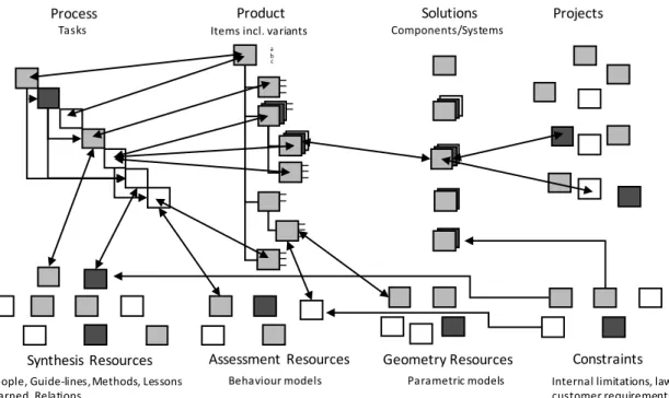
The DP model is grounded in the platform definition by Robertson (1998): a product platform to be constituted by assets residing in the company. What needs to be added to this definition is a coherent description or model that makes use of these assets in the right way. Without a coherent platform model, and with just a vague definition of what a platform is, the develop-ment will not be supported. A specific DP is composed of different objects related to processes, synthesis resources, product constructs, assessments resources, solutions and projects. These domains are the result of the workshops with the participating companies and the fact that the design is commonly divided in both the synthesis and assessment stages (Cederfeldt 2005). The domains should support pre-existing resources in a company (commonly, projects and solution resources) as well as describe generic processes, generic product concepts, tools and future support models. An image describing an example of the information model on a conceptual level is included in Figure 3.
It illustrates that these different objects are linked to a generic product concept and process. Though a company business model might not allow for a traditional product platform approach, elements of knowledge regarding the product concept often exist that can be a mix of methods, tools, standard components, etc. Some parts of the product might have the potential to be stand-ardised whilst others require that specific processes be completed during the design process, resulting in unique parts. Therefore, both a product and a process domain are included and linked to each other. For example, a component type that often requires a unique solution can be supported by and linked to a formalised process model that is in turn linked to design guide-lines (synthesis resources); these support the determining of specific parameters and calculation models (assessment resources), which support the assessment of parameters or complete de-signs. These are linked to relevant constraints that should be considered during the process. Modelling the processes, product concepts and resources essentially brings knowledge together and enables reuse, which supports designers by creating a toolbox of designs and means for
Figure 3 The DP and its main construct types
Solutions Process Tasks Components/Systems a b c
People, Guide-lines, Methods, Lessons learned, Relations
Product
Items incl. variants
Projects
Parametric models Behaviour models
Assessment Resources
Synthesis Resources Geometry Resources
Internal limitations, law, customer requirements
design. Figure 4 shows a generic unified modelling language (UML) diagram as a formal rep-resentation of Figure 3. The information model is ultimately realised in a PDM environment, with the objects containing metadata pointing to the location of specific files that contain de-tailed information on the object. The dede-tailed information can also be encapsulated in the object itself depending on the specific implementation of the DP.
The generic representation of the product is referred to as generic product item (GPI) and rep-resented by the class GenericProductItem. Each object that is instantiated from this class be-comes a variant and will be unique to a specific project; it consists of its generic structure, cardinality and attributes. The GenericProductItem has the property TopPart, which can be one of two types: Assembly or Component. Assembly refers to a set of Component and/or Assembly objects. The decision of what type of Part the TopPart will be depends on the type of product that is modelled and the associated business model of the company. If the GenericProductItem contains a structure, the TopPart will be the topmost Assembly. In contrast, if the structure is implicit and merely the result of the development process, the TopPart is better suited to being classed as a Component. The Assembly and Component classes can thus be seen as place mark-ers for intended or needed resources to support their realisation and not as solutions themselves. The class Part has a list of the Construct class. The Construct is the general type of class that is used to model and point to resources of different kinds. The Construct class contains attributes which describe the following:
• Description, which is a general explanation of what the Construct is and does • Information about when and in what context the construct is valid
• The technology readiness level (TRL), which denotes the maturity of the construct. This number ranges from 1–9 and originates from the aerospace industry (Mankins 1995). A 1 implies that basic principles have been observed and reported, and a 9 refers to a fully developed and validated con-struct. The TRL is used to judge which constructs need further development and which constructs can be used as they are.
• Management and responsibility information including relevant people, dates and versions
• Information regarding the raw data and their location for the detailed information that makes up the construct
Part
Assembly
Assemblies : List of Assembly Part : List of Part GenericProductItem TopPart: Part Project : String Construct 1 0 ..* 0 ..* 0 ..* Constructs TopPart Parts Assemblies DesignPlatformObject Name : String Clone GeometryResource
ProcessResource SolutionResource SynthesisResource AssessmentResource
ID : Integer Constructs : List of Construct
Project Component 0 ..* 0 ..* 0 ..* Constraints Constraint
The different classes that inherit Construct include ProcessResource, SolutionResource, Syn-thesisResource, AssessmentResource, GeometryResource and Project. These are differentiated depending on the needs of the specific company where the DP model is applied. The Constraint class inherits Construct, but it can also be a part of SolutionResource, SynthesisResource and AssessmentResource. Objects instantiated from SolutionResource relate to finished designs that have formally been designed and have thus been created with some boundaries as defined by Constraint objects. SynthesisResource has explicit Constraints that are related to the method, guideline or tool that the object represents. Objects of the type AssessmentResource support the evaluation of product variants and embody mathematical models representing behaviour and other properties. They have implicit Constraints, the implications of which are made visible through, for example, simulation models. A ProcessResource can be in the form of tasks or execution orders of activities that are required or intended to support some part of the design process. Objects of the type GeometryResource are commonly parametric CAD models that can act as a baseline for new designs. Their parametric nature can, in turn, represent the physical design space of the model.
Design platform use
The platform utilisation is divided into two stages: expansion and use. The first refers to when the model is established or modified; here, descriptions are created and relevant information is linked to the model. The use stage refers to when the information in the model is used and DP variants are created. A DP variant is a description of the finished product design, the resources used during the design process and the relation between them.
The use of the DP requires that some knowledge has been modelled using the DP. Using the platform focuses on the creation of specific instances that are developed for specific customers. When a quotation process is initiated or an order project begins, the model is used to get a first glimpse of what information exists and what does not. The first step is to search GPIs in order to determine if a similar system structure or component has been created in the past. If such a structure or component exists and fits with the specification, the associated variants of that GPI can be searched and matched to the customer’s requirements (constraints). However, in most cases, there will be no complete finished variant design. This is common for the components and systems that interface with the OEM product and where subjective requirements are com-mon. In these cases, there are often associations with a formalised process with links to other resources describing, for example, a task, a parametric CAD model or calculation spreadsheets that aid in designing the desired component or sub-system.
When the search has been completed, the model is ready to be instantiated. Upon instantiation, a variant is created that represents an unfinished DP instance. It consists of resources to support its realisation which are used in the following design process. In special cases, no product struc-ture will be identified when modelling the DP – here, the strucstruc-ture is implicit and is the result of the design process. This is common for manufacturers of highly customised manufacturing equipment where no product concept exists beyond the component and sub-system level. In this case, tasks and guidelines are suitable for governing the work of specifying the final product structure.
During the PD, the variant is continually updated and the different Component and Assembly levels are associated with the created designs and resources used in the process. In this way, the
GPI and the complete platform evolve as new knowledge is described, added and associated. When a project is finished, one of the outcomes will be a DP variant that will partially act as the design rationale. In upcoming projects, these variants will be found during the initial search and include an overview of what, how and why the design is designed the way it is.
Design platform expansion
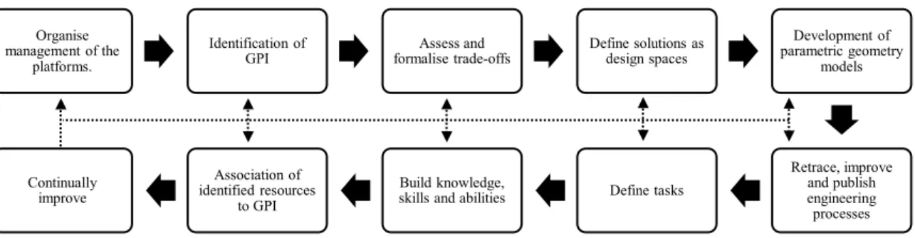
Companies offering a high level of customisation often have an identified product concept con-sisting of items occupying different levels of realisation. Knowledge and experience are also part of the product concept that supports designing specific variants. The DP allows for model-ling these items on a generic level and associating them with existing solutions or other re-sources that support their realisation. The activities that support the definition and expansion of the DP model are shown in Figure 5.
Organisation and management of the platforms need to be set up early in the process of defining a DP. This step refers to pointing out areas of responsibilities and associated personnel. The next step is to formalise and generalise the product concept by identifying the GPIs. These are the common bases to which different constructs and descriptions can be linked. These items might not correspond to a pre-existing design; however, they must be included in the finished design. When the GPIs have been identified, generalised trade-offs associated with the GPIs needs to be assessed as part of the SB approach. These concern properties in existing designs and concepts that are related to each other (e.g. weight vs tensile strength) that are known from previous experience or simulations. Also, part of the SB approach is defining continuous or discrete sets and spaces in the creation of new designs. By identifying and modelling the feasi-ble parameter space of a design, variations of such designs can be reused and cover a larger application area. To support the modelling of these design spaces, geometric models are devel-oped by identifying generic characteristics of existing geometry and trends in geometry adap-tation. Processes, best practice methods, guidelines and tools for their completion are retraced, modelled and published. These are described using standard classes. Competence teams are established to build and preserve knowledge, skills and abilities. The GPIs are then linked to the identified descriptions, models and other resources needed for their realisation. Improve-ments through the experience and knowledge gained from PD is continually assessed and ap-plied when a sufficient level of maturity is reached. This can be achieved using lessons learned, which helps users to identify issues in their current way of working or in the resources they have used. Action plans can then be created to address the identified issues and to implement the improvements. New formats can also be introduced that capture the specific types of infor-mation needed in the PD.
Organise management of the
platforms.
Identification of
GPI formalise trade-offsAssess and Define solutions as design spaces
Development of parametric geometry models Retrace, improve and publish engineering processes Define tasks Build knowledge, skills and abilities Association of
identified resources to GPI Continually
improve
Applying the design platform in four cases
The DP model was developed in cooperation with four companies. This section presents how the DP was conceptually modelled in the companies by identifying existing and future resources that have the potential to be mapped to the model. Support was also developed in C1, C3 and C4 with the intention of further aiding the introduction of the DP and adding to its usefulness. The tools developed to support the application of the DP in the cases either concerned the ad-dition of a specific resource type, the creation of a coherent DP model or both. The focus was placed on C1 to exemplify how the DP was modelled and applied. C2, C3 and C4 were not described and exemplified in the same level of detail and were used to strengthen the validity and utility of the DP.
C1
The DP model was introduced and applied to C1, a second-tier supplier in the automotive in-dustry. The application of the DP model concerned a business area where the company devel-oped and manufactured a pneumatic seat support system to increase the comfort and ergonom-ics of the user’s back. The company was in principle willing to customise or redesign each part of the system if required in order to not lose business; it was, however, desirable to reuse as much as possible from previous designs and previously created knowledge. Due to the high level of customisation that was offered, the speed and accuracy in the quotation process were an issue. Speed was important to quickly return an offer to the customer, whereas accuracy was of importance to charge the right price. It was therefore vital to reuse as much of the already developed assets as possible, placing a high demand on finding the needed information and judging its applicability.
The DP model was used to create a conceptual model of the different identified resource types. A visualisation of the mapping between existing and future resources can be seen in Figure 6. The figure also points to where the effort was focused during the project. In the beginning of the project, the company had a mapping between projects and solutions using a traditional file structure in its PDM system. It also made attempts to describe some of the know-how regarding the process and product knowledge using standard templates. These were, however, unstruc-tured and were not used to a greater extent. No detailed formalised processes existed and thus no specific support was used during development.
Forming the DP was part of the expansion stage and was supported by the guidelines and pro-cess proposed in Figure 5. As a result, a group consisting of two researchers and three company representatives was created to oversee the DP. The identification of GPI followed and was per-formed using PVM (Hvam, Pape, and Nielsen 2006). An array of previously designed products was reviewed, resulting in the identification of six initial GPIs that represented complete system assemblies. The six GPIs spanned system functionality from simple static lumbar support to an advanced massage system and could be seen as the common denominators between the re-viewed products. The next six steps (Figure 5) were performed in an iterative manner by intro-ducing design elements (DEs). The DEs were inspired by the MOKA methodology (Stokes 2001) and are explained below. Examples that were captured and modelled are similarly exem-plified in connection to each type:
• Activity (tasks and process models containing execution orders, input, output, triggers and objec-tive):
- Quotation process. The steps of the quotation process were identified and formalised.
- Pre-configuration of components. This was done early to produce a prototype in the quotation stage.
- Commonality check. Systems that were developed concurrently were checked to find possi-bilities for component sharing.
- Define system architecture. Based on what functionality the customers asked for, a principal architecture was sketched featuring solution types and functionality.
• Entity (existing components and systems described by function, behaviour and links to geometry models):
- Three different pumps were identified to which small adaptations were made for each cus-tomer.
- Four different valves were identified that were either used for massage or static support. These had different properties depending on performance and functionality.
- Several air cells were identified. These were specific for each customer since seat geometry varied heavily between customers.
• Rule (guidelines and relations in the form of mathematical formulas, tables, text or figures): - Air cell material choice guidelines
- Air cell material thickness guidelines
- Lumbar air cell restrictor design. To achieve different shapes during air cell inflation, restric-tors could be welded onto the air cell.
The DEs were standalone objects that could be reused and applied to different items; they were created using spreadsheet templates. Similarly, constraints were captured and resulted in DEs describing limitations in manufacturing equipment, specific customer requirements, environ-mental requirements and laws to be considered. In total, about 100 DEs were identified and created and since some of them are reused in several GPIs, the number of relations (associa-tions) is much more. Essentially, the information needed to form the DEs and constraints was gathered from interviewing designers and reviewing documents. DEs offer a way to describe finished designs, trade-off curves, design spaces, engineering processes, tasks as well as build-ing knowledge, skills and abilities. The DEs were ultimately a way to add resource objects in the categories of ProcessResource, SolutionResource, SynthesisResource and Constraint. The relation between the DEs and the generic information model is shown in Figure 7.
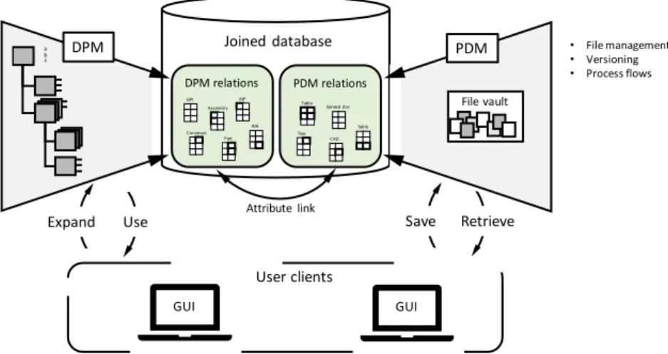
A support application was developed as an extension to the PDM system currently used in the company to facilitate modelling the DEs, GPIs and to be able to associate the two. The appli-cation featured functionality that allowed the user to create GPIs, couple DEs and other re-sources to the different levels in the GPIs and the instantiation of variants. The model that was created using DPM was saved directly in, and could be linked to the content of the PDM system database, which minimised data redundancy and enabled multi user and concurrent usage. The PDM system focused on file management, keeping track of versions, metadata and process flows, whereas DPM focused on offering a coherent view of the resources that were part of the platform and were used to create variants. The principal architecture of DPM is shown in Figure 8.
Use follows the expansion stage, and in this case, refers to when DPM is employed in the be-ginning and during a development project. When a quotation arrived at the company or when requirements changed during development, DPM was used to gain an overview of which GPI corresponded to the request for quotation (RFQ) requirements. Processes were also available to
guide the project team through the quotation and design process. Variants that were instantiated from a certain GPI could then be reviewed and compared to the customer requirements. For some structural levels, there were existing solutions that could be used (e.g. pumps, valves and tubes). For other levels (e.g. air cells and adaptors), however, no solutions corresponded to the requirements and therefore had to be designed from scratch. In these cases, DEs were useful to describe tools and to design guidelines of specific parameters and constraints that needed to be considered. These were used during the design stage. As new knowledge emerged, the DEs improved and new DEs were created and associated with the GPIs and variants, which ulti-mately created an evolving platform of design assets to be used in PD.
C2
C2 provided automation services, robotic solutions and special products to the manufacturing industry. The company had several fields of expertise, including consulting and in-house PD, making it able to offer an ‘all-inclusive’ service where the products and related production equipment were developed. A file structure in the company PDM system provided a mapping between solutions and project. C2 also had a tool for searching for existing candidate solutions to support reuse. The future objective was to further support PD by developing synthesis, assessment and geometry resources as well as constraints together with descriptions of product constructs and tasks; however, the latter two were unstructured since the final products were
Save Retrieve Expand Use Joined database DPM relations PDM relations GPI Construct Part Assembly AtA AtP Tree CAD Table Table General doc a b c DPM • File management • Versioning • Process flows Attribute link User clients PDM File vault GUI GUI
Figure 6 The conceptual mapping of development resources in the DP for company C1
Solutions Manual Process Tasks Components/Systems a b c
People, Guide-lines, Methods, Lessons learned, Relations
Product
Items incl. variants Projects
Parametric models Behaviour models
Assessment Resources
Synthesis Resources Geometry Resources
Internal limitations, law, customer requirements Implemented pre research
project Support introduced during research project Future Constraints
Figure 7 The addition of DE classes in the generic in-formation model Entity Supplier : String Activity Input : String Functions : String Behaviour : String Output : String Trigger : String Objective : String Rule Input : String Output : String Objectives : String Part Assembly Assemblies : List of Assembly Part : List of Part GenericProductItem TopPart: Part Project : String Construct 1 0 ..* 0 ..* 0 ..* Constructs TopPart Parts Assemblies DesignPlatformObject Name : String Clone GeometryResource ProcessResource SolutionResource SynthesisResource AssessmentResource
ID : Integer Constructs : List of Construct
Project Component 0 ..* 0 ..* 0 ..* Constraint 0 ..* Objective : String Test : String
unique. The conceptual DP model was created and used to map the current state of C2 (shown in Figure 9).
The company experienced issues with fluctuating requirements during development as well the challenge of working in a platform-based way due to the uniqueness of each product variant. Due to its point-based approach during development, solutions were seldom described in a manner supporting reuse. Few or no strategies existed for retracing and publishing engineering processes and tasks. Building knowledge, skills and abilities were mostly at the individual level and was not spread out among the engineers. C2 needed a way to tie the development assets together in order to be able to work in a platform-based fashion to a higher degree. Increases in the use of the different assets by using suitable formats were also essential.
C3
C3 was part of the automotive industry, supplying solutions for attaching equipment such as bicycles, kayaks and skies onto automobiles. The company worked both directly for consumers with aftermarket products as well as for car manufacturers as an original equipment supplier. This case focused on the aftermarket products. As new car models emerge, the solutions are adapted to fit the new models. C3 had a synthesis and solution resource to support finding similar existing components and a general product structure. Geometry resources such as para-metric CAD models existed if new designs needed to be defined. Other resources existed to some extent, which is shown conceptually in Figure 10.
Due to the increase in car models and the speed with which these enter the market, the devel-opment of C3’s products needed to be quicker in order to stay competitive. The application of the DP model focused on the addition of an assessment resource in order to streamline the simulation process of an essential component of the product that was adapted for every new car. A simplified version of the adaptation process can be seen in Figure 11, which also points out which components were adapted. When entering a new development project, the car roof was an unknown at the outset. This stressed the need to adapt the two interfacing components: the footpad and the bracket. One obstacle when doing these adaptations was predicting their
Figure 9 The conceptual mapping of development resources in the DP for company C2 Solutions Unstructured Process Tasks Components/Systems a b c
People, Guide-lines, Methods, Lessons learned, Relations
Unstructured Product concept
Items incl. variants Projects
Parametric models Behaviour models
Assessment Resources
Synthesis Resources Geometry Resources
Internal limitations, law, customer requirements
Implemented pre research project Future
behaviour in a crash. The simulations needed to predict whether a proposed design would pass the crash regulations were complex, involving not only the product itself, but also the car roof.
To set up the simulations required expert work and took up to 14 days due to the many simula-tion models in line. However, software was developed within the project and was introduced to the company’s CAD and FEA systems, showing that it was possible to partially automate the process, shortening the time it took to make the evaluation. The design engineers could operate the system since the calculation engineer’s knowledge concerning how a CAD model should be turned into a FEM model was added to the CAD software. The system was designed for a special type of roof rack where a basic design could be adapted to various car models. This was done by customising a pad and a bracket that interfaced with the roof. The complexity of the simulations included large deformations which made it necessary to create structured meshes. The system identified the different components in the CAD models and then found lower-level elements in them so that the structured meshes could be created in the FEA system using ex-truding, revolving or sweeping. A FEA model could be solved on a powerful computer cluster in 30 hours, resulting in a prediction of whether the proposed design would pass the regulations for road safety or not. This made it possible to enlarge the set of designs under consideration, adding to the ability to quickly respond to requests for changing requirements in aspects other than crash regulations. Revisiting Figure 5, constructing the prototype system involved formal-ising the calculation engineers’ way of working in terms of process and setting up the simulation
Figure 10 The conceptual mapping of development resources in the DP for company C3 Solutions Semi-automated Process Tasks Components/Systems a b c
People, Guide-lines, Methods, Lessons learned, Relations
Product
Items incl. variants
Projects
Parametric models Behaviour models
Assessment Resources
Synthesis Resources Geometry Resources
Internal limitations, law, customer requirements
Constraints
Implemented pre research
project Support introduced during research project Future
Figure 11 The simplified adaptation process of C3 and what components that are adapted
Profitable?
Start End
Yes
Scoping Scan Roof Roof Data Search Existing Matching Components No Exist? Design New Components No Prototypes Yes Crash Simulations Ok? No Yes Tooling,…. Packaging Etc………... Bracket
model. This formalised knowledge was then made available in the CAD environment for use by the design engineers. The introduced support increased their abilities to evaluate larger de-sign spaces, investigate trade-offs and build new knowledge and skills. Organisation and sponsibilities regarding the platform remained to be established along with associating re-sources with GPIs.
C4
C4 supplied components to aircraft engines. Its development projects were conducted in col-laboration with the aircraft engine manufacturer and extended for long periods of time. The components had extreme requirements regarding performance and weight, requiring cutting-edge materials and manufacturing processes. The company made extensive analyses in the early conceptual stages using an environment consisting of several commercial and in-house developed software applications that were integrated. C4 had synthesis, assessment and geom-etry resources together with descriptions of structured product constructs and tasks organised in an automatically executed process. The mapping of these can be seen in Figure 12. How-ever, most of the platform was only used pre-sales for scoping and learning activities.
In new generations of aircraft engines, the demands on weight, thrust, fuel consumption, service life and noise level are increasing. Further, the number of aircraft that is manufactured is rising, placing demands on the efficient manufacturing of the products. The CAE environment used for extensive analyses in the early conceptual stages combined parametric CAD with, for ex-ample, FEA, CFD and rule-based evaluation. Conceptual designs were proposed in the early stages of development; they were evaluated in the CAE environment. The motivation was to build knowledge and to understand the trade-offs in the conceptual design. The evaluation was done using an automated process so that hundreds of different geometrical variants of the con-cept could be generated and evaluated for structural strength, aerodynamics, lifetime, etc. A simplified version of the automated CAE environment process is shown in Figure 13. Through these experiments, knowledge was gained on how the geometrical parameters (lengths, angles, number of vanes, etc.) affected engine performance. This enabled the company to gain an
over-Figure 12 The conceptual mapping of development resources in the DP for company C4 Solutions Automated Process Tasks Components/Systems a b c
People, Guide-lines, Methods, Lessons learned, Relations
Product
Items incl. variants Projects
Parametric models Behaviour models
Assessment Resources
Synthesis Resources Geometry Resources
Internal limitations, law, customer requirements Constraints
Implemented pre research
view of what sets of requirements could be met so that it could assist its customers in formulat-ing the requirement specifications. It also made the company responsive to customer bespoke changes. Questions of the type ‘What if…?’ could readily be answered. In the case studied, the capability of the CAE environment was extended via an assessment resource that evaluated manufacturability in terms of robotic welding. For each variant, the evaluations concerned the following:
• The possibility to access and inspect the welds
• Whether the material thickness was within the allowed boundaries of the existing weld processes • Whether the variation in thickness was permissible for the weld processes
• Whether the material and the material combinations could be welded • Whether the curvature of the weld was large enough for the welding process
C4 had already established management and responsibility of its platforms. It was progressive regarding its CAE environment, allowing it to assess tradeoffs, define and evaluate design spaces and automatically use parametric geometry models early on. It also retraced, standard-ised and published engineering best practice methods and processes, building on the company’s knowledge. What still needs improvement is a coherent model tying the different resources to the DP. The use of the DP would also live on in the PD, which would increase traceability and rationale.
Case evaluations
The SCs and indicators were used as a baseline for creating a questionnaire that was given to each of the company representatives participating in the evaluation. For each SC, a statement was made regarding the fulfilment of the SC. The respondent was then able to rate to what degree the respondent agreed with the statement on a scale from 1–5, with 1 being ‘strongly disagree’ and 5 being ‘fully agree’. Thus, a score of 3 corresponded to neither agree nor disagree with the given statement, indicating an unchanged state. The SC, indicators and statements can be seen in Table 2.
The ID is an identifier for each SC, where the letters correspond to a categorisation system created by the authors: T = transparency, L = lead time, Q = quality and P = productivity. The rank column corresponds to how the complete set of SCs was ranked by the level of importance by the case companies. In the evaluation, 3–5 people participated from each company and rep-resented positions like designer, calculation engineer, engineering manager and project man-ager. Since the development of the SCs was a joint effort between the participating companies,
Figure 13 The simplified CAE environment process and the added manufacturing assessment resource Disciplines
not all the SCs were applicable to all the companies. The following SCs were excluded for each company:
• For company C1, SC L5 and Q4 were excluded. • For company C3, SC L1 and Q3 were excluded. • For company C4, SC Q3 and P3 were excluded.
Figures 14, 15 and 16 summarise the questionnaire answers for each case. The mean for each SC and company was calculated alongside the corresponding standard deviations. The standard deviations were varied within +/- 0.8 and can be regarded as the level of agreement between the respondents. The averages for each SC were >3 in all but two of the cases, indicating an overall improvement. Q3 got the highest score and referred to one company’s belief that its ability to reduce the number of formal design loops would increase. This was, however, based only on C1. L5 got the lowest score, which was interpreted as the companies doubting that the return on investment for introducing the support systems in case C3 and C4 will be low. The comments given by the participants concerned the introduced support tools in each case; this limit the possibilities for comparing comments between the cases. However, some similarities existed between the comments even between the cases. These types of comments concerned the following topics:
• The visual appeal of the user interface was seen as an enabler for using the support. • The need for data input in systems was seen as time-consuming.
• Several comments concerned the need for a structured method to use the tool; further, such a method must be applied by all users of the tool. This was seen as being difficult to achieve.
• Two of the case companies saw the software prototypes as modelling knowledge and experience in a way that made them accessible to others.
Several statements in the questionnaire directly or indirectly concerned lead time during devel-opment. In this regard, some answers can be seen as contradictory. An example is Q1 and Q4, where the scores differed significantly but were at the same time related to decreasing lead time. A pattern could also be found regarding the score magnitude and the number of comments. In
2,0 2,5 3,0 3,5 4,0 4,5 T1 L2 L3 L1 L5 Q1 Q3 P2 P3 Q2 Q4 P1 Figure 16 The evaluation result of the introduced support in C4 2,0 2,5 3,0 3,5 4,0 4,5 T1 L2 L3 L1 L5 Q1 Q3 P2 P3 Q2 Q4 P1 Figure 14 The evaluation result of the introduced support in C1
2,0 2,5 3,0 3,5 4,0 4,5 T1 L2 L3 L1 L5 Q1 Q3 P2 P3 Q2 Q4 P1 Figure 15 The evaluation result of the introduced support in C3
general, comments were added to statements with lower scores, which in this study was quite a few. There was a lack of comments regarding the statements that got higher scores.
Final platform model evaluation
Whilst the previous evaluation concerned investigating support in each case, this stage focused on the evaluation of the generic information model (Figure 4). During the final evaluation, company representatives were gathered together to receive a presentation of the final DP model as well as to answer a self-administered questionnaire. The questionnaire concerned the DP model in terms of the application of the model in their company, what the platform could con-tain, what content existed today, the main challenges and the main risks. The implications of the platform in the company were also examined.
The companies agreed that the DP model was applicable; further, they felt it was a feasible and good strategy to generalise and reuse processes, methods and other resources. A common view of the platform was that it was a great enabler and created the possibility of including different formats for storing knowledge. No new candidate content was identified to be included in the platform than what had already been found earlier in the project. The main challenge that was emphasised regarded the changed way of working that the DP model might require (e.g. moti-vating change in an existing method that some parts of the organisation perceive as working could be difficult). Some of the challenges regarded a consistent mindset, company history and large variations in the product variants. A critical implication of implementing the DP model was communicating the importance of the model to individuals without a comprehensive view of the company. Other critical factors included ease of use, clear value, ease of implementation, accessibility and the need for education. Some of the identified risks concerned a low number of applications of the platform and too large of a focus on theory.
The companies agreed that the concept of platforms had expanded from being component-fo-cused to including more development assets. The platform model was believed to reduce mis-understandings with customers. The project also generated discussions internally in the compa-nies and created additional development initiatives. Finally, one participant stated that the DP model had ‘Led to a greater understanding of the need to see the complete picture, different disciplines get a view of each other’s problems and challenges’.
Discussion
The need for the DP is based on the efficiency that platforms have shown, helping companies to gain a competitive edge. The DP model is not only about the customisation stage, but it also enables a coherent format to support describing adaptable solutions that already exist in TD. The work that is conducted in the TD projects is highly linked to what the company must be able to customise in the future.
The definitions regarding product platforms have evolved from artefact-based to consisting of knowledge and people. If the last definition is used, every company that possesses knowledge already has a product platform. This definition is not helpful, instead only adding a name to something that already exists. This article argues that in order for something to be a platform, it needs to be explicitly described. This requires a model that can manage the formats that must
be included in the platform. The DP supports formalising what is known as ‘best practice’, which allows more uncertain parts of the process to be left (i.e. the platform approach can be used without having a full-featured product platform model from start).
Both expansion and use are of great importance in creating the ability to master fluctuating requirements. Expansion is about being proactive during PD by finding best practice methods and being zealous when creating the descriptions that are used during the DP. It is at this stage that the platform evolves via the addition of new knowledge and design descriptions that will serve as resources in upcoming projects. Introducing generic assets in formats such as paramet-ric CAD models, task descriptions and trade-off curves enables an SB approach via defining spaces rather than point-based solutions.
The DP must be maintained for successful expansion and use. New knowledge, which is essen-tially the basis of the development assets in a company, is ever-evolving and must be reflected in the DP. This ultimately creates a need for administration of the model. Due to the fact that the DP application has been limited to four companies, the level of generalisations that can be made is limited. This is also important to note in terms of scalability of the DP as the amount of information in the model grows. The limitation to four case companies also affects the num-ber of products that were used when modelling the DP. This could be a limiting factor for how GPIs are identified and modelled in terms of, for example, to which level a structure can be generically described. There might also be a trade-off between the level of administration and the usefulness of the DP, which so far has not been investigated.
Expanding the design platform from TD
In today’s marketplace, suppliers are taking more responsibility for proactively developing new technologies in order to be competitive partners in joint development initiatives. In some cases, the supplier takes full responsibility for creating a solution for a sub-system in accordance with the functional needs defined by the OEM. There are also cases where suppliers try to predict a future market demand and develop new technologies to supply future OEM needs. The OEM expects to be presented with new and better solutions than the existing ones, giving them a competitive edge. The supplier, in contrast, can develop new technology in order to stay ahead of competitors by marketing activities and gaining economy by scale by using the technology in different solutions for different customers. In ETO industries, some TD initiatives are sepa-rated whilst others are combined with PD projects, taking a more evolutionary approach to the development of new technologies and at the same time a larger risk. Independent of approach, the new technology should be adaptable and described in a way that supports efficient custom-isation. This calls for actions in TD and technology transfer. Technology transfer is acknowl-edged as a required action to bring the new technology from TD to PD and make it ready for use.
Figure 17 shows guidelines to support the work of feeding the DP with adaptable solutions. These were developed from experience gained from the research project, but they have not been evaluated in detail. These guidelines aim to support TD initiatives where technology that can adapt to fluctuating requirements is developed as an alternative to a singular solution. The last step concerns preparing the technology transfer from TD to PD. The technology design space, bandwidth and tradeoffs are described using the format included in the figure.
Conclusions and future work
This article begins by investigating the need for and possibility of applying a platform approach at four companies working with an ETO business model. A platform approach is an enabler to manage fluctuating requirements and to gain efficiency in both scoping and developing cus-tomised products. The companies named reusing assets, using trade-off curves, making solu-tions adaptable and gaining the means to estimate cost as important to increase their ability to continuously manage changing and conflicting requirements when developing customised products. Descriptions that support the work of customising adaptive technology solutions in-clude cost and decision support, which should be quick and easy to understand. Many descrip-tions are created, but they are not always saved in a useful format or structured to enable access and reuse.
This article presents the definition and application of the DP, consisting of knowledge in com-bination with manufactured solutions. This platfom provides a coherent environment that can be used to systematically develop, manage and use corporate assets in ETO industries. The model can describe both the companies' current state, future target condition as well as point to difficulties and limitations. The DP approach shows great promise as a way for ETO companies to reap the benefits from platform thinking both as a way to think about the development re-sources residing in the company and as a formalised approach that can be supported by IT applications. Support methods and tools were introduced in three companies and underwent an evaluation at each company. The evaluation shows an overall promising result in terms of sup-porting designers and reusing knowledge.
Future work will include further development and refinement of the DP model on a general level. The model will be applied to more companies to further test its generalisability. Future research will also focus on feeding the DP model from TD.
Disclosure of interest
The authors report no conflicts of interest.
Figure 17 Guidelines related to feeding the DP from TD and proposed outcomes
Identify future range of application Identify critical requirements and
constraints of the range Identify the relevant distribution of each
critical constraint
Assess continuosly the technology bandwidth in relation to the guiding set
and identify gaps, causes and possible countermeasures
Develop (synthesize and analyze) the technology with the guiding set as input Define a guiding set consisting of
combinations, instances that sufficiently covers the space drawn by the constraints
Ensure a sufficient level of documentation and management of models (test
protocols, CAD, FEA etc.)
Technology transfer preparation - Activities that govern the work of generating an adapted solution - Methods to define properties - Parametric CAD-models (constitutional models)
- Simulation ready behaviour models - Trade-off curves
- Rules for controlling product constructs - Guidelines for manual work
- Structures for lessons learned and other supporting documents