Mälardalen University
School of Innovation, Design and Technology
Division of Computer science and Software
engineering
Test script design approaches
supporting reusability, maintainability
and review process
Master Thesis Work
Authors:
B.S.E. Aleksandar Aćimović
B.S.E. Aleksandar Bajčeta
Supervisor:
Adnan Čaušević, Ph.D.
Examiner:
Kristina Lundqvist, Ph.D.
Västerås,
2019.
i
Abstract
Software testing is widely considered to be one of the most important parts of software development life-cycle. In this research, we investigated potential improvements in the testing process and design of automated test scripts inside Bombardier Transportation. For the creation of automated test scripts BT is using a group of programs called TAF (Test Automation Framework). These scripts are used for testing Train Control Man-agement System (TCMS), software that is used for managing the train. TAF can export its test scripts in XML format. XML scripts are analyzed in order to identify the most frequent changes. To better understand the life cycle of automated Test scripts official doc-umentation that defines the Verification and Validation process inside BT was analyzed. Also, an interview was conducted with one of the responsible persons for testing. We believe that we have found a possible solution for improving testing process and creation of automated test scripts in BT, and to evaluate it proof of concept tool was developed. The main idea behind the tool is to write the test script using keywords which are based on analysis that was conducted on test specification documentation. These keywords rep-resent frequent actions that are being tested on the train. By storing those actions in keywords re-usability of test script is being increased. Also, because they are based on naturally language, they are having positive effect on readability and maintenance of the test script.
Keywords: Automated test scripts, readability ,re-usability, maintainability, review process, train systems, testing tools, natural language, robot framework, development life cycle
Contents
List of figures iv
List of tables v
Abbreviations and Terminology v
1 Introduction 1
1.1 Background information and problem formulation . . . 1
1.2 Related work . . . 2
1.3 Method . . . 3
2 Data Analysis 5 2.1 Background information . . . 5
2.2 Initial Analysis . . . 7
2.3 Steps and SubSteps analysis . . . 9
2.4 Initial changes analysis . . . 9
2.5 Changes analysis by category . . . 11
2.6 Changes analysis inside signals . . . 12
2.7 Data analysis conclusion . . . 16
3 Development Life Cycle of Automated Test Scripts 17 3.1 TCMS Verification and Validation . . . 17
3.1.1 Testing Levels ans Scopes . . . 17
3.1.2 Phases and Documentation . . . 19
3.1.3 Test specification . . . 22
3.2 Interview . . . 22
3.2.1 Interview analysis . . . 22
3.3 Chapter conclusion . . . 24
4 Proof of Concept Tool 25 4.1 Testing Environment . . . 25
4.2 Connections inside Testing Environment . . . 26
4.3 Concept and Ideas for Suggested Solution . . . 29
4.4 Tool Implementation . . . 31 4.4.1 DCUTerm Singleton . . . 32 4.4.2 Signals Library . . . 33 4.4.3 Keywords . . . 34 4.4.4 Test cases . . . 35 4.5 Tool Discussion . . . 35
CONTENTS iii 5 Conclusion 37 5.1 Future work . . . 38 Appendices 40 A Python Scripts 41 B Interview Transcripts 64 B.1 Interview 1 . . . 64 Bibiliography 69
List of Figures
2.1 Test script editor . . . 5
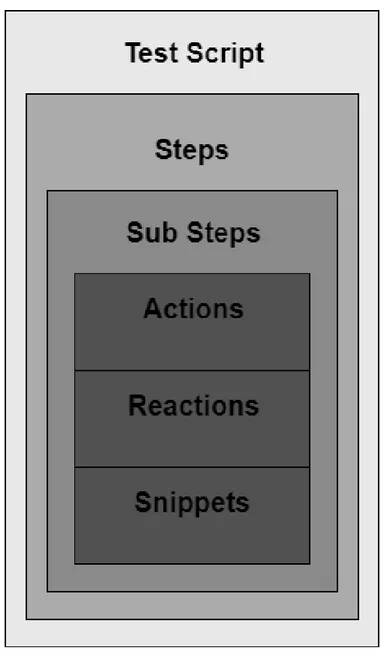
2.2 Test script structure . . . 6
2.3 Payload frequencies by categories . . . 9
2.4 Percentage of relevant changes . . . 10
2.5 Precenteg of relevant changes among signals . . . 11
2.6 DigitalSignal Changes . . . 15
2.7 AnalogSignal Changes . . . 15
2.8 CustomSignal changes . . . 16
3.1 Identified Test Levels . . . 18
3.2 Vehicle Breakdown to the System Level . . . 19
4.1 General architecture of the Test Environment . . . 26
4.2 DCUTerm . . . 28
4.3 Tracked signals . . . 28
4.4 Potential Final Architecture of The Proposed Solution . . . 30
4.5 Architecture of The Proposed Solution . . . 31
List of Tables
2.1 Payload type names and frequencies . . . 8
2.2 Payload frequencies by categories . . . 8
2.3 Number of lines changed by category and operation . . . 10
2.4 Number of lines changes by category (with and without irrelevant operation) 11 2.5 Number of signal changes by category (with and without irrelevant opera-tions) . . . 12
2.6 Number of control changes by category (with and without irrelevant oper-ations . . . 12
3.1 TCMS Chekpoints Model . . . 20
3.2 Test Documentation Overview . . . 21
Chapter 1
Introduction
Today, the software is an essential part of our life, it is everywhere. Our businesses, everyday activities, even our lives depend on the quality performance of some software. Malfunctioning of some part of the software can give us a big headache, or even put our lives in danger. Because of that, it is important to make sure that software is reliable. Software testing is widely consider to be one of the most important parts of software development life-cycle. It represents actions that are needed to be performed in order to confirm that software is firm, reliable, and that is behaving according to its requirements. Software testing is never ending process, there is never enough time or resources for testing. Even when it is finished by software testers, you can not be sure that software is bug-free. After its release, users can be seen as testers. Unfortunately in the context of safety critical systems sometimes that can be catastrophic. The latest example of that is an accident that occurred on Boeing 737 [1]. Because of the costs and time that is needed for software testing, in the industry, a lot of companies are trying to implement automation testing in their development process. Automation testing comes with its advantages and disadvantages. Studies showed that biggest advantages of automation in software testing are re-usability of test cases and reduced amount of time that is needed for test execution, but drawbacks are costs that are needed for buying a tool, training the employees and designing test cases [2].
This thesis is divided into the five chapters. The Chapter 1 gives a brief description of a problem that we are addressing, and how we planned to conduct our research. Data Analysis that was needed in order to investigate most common changes in test script is described in Chapter 2. Further analysis of testing processes and life cycle of automated test scripts is discussed in Chapter 3. We proposed a new testing tool in Chapter 4. Our conclusions are drawn in the final Chapter 5.
1.1
Background information and problem formulation
Bombardier Transportation has developed internally a platform for testing train’s software referred to as a Virtual Train environment. This platform supports automated execution of test scripts, and for creating those scripts they are using tools that are developed in Bombardier Transportation. In order to improve their testing process, Bombardier is interested in writing test scripts as close as possible to the natural language. With this thesis we seek to address challenges that are preventing longer life-cycle and re-usability of test scripts.
Introduction
to identify the possible improvements to the testing process by evaluating approaches of designing and creating executable test scripts. Conventionally, before writing or modifying a test script several phases have to be run. Usually, the mentioned phases includes the following: requirement specification, test specification and the test case itself. Every phase needs to be reviewed and validated in a processes which involves management of internal resources but also third parties such as quality control inspectors. The process is followed by a lot of bureaucracy and is really time and resource consuming. All the changes to the system usually lead to some, or all, of the phases to be run again leading to more time and resources being spent. This is posing a special problem for the environments in which the changes are rather frequent.
Re-usability of test cases is also an interesting problem that we want to investigate. There are several projects in Bombardier Transportation with a similar requirements where test cases can be re-used. With re-usable test cases, the process of software testing might become more affordable.
This thesis aims to provide answers to the following research questions:
∙ RQ1 - What are the common events triggering changes to automated test script? ∙ RQ2 - In what way does the testing life-cycle affect development of automated test
scripts?
∙ RQ3 - How can a natural language based tool, for test script creation, affect the testing processes from the maintainability, readability and re-usability aspects?
1.2
Related work
In order to better understand what problem we are facing, we investigated articles from two scientific databases IEEE Xplore and ACM Digital Library. The focus was on several subjects that are related to our topic. Those are testing of safety-critical systems, re-usability of test cases or test scripts, and their maintenance. The time span in which the papers were explored stretches from 1994 up to present.
In the context of safety-critical systems, our focus was on train system testing and on avionic system testing, topics extensively investigated in research ([3, 4, 5, 6]). They are focused on researching different tools, natural language semantics, and other test automation strategies that could improve the testing of safety-critical systems. In the context of our problem, these findings are relevant and useful for our research.
In the train system testing context, Zhang et al. [3] proposes a tool for generating test sequences for CTCS-3 Train Control System from MS Word formatted test cases, the tool, at the time of publishing the paper, was not fully able to generate test scripts without additional user inputs and, as authors described, was used as more powerful editing tool for test sequences. The difference in contribution when it comes to our research is that we created a proof of concept tool for writing test cases or test specifications.
The second paper in the same context, by Venticinqueet et al. [4], investigated how the natural language semantics can be used to map and trace test scripts to a requirement.
Introduction
library where they in the end claim that such an approach reduces the need of modifying and recompiling of the software. In our case, we investigated how a similar approach can reduce the need of modifying of test scripts in the context of Bombardier Transportation and what are the most common reasons for modifying them in the same context.
When it comes to the context of testing avionic systems the paper by A. K. Jha [6] extensively researches the test automation in it and puts some focus on the Data-Driven Test Strategy in which scripts structures remain the same and only inputs and outputs are modified by the need. In their context, they prove that this approach is having a significant effect on reducing the effort of developing test scripts. This is one of the aspects that our tool is based on.
In the context of the re-usability of test cases or test scripts, this is extensively invasti-gated in research ([7, 8, 9]). Research is focused on different approaches of identifying reusable test cases. The conclusions of these papers are of interest in our research. Dhareula et al. [7] are investigating identifications of the attributes of test cases for re-usability in the context of regression testing. They categorized the regression test selection techniques proposed in two groups: code-based techniques and requirement based tech-niques. When it comes to our research where we are investigating re-usability of test cases, and what is affecting those changes.
In the Black Box testing context, Vignjevic et al. [8] proposed a tool as a solution for the high re-usability of test suites. They claim that the proposed tool saves time for an adaptation of reused test suites between projects. Their tool is designed as a group of software tools that should complete the testing cycle of the project, from gathering the requirements, test execution, and generation of the report. Our tool is intended to merge, or at least to reduce the differences between writing requirements, test cases, and test scripts. Test Case Re-usability Metrics Models (TCRMM) is introduced by Juan et al. [9]. It is measuring re-usability of test cases and with that, it is possible to identify the most effective reuse strategies. According to [9] there are four re-usability factors understandability, changeability, independence, and universal. These factors will help in developing the re-usability assessment model. When it comes to our research, identified re-usability factors were useful during identification of reusable test cases.
1.3
Method
In order to successfully perform this research, we conducted a case study in Bombardier Transportation, the following steps that are suggested by Wohlin et al. [10]. The goal of the study was to help us understand the testing process in Bombardier Transportation, give us more information about test script life-cycle, find opportunities for re-usable test cases, as well as investigate the linguistic semantic used in the test specification and test case documents. Data for this case study has been provided to us, and previous versions of Bombardier Transportation’s test scripts are saved in their Version Control System, system requirement, test specification, and test case document. We have analyzed this data, and more details about this are written in Section 2, and introduce ourselves with a detailed grasp of the process used in Bombardier Transportation. Further analysis gave us answers on how changes in the test script have affected the testing process and why were they changed in the first place. Also, we investigated parts of the test script that haven’t been changed. They gave us insight about re-usability opportunities in test scripts. And finally, the specific semantic used in the test specification and test case documents is going to be noted as it is important for the natural language tool to be based precisely on it.
Introduction
Further steps include creating a proof of concept natural language based tool with the previous findings in mind. The tool demos were presented to Bombardier Transportation’s engineers involved in the testing life cycle. This way we want to extract the data if the semantic structure of the proposed tool is similar enough to formal documents produced in different phases of the test script development life cycle so that it can replace them to the extent.
Chapter 2
Data Analysis
2.1
Background information
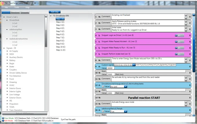
The test scripts that were analyzed for this research were written during the development for the C30 project. The C30 project represent one of the trains developed by Bom-bardier Transportation. These test scripts were created using the TAF (Test automation framework) tool. The framework consists out of two tools. The first tool is used for cre-ating and editing scripts, Test script editor (TSE). The TSE offers test engineer various benefits when it comes to creating automated test scripts that simulate different signals inside the train. It is user-friendly application with a proper GUI that allows the user simple drag and drop scripting.The tool and one of those scripts are presented in Picture 2.1. The second tool, Test Execution Manager (TEM), is used for handling and executing
Figure 2.1: Test script editor
Data Analysis
script analysis. Structure of these scripts is straightforward. After tags, that are used for initialization of the scripts, its script’s version and its name, tool’s version, the script is constructed from one or more Step tags. Later on, each step contains the different number of SubStep tags, that can be categorized into actions, reactions, and snippets. Operations that are performed on System Under Test (SUT) are represented with actions and reactions are used to verify the SUT response. The Snippets are used to merge one or more sub-steps inside the sub-step. It is useful for creating and defining instructions that are frequently used. The tags that are of interest for our research are Payload tag. They can be of a different type, and they are used for defining the information that is going to be sent so the script could be executed successfully. The structure of the test script is presented in figure below.
Data Analysis
2.2
Initial Analysis
As already mentioned before the needed data for the thesis kick-off was provided by Bombardier Transportation in the form of Visual SourceSafe (VSS)[11] virtual library containing XML formatted testing scripts. An initial analysis of the test script structure was performed to gain insight into what script parts are relevant. The conclusion made by this analysis was that the blocks with the tag name "Payload" carry the most rele-vant information when it comes to our research. Example of one of these "Payloads" is presented bellow.
Listing 2.1: Example of payload 1 <Payload x s i : t y p e=" A n a l o g S i g n a l ">
2 <D e s c r i p t i o n>A2_EKEY2:Badge i s p r e s e n t and v a l i d i n d e s k s t a t i o n (
BOOL)</ D e s c r i p t i o n>
3 <F u l l P a t h>S i g n a l s . E l e c t r i c a l Key . IP . A2_EKEY2:Badge i s p r e s e n t and
v a l i d i n d e s k s t a t i o n (BOOL)</ F u l l P a t h> 4 <VCSPath>3 5 . IP PD I n p u t s . 1 . 0</VCSPath> 5 <BusType>IP</BusType> 6 <MWTSignalName /> 7 <ReactionTimeOutInMS>6000</ ReactionTimeOutInMS> 8 <S e t S i g n a l>t r u e</ S e t S i g n a l> 9 <L o c k S i g n a l>t r u e</ L o c k S i g n a l> 10 <MeasureDurationInMS>0</ MeasureDurationInMS> 11 <MWTVersion>0</MWTVersion> 12 <VCSVersion>1</ VCSVersion> 13 <VCSID>20303</VCSID> 14 <R e q u i r e F l a n k O n R e a c t i o n> f a l s e</ R e q u i r e F l a n k O n R e a c t i o n> 15 <ToleranceInMS>0</ ToleranceInMS> 16 <WaitInMS>0</WaitInMS> 17 <BusID>3</BusID> 18 <BusName>c s t 1</BusName> 19 <BusAddress>3 7 0 0 0 1 01 : 1 0 . 0 . 7 . 4 1</ BusAddress> 20 <B u s A d d r e s s O f f s e t>6</ B u s A d d r e s s O f f s e t> 21 <DataType>BOOLEAN8</ DataType> 22 <DCUIPSignalName> A2_EKEY2_Badge_is_present_and_valid_in_desk_station_ (BOOL)</ DCUIPSignalName> 23 <S i g n a l A d d r e s s>6</ S i g n a l A d d r e s s> 24 <S i g n a l T y p e>R e a c t i o n</ S i g n a l T y p e> 25 <UnitTypeName>IP</UnitTypeName> 26 <S i g n a l D i r e c t i o n>I n</ S i g n a l D i r e c t i o n> 27 <UnitID>161</ UnitID>
28 <IsHex> f a l s e</ IsHex>
29 <Ad dr es sin gS che me>ByteInTelegram</ A ddr es si ngS che me> 30 <MinValue> −2147483648</ MinValue> 31 <MaxValue>2 1 4 7 4 8 3 6 4 7</MaxValue> 32 <C u r r e n t V a l u e>1</ C u r r e n t V a l u e> 33 <BetweenValue>0</ BetweenValue> 34 <C u r r e n t R e a c t i o n O p e r a t o r>Equal</ C u r r e n t R e a c t i o n O p e r a t o r> 35 <S i gn a l Da t aT y pe>I n t</ Si g na l Da t aT y p e> 36 </ Payload>
As it can be seen above these "Payloads" can contain various information with various formats and thus they can be of different types. Having this in mind we conducted a second analysis aiming to gain information on what these types are and their frequencies. The analysis was run on 56 different script files, each of them being the final version.
Data Analysis
Payload Type
Count
%
% w/o Comments
Snippet
163
3,159
3,816
Comment
889
17,229
0,000
AnalogSignal
122
2,364
2,856
CustomSignal
928
17,984
21,728
DigitalSignal
1138
22,054
26,645
SelectionControl
551
10,678
12,901
WaitControl
594
11,512
13,908
ParallelReactionStart
65
1,260
1,522
ParallelSubReactionInit
65
1,260
1,522
ParallelSubReactionStart
65
1,260
1,522
ParallelSubReactionEnd
65
1,260
1,522
ParallelReactionEnd
65
1,260
1,522
AnalogControl
181
3,508
4,238
SemiControl
18
0,349
0,421
ReInitiateSimulations
2
0,039
0,047
SelectionIndicator
188
3,643
4,402
AnalogIndicator
38
0,736
0,890
Unit
23
0,446
0,539
5160
100
100
Table 2.1: Payload type names and frequencies
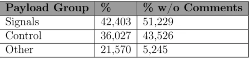
As it can be read in Table 2.1, the results of the analysis identified 18 different Payload types. These Payload types can be further grouped in 3 different categories, in Signals, Controls, and Other. In Table 2.1 the Signals are marked by the green color and the Controls by the blue. Important information is also that the Comment Payloads are making more than 17% of scripts, as they aren’t relevant for scripts functioning the statistics were performed with them excluded. Having in mind previous conclusions the results were summed up by the defined categories as well.
Payload Group % % w/o Comments
Signals 42,403 51,229
Control 36,027 43,526
Other 21,570 5,245
Data Analysis
Figure 2.3: Payload frequencies by categories
2.3
Steps and SubSteps analysis
XML scripts that were provided to us consist of the series of Steps and SubSteps. In those tags, further action is called and tested. We wanted to investigate if there is a trend in changes in the number of Steps or SubSteps in test script versions, or those changes are random. This was done using a script that counts Steps and Substeps of each test script version and calculates their average value for a test script. After analysis of gained results, the conclusion was made that changes in the frequency of both Steps and SubSteps are random.
2.4
Initial changes analysis
The next step is to extract and analyse the precise changes made in scripts between each of its versions sequentially. For this, all the scripts and their versions were extracted and sorted resulting in a pool of approx. 250 MB of data. The plan was to find the most appropriate format of the data for the difference analysis, without losing the relevant information in the process and using such formatted data to extract relevant changes and information about them. Having this in mind it was first decided to change the names of Payload types to their corresponding category name. The "Other" category wasn’t taken into consideration here as it only makes approx. 5% of all Payloads with comments excluded. The script was created for modifying the names and it was run on the sorted data pool creating a new pool with the renamed tags. At this point, data was prepared for comparing. Another Python script was created for extracting the differences between test script versions. The Python script used a xmldiff[12], an open source library
Data Analysis
for the purposes of extracting the differences from XML files. The test script versions were compared sequentially and it was decided that initial versions should not be taken in consideration as they carried only the data of the test script initialization, thus the comparison between the initial version and next version would carry a considerable amount of changes and it would distort the results in further analysis. The result of running this Python script was files with all the changes in the form of a list of actions containing information that should be done to transform the first XML file into the second one. Further, an additional Python script was created to analyse the amount and type of changes throughout all test scripts, the result is shown in tables 2.3 and 2.4.
move insert update-text rename delete insert-attribute
Signal 197455 57533 58086 121220 13928 1927
Control 73597 12621 10932 38890 3362 1387
All 271052 70154 69018 160110 17290 3314
Table 2.3: Number of lines changed by category and operation
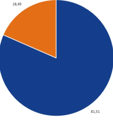
Figure 2.4: Percentage of relevant changes
Data Analysis
SUM Relevant
SUM ALL
% Relevant changes
% ALL
Signal
131851
450149
81,507
76,175
Control
29915
140789
18,492
23,825
All
161766
590938
100
100
Table 2.4: Number of lines changes by category (with and without irrelevant operation)
Figure 2.5: Precenteg of relevant changes among signals
When these numbers are summed up and the percentage is calculated by categories like shown in Table 2.4 it can be noticed that from all the changed line ones that are affecting the Signals contribute to approx. 81% ( 76% with irrelevant operations included) of all changes between these two categories. With this, we can already draw a conclusion that Signals are in fact parts of automated test scripts that are changed the most, and thus confirming our initial prediction in the Section 2.2.
2.5
Changes analysis by category
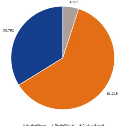
After initial data analysis that was explained in 2.2 further analysis by category was conducted. The goal of this analysis was to investigate which category in signals and controls was changed the most. This was done by updating the script that was used for the initial differences analysis script. Based on the result from this analysis it was concluded that among Signals, DigitalSignal was changed the most (65%), changes in CustomSignal were the second (30%), AnalogSignal was changed least times (0.03%), and among Controls, it was SelectionControl (60%). These results are presented on tables 2.5 and 2.6. Figure 2.5 shows graphical representation of the percentage of changes among
Data Analysis
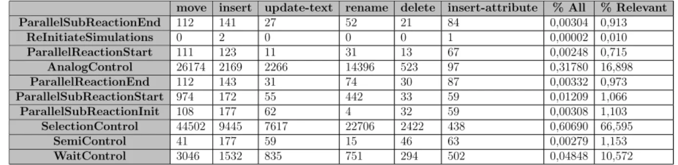
signals. Based on the number of percentages of each category in Signals, the results of changes are as expected. But for the Controls number of changes in one category is of interest, that is AnalogControl. Despite WaitControl is the second most frequent category in Controls, the number of its changes is 0,04848, and the number of the third most frequent one, AnalogControl is 0,31780.
move insert update-text rename delete insert-attribute % ALL % Relevant
AnalogSignal 7385 2798 3011 3928 688 86 3,86 4,993
DigitalSignal 141900 34521 37186 81899 7862 1144 65,68 61,215
CustomSignal 63506 20214 17889 33153 5755 697 30,46 33,792
Table 2.5: Number of signal changes by category (with and without irrelevant operations)
move insert update-text rename delete insert-attribute % All % Relevant ParallelSubReactionEnd 112 141 27 52 21 84 0,00304 0,913 ReInitiateSimulations 0 2 0 0 0 1 0,00002 0,010 ParallelReactionStart 111 123 11 31 13 67 0,00248 0,715 AnalogControl 26174 2169 2266 14396 523 97 0,31780 16,898 ParallelReactionEnd 112 143 31 74 30 87 0,00332 0,973 ParallelSubReactionStart 974 172 55 442 33 59 0,01209 1,066 ParallelSubReactionInit 108 177 62 4 32 59 0,00308 1,103 SelectionControl 44502 9445 7617 22706 2422 438 0,60690 66,595 SemiControl 41 177 59 15 46 63 0,00279 1,153 WaitControl 3046 1532 835 751 294 502 0,04848 10,572
Table 2.6: Number of control changes by category (with and without irrelevant operations
2.6
Changes analysis inside signals
After initial changes analysis, and changes analysis by category next step was to analyse changes inside the signals. The goal of this analysis was to find out which tags inside Signal was affected with most changes. The first step of this analysis was to investigate the structure of all three types of signals. The conclusions of this investigation were that all three types of signals are constructed with different types of tags. Most of the tags from DigitalSignal and AnalogSignal are the same, with some additional tags that are used in AnalogSignal. CustomSignal has its own child that DigitalSignal and AnalogSignal does not have, it is called CCUUnit and it has its additional tags. Structure of each of these signals is presented bellow.
Listing 2.2: Digital signal 1 <Payload x s i : t y p e=" D i g i t a l S i g n a l ">
2 <D e s c r i p t i o n>A 1 : A c t i v a t e t r a i n i n d i c a t i o n</ D e s c r i p t i o n>
3 <F u l l P a t h>S i g n a l s . T r a i n O p e r a t i o n .MIODX. A 1 : A c t i v a t e t r a i n i n d i c a t i o n
</ F u l l P a t h>
4 <VCSPath>6 0 .MIODX Outputs . 2 7 . 0</VCSPath> 5 <BusType>MIODX</BusType>
6 <MWTSignalName />
Data Analysis 14 <R e q u i r e F l a n k O n R e a c t i o n>t r u e</ R e q u i r e F l a n k O n R e a c t i o n> 15 <ToleranceInMS>0</ ToleranceInMS> 16 <WaitInMS>0</WaitInMS> 17 <BusID>2</BusID> 18 <BusName>MvbMVB2</BusName> 19 <BusAddress>A28</ BusAddress> 20 <B u s A d d r e s s O f f s e t>10</ B u s A d d r e s s O f f s e t> 21 <DataType>B o o l e a n</ DataType> 22 <DCUIPSignalName>A 1 _ A c t i v a t e _ t r a i n _ i n d i c a t i o n</DCUIPSignalName> 23 <S i g n a l A d d r e s s>1</ S i g n a l A d d r e s s> 24 <S i g n a l T y p e>R e a c t i o n</ S i g n a l T y p e> 25 <UnitTypeName>MIODX</UnitTypeName> 26 <S i g n a l D i r e c t i o n>Out</ S i g n a l D i r e c t i o n> 27 <UnitID>34</ UnitID>
28 <IsHex>t r u e</ IsHex>
29 <Ad dr es sin gS che me>BitInWordInTelegram</ Ad dr ess in gSc he me> 30 <C u r r e n t V a l u e> f a l s e</ C u r r e n t V a l u e>
31</ Payload>
Listing 2.3: Analog Signal 1 <Payload x s i : t y p e=" A n a l o g S i g n a l ">
2 <D e s c r i p t i o n>A1:A1: Wheel r o t a t i o n a l speed , a x l e 1</ D e s c r i p t i o n> 3 <F u l l P a t h>S i g n a l s . Brake .MVB. A1:A1: Wheel r o t a t i o n a l speed , a x l e 1</
F u l l P a t h>
4 <VCSPath>7 .MVB Analog I n p u t s . 0 . 2 2</VCSPath> 5 <BusType>MVB</BusType> 6 <MWTSignalName /> 7 <ReactionTimeOutInMS>10000</ ReactionTimeOutInMS> 8 <S e t S i g n a l>t r u e</ S e t S i g n a l> 9 <L o c k S i g n a l>t r u e</ L o c k S i g n a l> 10 <MeasureDurationInMS>0</ MeasureDurationInMS> 11 <MWTVersion>0</MWTVersion> 12 <VCSVersion>2</ VCSVersion> 13 <VCSID>2626</VCSID> 14 <R e q u i r e F l a n k O n R e a c t i o n>t r u e</ R e q u i r e F l a n k O n R e a c t i o n> 15 <ToleranceInMS>0</ ToleranceInMS> 16 <WaitInMS>0</WaitInMS> 17 <BusID>0</BusID> 18 <BusName>MvbMVB1</BusName> 19 <BusAddress>710</ BusAddress> 20 <B u s A d d r e s s O f f s e t>128</ B u s A d d r e s s O f f s e t> 21 <DataType>U16</ DataType> 22 <DCUIPSignalName>A1_A1__Wheel_rotational_speed__axle_1</ DCUIPSignalName> 23 <S i g n a l A d d r e s s>128</ S i g n a l A d d r e s s> 24 <S i g n a l T y p e>R e a c t i o n</ S i g n a l T y p e> 25 <UnitTypeName>MVB</UnitTypeName> 26 <S i g n a l D i r e c t i o n>I n</ S i g n a l D i r e c t i o n> 27 <UnitID>86</ UnitID>
28 <IsHex>t r u e</ IsHex>
29 <Ad dr es sin gS che me>BitInWordInTelegram</ Ad dr ess in gSc he me> 30 <MinValue>−32768</ MinValue> 31 <MaxValue>32767</MaxValue> 32 <C u r r e n t V a l u e>0</ C u r r e n t V a l u e> 33 <BetweenValue>0</ BetweenValue> 34 <C u r r e n t R e a c t i o n O p e r a t o r>Equal</ C u r r e n t R e a c t i o n O p e r a t o r> 35 <S i gn a l Da t aT y pe>I n t</ Si g na l Da t aT y p e>
Data Analysis
36</ Payload>
Listing 2.4: Custom signal 1 <Payload x s i : t y p e=" CustomSignal "> 2 <C C U U n i t C o l l e c t i o n> 3 <Name>CCU−O A1</Name> 4 <CCUUnits> 5 <CCUUnit> 6 <Name>CCU−O A2</Name> 7 <IPAddress> 1 0 . 0 . 1 . 4 1</ IPAddress> 8 <Port>54321</ Port> 9 <IsValidSignalMWTName>MWT. TC_B_TC_B_Supervision_T3 . TC_BV_S_Leader</ IsValidSignalMWTName> 10 <U s e V a l i d S i g n a l>t r u e</ U s e V a l i d S i g n a l> 11 <LogTaskLevel>T2</ LogTaskLevel> 12 <V e r s i o n>1</ V e r s i o n> 13 </CCUUnit> 14 <CCUUnit> 15 <Name>CCU−O A1</Name> 16 <IPAddress> 1 0 . 0 . 1 . 1 1</ IPAddress> 17 <Port>54321</ Port> 18 <IsValidSignalMWTName>MWT. TC_B_TC_B_Supervision_T3 . TC_BV_S_Leader</ IsValidSignalMWTName> 19 <U s e V a l i d S i g n a l>t r u e</ U s e V a l i d S i g n a l> 20 <LogTaskLevel>T2</ LogTaskLevel> 21 <V e r s i o n>1</ V e r s i o n> 22 </CCUUnit> 23 </CCUUnits> 24 </ C C U U n i t C o l l e c t i o n>
25 <MWTSignalName>MWT. TC_BI_iCCUS_AToCCUO . TC_BI_CCUS_X_LifeSignA</
MWTSignalName> 26 <ReactionTimeOutInMS>180000</ ReactionTimeOutInMS> 27 <C u r r e n t V a l u e>1</ C u r r e n t V a l u e> 28 <BetweenValue>0</ BetweenValue> 29 <C u r r e n t R e a c t i o n O p e r a t o r>GreaterEqualThan</ C u r r e n t R e a c t i o n O p e r a t o r> 30 <MeasureDurationInMS>0</ MeasureDurationInMS> 31 <M a r k S i g n a l> f a l s e</ M a r k S i g n a l> 32 <R e q u i r e F l a n k O n R e a c t i o n> f a l s e</ R e q u i r e F l a n k O n R e a c t i o n> 33 <ToleranceInMS>0</ ToleranceInMS> 34 <WaitInMS>0</WaitInMS> 35</ Payload>
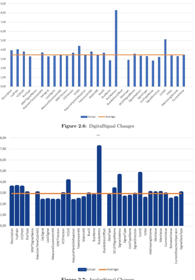
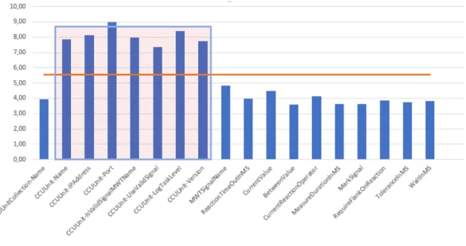
In both DigitaLSignal and AnalogSignal tag that is called BusAddress was changed the most. Changes in all other tags were fairly close to the average, while BusAddress was changed 2.4 times more than average. Changes for DigitalSignal and AnalogSingal are presented on Figure 2.6 and Figure 2.7. On these figures "Actual" represents percentage of changes inside signals. In CustomSignal most changes affected tags that are related to CCUUnit. On average CCUUnit and related tags changed 1.45 times more than the rest of them.Changes for CustomSignal are presented on Figure 2.8.
Data Analysis
Figure 2.6: DigitalSignal Changes
Data Analysis
Figure 2.8: CustomSignal changes
2.7
Data analysis conclusion
Before the analysis began on automated test scripts of C30 project, an assumption was made that the Signals would be the parts of the scripts changed the most. This assump-tion was based on the fact that the whole train system funcassump-tions through signal exchanges, and thus they are the most susceptible to changes triggering the chain change reaction to automated test scripts. This was confirmed on few levels. The first indication for this assumption to be true was the fact that Signal Payloads made around 51% of all of the Payloads in analyzed test scripts. The first confirmation came from the fact that out of two major Payload groups, Signal and Control, Signals had more then 81% of relevant line changes in all of the analyzed test scripts. Further analysis showed that in the var-ious Signal Payloads most of the changes made were on the specific data correlating to implementation of the train. In DigitalSignal and AnalogSignal Payloads information of a BusAddress changed 2.4 times more than average compared to the rest of information Tags, while in CustomSignal CCUnit and it’s information was changed 1.45 times more than average. These findings exposed an opportunity for potential improvement of au-tomated test scripts maintenance. At this point, the idea for improvement was seen in implementing a better system for handling Signal changes.
Chapter 3
Development Life Cycle of Automated
Test Scripts
To understand better the whole Development Life Cycle Automated Test Scripts it is mandatory to at least understand the basic procedures and strategies used for Verification and Validation in context of Bombardier Transportation. For this purposes we have taken few steps, the first one was to read and analyze the official documentation describing these processes and strategies. The second step was to interview the engineers directly involved in the process with the aim to gain more insight with the assumption that formal documents and things documented within them usually deviate in a way from the real world cases.
3.1
TCMS Verification and Validation
As the whole research and analysis revolved around TCMS scripts and System testing logical step was to further stay in the same scope, following that logic the document of interest was the official procedure document for TCMS Verification and Validation. This document was created for the purposes of describing overall Verification and Validation strategies in order to comply to the EN 50657 [13] and EN 50128 [14] standards. Although this document was created for the purposes of TCMS it is defining overall V&V strategies and should be used in other projects with specific refinements.
3.1.1
Testing Levels ans Scopes
Within their V&V process Bombardier Transportation uses two different verification tech-niques:
∙ Review ∙ Testing
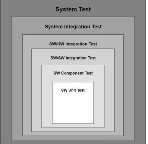
In this case testing, as in process of executing test cases on software and/or hardware, is the point of interest. There are in general six levels of the TCMS architecture and the requirements and because of that there are six test levels identified in the figure 3.1.
Development Life Cycle of Automated Test Scripts
Figure 3.1: Identified Test Levels
From this it can be concluded that the System is highly complex and consists of multiple parts and all of the parts have to be checked and made sure they function properly. Regardless of this how many levels there is the top priority is to reach the System Testing as soon as possible because these tests validate main System functionalities and are only the first, and the lowest, level functionalities of the whole system in which trains are gonna be functioning. To have a better understanding just how important is to reach System level Testing figure 3.2 represents the breakdown of the System in which TCMS has to function flawlessly.
Development Life Cycle of Automated Test Scripts
Figure 3.2: Vehicle Breakdown to the System Level
The whole product consists of various parts and has to function in yet another higher system environment and for all of this to function properly extensive testing has to be done on all of these levels. This is why the System level Testing poses as a one of the top priorities, it has to be reached as soon as possible as it influences the processes on the higher abstraction levels on a great scale.
3.1.2
Phases and Documentation
From the previously mentioned facts it can already be concluded that not only the whole testing process has many layers but that due it’s complexity strict rules need to be fol-lowed in order to organize and track the whole V&V process. According to the TCMS Verification and Validation document in regards of Testing a batch of documents has to be created in various checkpoints. Most of these documents have a life cycles of their own and they usually consist out of three:
∙ Preparation and creation of the document ∙ Document review
Development Life Cycle of Automated Test Scripts
Checkpoint code Checkpoint title
T0 TCMS Project Start
T1 TCMS Subsystem Requirements Freeze
T2 TCMS Subsystem Architecture Freeze
T3 TCMS Application SW Requirements Freeze
T4 TCMS Ready for Integration and Testing
T5 TCMS Ready for Vehicle Integration
T6 TCMS Ready for Final Validation
T7 TCMS Ready for Assessment
T8 TCMS Ready for Vehicle Homologation
T9 TCMS Project Closure
Table 3.1: TCMS Chekpoints Model
In this case Document review is considered as an internal review and it is mandatory to be conducted on every document as part of documentation is generated by specialized tools or are simple reports. For every document there is are defined times when they should be started and delivered. These times are defined as checkpoints in an internal model called TCMS Checkpoint Model. This model, checkpoints codes, and checkpoints titles are presented on Table 3.1. These checkpoints represent the phases of the TCMS Development Life Cycle and according to TCMS Checkpoint Model Instructions Document they are agreed for governing every new project and generalizingly market with Tx. The documents overview can be seen in the Table 3.2.
For the purposes of System Testing, the point of interest for this research, all of the TCMS test are based on TCMS System requirements and the test cases are documented in TCMS System Test Specification document. These test are usually ran using different tools and environments, mostly simulated ones. Because of the simulated environments always deviate in a way from the real world ones the differences are always calculated, documented and taken in consideration. Only regression test have to be ran on the real world environment. All of the test results are documented in the System Test Report document with all the relevant details. In the end, the formal review and test reports are submitted for TCMS Verification, Validation ans Assessment.
Dev elopmen t Life Cycle of Automated T est Scripts
Document Description Internal reveiw required Starting checkpoint Ending checkpoint Test Plan The document contains general requirements and is a part of Test Execution Plan. Yes Not specified T1
Test Execution Plan The doucment contains specific requirements for related test levels. Yes T3 - SW Component T4 - System level
T4 - SW Component T5 - System level Classification Tree The document is a part of Test Specification and is used to indentify all of the test cases that are meeting the requirements. Yes T3 - SW Component
T4 - System level
T4 - SW Component T5 - System level Test Specification The document describes the test design. Yes T3 - SW Component
T4 - System level
T4 - SW Component T5 - System level Test Script Test Scripts contain instructions for automatical execution of test cases or test sequences. Yes T3 - SW Component
T4 - System level
T4 - SW Component T5 - System level Test Traceability Matrix An automatically generated document linking the other relevant documents and artifacts to each other. Yes T3 - SW Component
T4 - System level
T4 - SW Component T5 - System level Test Record The document contains the results of the test cases, it may be created either manually or automatically. No Not specified T4 - SW Component
T5 - System level Test Iteration Report The document contains the results of the thest cases defined in the Test Execution Plan for the assigned test specification. It is an intermediate report. No Not specified T4 - SW Component
T5 - System level Test Report The document contains the same things as a Test Iteration Report but it is a final report and it will be used for validation. No Not specified T4 - SW Component
T5 - System level Test Metrics Various documented data about previously done testing collected for the purposes of better understanding, comparing and improving various approaches. No Not specified T7
Table 3.2: Test Documentation Overview
Development Life Cycle of Automated Test Scripts
Step Test case Reaction
Initial State:
Train is in Energy save mode
1
Press the
‘Till’ flashing button on the side pillars
Place valid card in key holder on drivers desk in A1 From IDU, enter correct authorization code and activate cab.
Check that:
- Main menu is shown on IDU
- Battery contactors in A1 and A2 are Closed under “Kraft-försörjning” - ACM state is “In Operation” under “Kraft-försörjning”
- an event is set indicating that cab A1 has been activated 2 Wait until Main Reservoir Pressure is 1001kPa On IDU check that:
- Main compressor status for B1 and B2 under Tryckluft is shown “OFF” 3 Press “Körklar” on drivers desk
Check that:
- Holding brakes are applied - All the MCMs are in state “Charged” 4
Deactive the cab A1
Activate the cab A2 with valid authorized user Repeat the steps 1-3 from Cab A2
Table 3.3: Test case example
3.1.3
Test specification
Test specification represents a document that contains list of test cases that should be executed. Each test case contains set of steps that are needed to be done in order to execute test case properly. Also, for each step there is a reaction that should occur. This document is used by test engineers for performing manual testing. One test case from the document is presented on the Table 3.3.
3.2
Interview
In order to gain better insight about testing processes in Bombardier Transportation, an interview B.1 was conducted. The interview took place inside Bombardier Transportation and respondent was Markus Einarson. He has been working in Bombardier Transportation in the area of testing the TCMS software and was a logical choice for this interview, because of his involvement in companies testing process and he is the responsible person for previously analyzed TAF test scripts. The goals for this interview were to find out:
∙ What are the factors that are affecting testing process?
∙ What are advantages and disadvantages of TAF test tool used in C30 project? ∙ How are changes inside the project affecting testing process, and what is causing
them?
∙ Are there any potential opportunities for better re-usability of automated test scripts and/or their parts ?
∙ Are there any semantic standards that could be used in keyword based writing of the test scripts?
Development Life Cycle of Automated Test Scripts
affected a normal drive cycle of the train, in other words if the normal behaviour is affected by them. This kind of tests do not follow any complicated procedure for their creation, meaning that they aren’t based on any type of documentation and the only artifacts are the automated test script instead. On the other hand, two other types of regression testing are documented and their documentation is kept in Rational DOORS[15]. These two types are regular and safety test cases and they are required to be run manually first, based on created test cases, then converted to automated test scripts. These test cases are created based on the software requirements, also documented and stored in Rational DOORS[15].
After that questions regarding test tool were asked. The tool that was used is TAF tool, and it consists of three parts, TAF script editor, TAF execution manager, and TAF test engine. One of the big advantages by Markus is that TAF tool is closely integrated with manual testing environment VCS (Vehicle Control Simulator). Also, TAF is user-friendly, the tester does not need to write the code, instead it is possible to select certain components, such as signals, buttons to push, etc... The drawback is that there is not a good export format for the TAF tool, which makes readability of test scripts much harder. When it comes to re-usability feature, with TAF tool it is possible to perform certain action multiple times by creating snippets. These snippets represent reusable parts that can trigger a chain update of TAF scripts if updated themselves.
Next set of questions were about changes inside the project, and how are they affecting the testing process. According to our respondent most of the changes are triggered by SCRs (Software Change Request), direct request for the change. These changes can be two sides as they can trigger changes in both directions, from software under test to automated test scripts and vice versa. Also, in case some changes are done in test cases that are documented in Rational DOORS[15], it is quite simple and straightforward to change the test script. When it comes to automation test script, which is executed every night, in case some failure happens during the execution test script is updated. The time that is needed for changing the test script varies from minutes to several hours, even days. Most of the time is spent for investigation of what actually needs to be updated. Our respondent confirmed conclusions that were made in previous data analysis, most of the changes were done on signals and on small parameters such as timings and changing signal names. When it comes to signal changes the TAF environment has a built in support function when a signal VCS library is changed. This function enables the user to check if the script has any of the signals in it changed but it requires the person to open every script, check for the possible change with the provided function and then manually update the signal. At the end of this question section we expressed and explained the idea for a data driven design of test where signals would be given aliases and those aliases would further be used in automated test scripts instead of direct signal names from the VCS library. In respondent opinion this could potentially increase re-usability of the scripts between different projects while having in mind no trains are the same and there would still be a need for adapting the scripts for the specific project.
When it comes to the standardized semantics for writing test specifications there isn’t any at the company level. But it is possible to identify some similarities in the documentation, so there is some informal standard on the project level. Also, the respondent gave us positive feedback about our idea for the keyword-based testing tool, although he also stated the concern that it the success of such tool depends on willingness of the staff to use and adapt to it.
Development Life Cycle of Automated Test Scripts
3.3
Chapter conclusion
Through analyzing the official documentation for the procedures and strategies in relation to the TCMS Verification and Validation, and conducting an interview with Bombardier Transportation, few conclusions could be made. The first important fact was that the two techniques used in the V&V process, review and testing, tightly depend one on another. This is due to fact that most of the phases leading to the final testing result require extensive documentation. This documentation has to be internally reviewed and approved first before moving to a next phase. This further poses as a challenge as the process is time consuming on it’s own but also it has to be done for multiple levels. The thigh relation between these two techniques and the consequential time consuming problem they create was yet again confirmed through conducted interview, the respondent stated that, although it is preferable for the whole testing process to start as soon as possible, it is waited for the whole project to reach certain maturity before the test start being implemented. The reason for this, as stated by the respondent, was the pure amount of changes the whole project goes through the early stages which would further create a chain reaction of changes through all of the deliverable down to the automated test scripts.
The second major conclusion from the research conducted for the purposes of this chapter was that the problems created from the facts in the first conclusion created a deviation from the official procedures and strategies for TCMS V&V. This deviation is seen through concrete practices of testing where separate, undocumented, tests are made. These tests represent general regression tests based purely on experience of test engineers. They are system level tests, which further implied the importance of the whole process to reach system level testing as soon as possible as the whole product has to be tested further on higher functionality levels.
Further, the important information gained from the interview confirmed our results from the Chapter 2. From the experience of the respondent, the changes made the most to automated test scripts are mainly from the fact that implementation specific data, such as signals, change often. The whole process, in the context of TAF scripts, is semi-automated and, although straight forward, can consume a lot of time. It was also stated that the TAF tool lacks in the ability to export the created scripts in a readable format. The best way to read the scripts is through the Script Editor itself and, although it is simple to install it, it is not convenient to do in case a third party has to gain access to the scripts.
Unfortunately, we were unable to to conduct more interviews regarding TAF scripts as the respondent was the only one responsible for creating them within C30 project. The information from the interview could be highly personal. Due to this fact the results and conclusions extracted from the interview should be treated with considerable caution.
Chapter 4
Proof of Concept Tool
4.1
Testing Environment
The process of creating and executing test script in Bombardier Transportation is quite complex, and in order to successfully finish it, several tools are used. As it was mentioned in Chapter 3, a tool that was used for creating the test scripts, the Test Automation Framework (TAF). The TAF was developed inside Bombardier Transportation, using C# programming language, with the intention to speed-up and automatize testing process. It consists of three different tools, TAF test script editor (TSE), TAF execution manager (TEM), and TAF test engine (TE). The TSE provides a GUI editor that is used for writing test scripts, TE is an application that serves to execute test scripts created with the TSE against TCMS or SoftTCMS, and the TEM serves to create and execute sessions. A session contains a list where tests scripts are defined to be executed. Bombardier Transportation is dealing with safety-critical systems, and because of that when it comes to changes of signal’s values timing is crucial. There is a huge amount of mathematical analysis behind the TE for dealing with responses from the SUT. With this it is possible to analyse signal’s values in different situations during the execution of the test script. The TAF has access to VSS Database. This database stores information about Sessions, Test Scripts and Snippets.
The TEM receives a script from the TSE, and it converts it to simple String which contains a set of commands that need to be executed. These commands are executed in Vehicle Control Simulator tool (VCS). This tool is consist of two parts, VCS Database and VCS Application. In the VCS Database information about the VCS application is stored. The VCS Application simulates train surroundings and parts of the TCMS. The TCMS is also tested with the VCS by using manual testing techniques. The VCS has its own development cycle, and it is being updated during the whole project. The TAF tool and the VCS are closely integrated and they are sharing the same data.
In order to monitor the status and values of signals that are being sent, TAF is using tool that is called Data Communication User Terminal (DCUTerm). With the DCUTerm it is possible to send commands in order to set or retrieve a signal, track its value, etc.. In order to communicate with some other system DCUTerm can use TCP/IP connection. The SoftTCMS represents a simulated environment of the Train Control Management System (TCMS). Both of them represent a test object which is built on standard Ether-net technology that allows easy integration with other systems. The architecture of the Testing Environment is presented on Figure 4.1.
Proof of Concept Tool
Figure 4.1: General architecture of the Test Environment
4.2
Connections inside Testing Environment
Communication between the TAF and the VCS can be established in two ways. One way is a simple Internet Protocol connection. The TAF is connected to the VCS using its IP address and port number. It sends a String which contains a set of commands that shall be executed inside the VCS. These commands consist of commands type, the path to the object, and value that is going to be set. Command types can be to set a signal value, get a value of a signal, lock a signal, etc... Each signal that is being manipulated with performs specified functions. Their identifiers and description of their functions are kept in the VCS database. In the respond, VCS sends a String where each command that is
Proof of Concept Tool
these commands differ between target systems. Some of them are opening a variable (signal), forcing a new value, or starting to log a signal. All of them can be executed by typing them directly to the DCUTerm. Also, the DCUTerm provides and API that exposes functions to control it from the third party software, this way it can be used to as an middle man in the communication between the third party software and the SUT. For example, in order to establish a connection with the SoftTCMS, DCUTerm is triggered by command "ConnectWith". For this command to be executed sucessfully DCUTerm needs to receive type of the connection (TCP/IP), IP address of the machine that runs the SoftTCMS (it can also be Localhost), and port number that is used by SoftTCMS. In order execute some of the commands on SUT, the DCUTerm can be triggered with "ExecuteCommand" function. This function also needs a String that contains command that should be executed. In our case for changing the value of a signal that could be "O SingalName/SignalValue". For confirming the changes on the signals that are made sign dot (".") is used. A simple example of invoking the DCUTerm and connecting it to the VCS can be seen in the Listing 4.1.
Listing 4.1: Initial Analysis Python Script 1
2 import c t y p e s
3 from win32com . c l i e n t import D i s p a t c h 4 import t i m e
5 dcuTerm = D i s p a t c h ("DCUTerm . App") 6 t i m e . s l e e p ( 1 0 )
7 dcuTerm . ConnectWith ("TCP/ IP ", " L o c a l h o s t " , " 6001 ") 8 print(" C o n n e c t i n g . . . ")
9 t i m e . s l e e p ( 1 0 ) 10
11 dcuTerm . ExecuteCommand (" o PLACEHOLDER. Enable_ Dev / 1 / . ") 12 t i m e . s l e e p ( 1 0 )
An example of the DCUTerm and use of its commands is shown in Figure 4.2. The tracking of the signal’s values is presented in Figure 4.3
Proof of Concept Tool
Proof of Concept Tool
4.3
Concept and Ideas for Suggested Solution
After analysis of test scripts, test processes inside Bombardier Transportation, and their testing environment next step was to develop a proof of concept tool that would suggest a new approach in creating test scripts for Bombardier Transportation. With our solution we aimed to improve couple of aspects:
∙ The re-usability of created automated test scripts within, as well as between, projects ∙ The readability of automated test scripts
∙ The maintenance time
For the first aspect the idea for the solution was firstly based on the fact that the products being developed by Bombardier Transportation belong to same family of prod-ucts, which are trains. From this fact we know that prodprod-ucts, although never completely the same, will in the end have a fairly big number of functionalities the same. All of these functionalities are in the end tested in one way or another and the tests are designed and documented in the Test Specification documents. These documents describe the tests on the high level, describing what should be tested and in what sequence leaving out the technical details. From the interview conducted for the purposes of Chapter 3 we know that Test Specification documents usually have the same or similar semantic between the projects, and within the projects the nomenclature is almost always informally standard-ized. This trait supported our idea that a natural language based tool, with an ability to create automated test scripts as similar as possible to tests described in Test Specification, would be a good idea for improving the re-usability aspect between and within projects. The ability of this tool to create test scripts on the very high level of an abstraction would definitely improve the readability aspect of the automated test scripts, especially for the third parties with limited or non-existent specific knowledge of the project. This especially can be useful for the third party reviewers and inspectors, thus reducing the time needed for reviews done by and further reducing the waiting time for the product to go to the next phase towards the production. At this point a logical question is raised, where would the technical details go within the test scripts? The idea behind this part is that specific words used in test specification, as well as in proposed tool, would act as functions. These functions, for example "Login", "Start", "Activate" etc., would have the technical specifics and behaviour implemented in the background. To make these implementations more reusable, the specific data such as Signals would be given aliases that would be linked to specific Signal names in project specific libraries. This way not only the specific implementations would need less modifications for new projects but the maintenance of the whole scripts in a single project would improve as the Signals data would be centralized. Having in mind the conclusions from Chapter 2 an approach where a single change in a Signal library would be enough would in fact significantly improve the maintenance time. One of the ideas how the general architecture of the tool could look like was inspired by M. Taylor from his presentation in RoboCon 2018 [16]. In his pre-sentation he described his experiences with building efficient multi-platform testing tools. His idea was modified and is represented as a potential architecture for out proposed tool in Figure 4.4.
Proof of Concept Tool
Figure 4.4: Potential Final Architecture of The Proposed Solution
For the purposes of this research our goal was to create a concept tool that would, for now, be able to replicate some of the test cases from the C30 project. Because of that the idea architecture for these purposes look as shown in the Figure 4.5.
Proof of Concept Tool
Figure 4.5: Architecture of The Proposed Solution
4.4
Tool Implementation
Our proof of concept tool is developed using Python programming language, with the help of Robot Framework. Robot Framework is open source automation framework that has tabular test data syntax and it supports the keyword-driven testing approach [17]. There are several reasons why are we using Robot Framework for our tool. One of those reasons is structure of test cases that are written in Robot Framework. With its natural language based keywords and tabular structure, test cases looks like simplified sentences. We believe that this structure will improve readability and maintenance of test scripts. With Robot Framework it is also possible to create create and use self-made libraries. Test script would be run against the previously described SoftTCMS. The DCUTerm would be use as a tool for connecting and sending commands to the SoftTCMS. We also used functionality of the DCUTerm to log and track the signals and changes of their values during the execution of the test script. The main part and controller for our implementation is a singleton class DCUTERMSingleton. This class contains methods that are sending command to the DCUTerm. Our singleton class is used by Keywords library of our tool. This component contains set of methods that represent custom made keywords that are used for manipulating with signals. It is using Signals Library that can be splitted in two parts, SignalsName and SignalsValues. Architecture of this implementation is presented on Figure 4.6.
Proof of Concept Tool
Figure 4.6: Architecture of implemented solution
4.4.1
DCUTerm Singleton
As main part and controller of our tool the DCUTermSingleton class is communicat-ing with the DCUTerm tool. For communication with the DCUTerm tool it is uscommunicat-ing DCUTerm’s API that has methods for connecting, sending commands, terminating app, etc.. The class is implemented as a singelton class. The reason for this is a logical choice as invoking the class should be the same as invoking, or starting, a session. To put it more simply, it is important for the state of the connection to the DCUTerm to be the same in all of the parts of Test Case, or multiple Test Cases depending on the desired test configuration.
Method for sending connection request with the SoftTCMS takes as input parameters type of connection, IP address of the device, and port that is used by SoftTCMS. Imple-mentation of that method is shown bellow.
Listing 4.2: Sending connection request 1
2 @ s t a t i c m e t h o d
3 def c o n n e c t ( c o n n e c t i o n T y p e , IPAddress , PortNumber ) : 4 #C o n n e c t i o n d e t a i l s t o SoftVCS
5 DCUSingelton . c o n n e c t i o n T y p e = c o n n e c t i o n T y p e
6 DCUSingelton . IPAddress = IPAddress
7 DCUSingelton . PortNumber = PortNumber
8
9 #Connect
10 DCUSingelton . __dcuInstance . ConnectWith (
Proof of Concept Tool
For setting signal values in our tool a method setSignal is implemented. As input parameters it takes name of the signal and value that is going to be set. For sending command to the DCUTerm tool it is using its ExecuteCommand method.
Listing 4.3: Setting signal value 1 @ s t a t i c m e t h o d
2 def s e t S i g n a l ( signalName , s i g n a l V a l u e , waitTime = 2 ) :
3 DCUSingelton . __dcuInstance . ExecuteCommand (
4 " o " + signalName + " / " + s i g n a l V a l u e + " / . "
5 )
6 t i m e . s l e e p ( waitTime )
For getting value of the previously changed signal a method getResponse is imple-mented. As input parameters it takes name of the signal that was changed. The method from the DCUTerm’s API that we are using is GetTraceWinLastSampleAsString. This method will return value of the signal as a String.
Listing 4.4: Getting signal value as a response 1 @ s t a t i c m e t h o d
2 def g e t R e s p o n s e ( signalName ) :
3 return DCUSingelton . __dcuInstance . GetTraceWinLastSampleAsString (
signalName )
With our tool it is also possible to set signals into a watch list. This watch list is giving user a possibility to track signal values during execution of a test script. To enable this functionality two methods are implemented. One is adding signals to the watch list, and the second one is sending commands to the DCUTerm.
Listing 4.5: Tracking signal values 1 @ s t a t i c m e t h o d
2 def addToWatchList ( signalName ) :
3 DCUSingelton . w a t c h L i s t . append ( signalName ) 4
5 @ s t a t i c m e t h o d
6 def w a t c h S i g n a l s ( w a t c h L i s t , waitTime = 2 ) :
7 DCUSingelton . __dcuInstance . ExecuteCommand ("FLS 0 ") 8 t i m e . s l e e p ( waitTime )
9 f o r s i g n a l in w a t c h L i s t :
10 DCUSingelton . __dcuInstance . ExecuteCommand ("FLC " + s i g n a l )
11 t i m e . s l e e p ( waitTime )
4.4.2
Signals Library
Signals Library is a component whose main function is to store names and values of signals that are being used. It can be splitted into two part a SignalNames Library and a SignalsValue Library. The SignalNames Library stores names of the signal from the signals database into variables whose names are much easier to read and understand by parties that are not directly involved in development of the TCMS. Naming convention of these variables is topic that should be discussed in future. This way, as mentioned before, test scripts stop depending on direct, implementation specific, signal names but instead use the chosen signal name aliases.
Proof of Concept Tool
1 #Enable d e v e l o p m e n t
2 ENABLE_DEVELOPER = "PLACEHOLDER. Enable_Dev " 3 #Enable d e v e l o p e r commands
4 DEV_COMMAND = "PLACEHOLDER. CI_V_DevCom" 5 #Enable f o r c e d s i g n a l s
6 FORCE_SIGNALS = "PLACEHOLDER. TC_BI_IDU_FrcEn" 7 #D r i v e r i d s e t s i g n a l
8 DRIVER_USERID_SET = "PLACEHOLDER. TC_BI_IDU_X_UsrId_S" 9 #D r i v e r a u t h e n t i c a t i o n c o d e s e t
10 DRIVER_AUTHENTICATION_CODE_SET = "PLACEHOLDER. TC_BI_IDU_X_AuthCode_S" 11#Cab A c t i v a t i o n s e t
12 ACTIVATE_CAB_BUTTON = "PLACEHOLDER. TC_BI_IDU_S_CabAct_S"
Listing 4.7: Signal values 1 DRIVER1_USERID = " 10001 "
2 DRIVER1_AUTHENTICATION_CODE = " 1001 "
4.4.3
Keywords
Our DCUTermSingleton class is used by Keywords component whose main purpose is to keep methods that would be used as a keywords for creating test cases. It is using methods from DCUTermSingleton class for execution of commands, tracking values, and getting a response from the DCUTerm tool. For our proof of concept tool we implemented simple keyword that is used for logging driver in one cab. For this action to be executed several signals needs to be set. These signals are stored in Signals Library.
Listing 4.8: Login keyword 1 2 def L o g i n ( d r i v e r , cab ) : 3 4 #S e t IDU i n p r o p e r s t a t e f o r t e s t i n g 5 DCUSingelton . s e t S i g n a l ( S i g n a l L i b .ENABLE_DEVELOPER, " 0 ") 6 DCUSingelton . s e t S i g n a l ( S i g n a l L i b .DEV_COMMAND, " 1 ") 7 DCUSingelton . s e t S i g n a l ( S i g n a l L i b . FORCE_SIGNALS, " 1 ") 8 9 #S e t s i g n a l s d e p e n d i n g on t h e d r i v e r 10 i f( d r i v e r == " D r i v e r 1 ") : 11 d r i v e r I D = S i g n a l V a l u e s L i b . DRIVER1_USERID 12 d r i v e r A u t h e n t i c a t i o n C o d e = S i g n a l V a l u e s L i b . DRIVER1_AUTHENTICATION_CODE 13 e l s e: 14 d r i v e r I D = " " 15 d r i v e r A u t h e n t i c a t i o n C o d e = " " 16 17 #S e t cab s i g n a l 18 i f( cab == "A1") : 19 c a b S i g n a l = S i g n a l L i b .ACTIVATE_CAB_BUTTON 20 e l s e: