A numerical model for delayed hydride cracking of zirconium alloy cladding tubes
Lars Olof Jernkvist1) and Ali R. Massih1,2)1) Quantum Technologies, Uppsala Science Park, SE-75183 Uppsala, Sweden. 2) Department of Materials Science, Malmö University, SE-20506 Malmö, Sweden. ABSTRACT
An integrated numerical model for hydride-induced failure of zirconium alloys is presented. The model solves the time-dependent and interconnected problems of temperature- and stress-directed diffusion of hydrogen, metal-hydride phase transformation, stress-directed hydride orientation, hydrogen-induced expansion and fracture within a two-dimensional finite element framework. The finite element method allows representation of arbitrary two-two-dimensional geometries and thermo-mechanical loading conditions. The model has a wide range of application, but is intended primarily for analyses of delayed hydride cracking in cladding tubes of light water reactor nuclear fuel rods.
1. INTRODUCTION
In zirconium alloys and other hydride-forming metals, stress-directed diffusion of hydrogen may result in a sub-critical crack growth mechanism known as delayed hydride cracking (DHC) [1]. In-reactor failures caused by DHC have been observed for pressure tubes made of the Zr-2.5Nb alloy in Canadian CANDU and Russian RBMK reactors, and the mechanism is also strongly implicated in connection with secondary failures of cladding tubes to nuclear fuel rods in boiling water reactors [2].
Modelling of DHC is challenging, since the crack growth mechanism involves the interacting phenomena of hydrogen transport, phase transformation, hydrogen-induced deformation and fracture. Yet, fairly simple analytical models have shown to be useful for calculating the threshold stress intensity and crack growth rate in materials with uniform temperature and material properties under steady-state conditions, see e.g. [3]. However, in case the temperature and/or material properties are spatially non-uniform, or if transient load and/or temperature conditions are of interest, these analytical models are inadequate and more complex numerical models are needed. This is the case for cladding tubes of nuclear fuel rods under reactor operation, and our paper deals with a numerical model for DHC in these components. The model is described in section 2, and examples of its application are given in section 3.
2. MODEL DESCRIPTION
The proposed model is an integrated numerical model for hydride-induced failure of zirconium alloys, which means that it comprises physically based submodels that are integrated by coupling the governing equations for the involved phenomena in a numerical solution method. The submodels treat temperature- and stress-directed diffusion of hydrogen, metal-hydride phase transformation, stress-directed hydride orientation, hydrogen-induced expansion, and fracture of hydride-embrittled material. These submodels are implemented in a time-dependent, two-dimensional finite element computational framework. The model uses a continuum description of hydrided α-phase zirconium alloys, in which precipitates of δ-hydride are represented by their local volume fraction, κ, and orientation, θi. The latter variables
can be viewed as the probabilities of finding δ-hydride platelets aligned with the coordinate directions in the material; see figure 1 for a two-dimensional illustration. It should be remarked that κ and θi are treated as key parameters (state
variables) in calculations of material strength and toughness, hydride-induced expansion, and also in calculations of hydrogen diffusivity of the two-phase material. The space-time variation of κ and θi is in the model calculated from the
space-time variation of temperature and stress through models described in subsection 2.2 and 2.3.
x1 x2
θ1 = 1, θ2 = 0 θ1 = 0, θ2 = 1 θ1 = 1/2, θ2 = 1/2
The hydrided material is treated as a thermoelastic-viscoplastic continuum, meaning that deformations arising from thermal expansion, elastic deformation, plasticity and creep are considered. As will be shown in subsection 2.4, also the material expansion associated with the presence of hydrogen, both in solid solution and hydride phase, is accounted for. Fracture of the hydrided material is modelled by recourse to a cohesive zone model, as discussed in subsection 2.5. 2.1 Hydrogen Transport
The balance of hydrogen in a source-free material is given by the partial differential equation 0 div = + ∂ ∂ J t C r , (1)
where C is the total hydrogen concentration (molm-3) in the material, t is the time (s), and Jr is the hydrogen flux (mol(m2s)-1). The total hydrogen concentration includes mobile hydrogen in solid solution, as well as immobile hydrogen, which is bound in hydride precipitates. Hence, we write
(
)
(
s b)
s C C
C
C = α 1−κ + κ δ+ , (2)
where Csα and Csδ are the concentrations of mobile solute interstitial hydrogen in the α-zirconium and δ-hydride phases,
respectively, and Cb is the concentration of bound hydrogen atoms within the hydride phase. Usually, Csδ < Csα , and we
therefore introduce the relation
[ ]
0,1 c , C c Csδ = sα ∈ , (3)where the dimension-free parameter c defines the jump of free hydrogen concentration at the metal-to-hydride interface. Hence, unlike most other models of this kind in literature, it is here assumed that free hydrogen exists in the hydride phase and that Jr≠0 in the hydride precipitates. Consequently, the total hydrogen flux in eq. (1) comprises contributions from both phases. The components of the flux vector are calculated from
(
1 a)
J a , a[ ]
0,1 JJk = αk − k + δk k k∈ , (4)
where Jαk and Jδk are the molar fluxes of hydrogen in α-phase zirconium and δ-hydride, respectively, and ak is the
dimension-free fraction of δ-hydride on the projected area perpendicular to the k:th direction. In general, ak depends on
both κ and θi, the mean orientation of hydride platelets; see figure 1. Since Jδk << Jαk, the flow of hydrogen through the
two-phase material is hindered by hydride precipitates. The strongest reduction of the hydrogen flux is obtained when the flux vector is normal to the hydride platelets. For example, hydrogen flowing in the x1-direction in figure 1 will
experience the strongest resistance from the hydride morphology shown in the centre (θ1=0,θ2=1). In case the
dependency of hydride orientation is neglected, ak=κ.
For each of the partial molar fluxes in eq. (4), we apply a widely used constitutive relation for temperature- and stress-directed diffusion [4] ∂ ∂ + ∂ ∂ + ∂ ∂ − = k s k s k s k x p RT V C x T RT Q C x C D J * 2 * ω ω ω ω ω ω ω , (5)
where T is the absolute temperature and p is the hydrostatic pressure. The latter is defined by p=-tr(σkl)/3, where σkl is the
Cauchy stress tensor. Subscript ω in eq. (5) denotes either the α or δ phase, confer eq. (4), and Dω, Qω*and Vω*are the hydrogen diffusivity, heat of transport and volume of transport for each phase. Combining eqs. (1)-(5), we find a time-dependent, partial differential equation, which contains the free hydrogen concentration and the hydride volume fraction as primary unknowns. To solve this equation with respect to space and time, we need a model for the metal-hydride phase transformation kinetics, by which the hydride volume fraction can be calculated.
2.2 Metal-Hydride Phase Transformation
Precipitation and dissolution of δ-hydride in α-zirconium are diffusion-controlled processes, for which temperature has a strong effect on the kinetics. Inspired by the theoretical work by Ham [5], we write the rate of change for the hydride volume fraction as
(
)
0 1 − = + ∂ ∂ e t κ κ κ τ , (6)where τ is a characteristic time and κe is the hydride volume fraction under equilibrium conditions, i.e. the hydride
volume fraction that would be reached after infinite time, if the current temperature and stress state were held constant.
The latter property can be calculated from the phase diagram by use of the lever rule U L L U L e C C , C C C C C ≤ ≤ − − = if κ . (7)
Here, C is the total hydrogen concentration in the material and CL and CU denote the lower and upper boundary,
respectively, to the mixed α-Zr/δ-hydride region of the Zr-H phase diagram. Hence, CL is the solubility limit of hydrogen
in α-phase zirconium. We note that CL and CU depend strongly on temperature, and weakly on hydrostatic pressure.
Kearns [6] reported that a phase kinetics model similar to that in eq. (6) fitted his dissolution data for Zircaloy-4 well, when combined with the relation τ lh/Dα
2
∝ . Here, lh is the typical distance between hydrides and Dα is the hydrogen
diffusivity in α-zirconium.
Equation (6) is applicable to materials for which the phase equilibrium given by κe in eq. (7) is unambiguously
defined by current temperature and stress, i.e. to materials in which the boundaries to the mixed α-Zr/δ-hydride phase region are path-independent. This is not really the case for zirconium alloys, in which the hydrogen solubility limit CL
under heating is different from that under cooling. For a more realistic description of the phase transformation kinetics, eq. (6) should therefore be replaced with
(
)
(
)
. dt dκ , dt dκ , dt dκ d p p p d d κ κ κ κ κ κ κ τ κ κ κ κ τ ≤ ≤ = < = − + > = − + if 0 if 0 1 if 0 1 (8)Here, κd and κp are the phase equilibria for hydride dissolution and precipitation. They are calculated from eq. (7) by
setting CL equal to the hydrogen solubility limit under heating and cooling, respectively. It is clear from eq. (8) that the
unique phase equilibrium defined by κe in eq. (6) is here replaced by a region of equilibrium, defined by κp≤κ ≤κd.
This region corresponds to the hysteresis in hydrogen solubility between heating and cooling. 2.3 Stress-Directed Orientation of Hydride Precipitates
Precipitates of δ-hydride in α-zirconium are platelet-shaped, and the orientation of these platelets is known to have a strong impact on material strength and fracture toughness. Precipitates oriented perpendicularly to an applied tensile load are particularly deleterious to these properties [7]. It is also known that the hydride orientation is controlled largely by the stress state under nucleation of the precipitates. We therefore calculate the rate of change for the hydride mean orientation from a nucleation-based model, which means that the hydride mean orientation changes as new hydrides nucleate with an orientation that differs from that of the existing population. Hence, the rate of change for the hydride mean orientation is
0 if > − = dt d dt d n dt d i i i κ κ κ θ θ . (9) Here, ni is the fraction of hydrides nucleated in the i:th direction. This fraction depends on the current stress state and
temperature, and it is calculated through an expression derived from theory for homogeneous nucleation
(
)
(
) (
)
T / B n n n , T n kl kl i io io io kl i σ = + 1− exp σ , (10)where nio is the fraction of hydrides nucleated in the i:th direction under stress-free conditions, σkl is the true stress tensor,
comprising contributions from applied loads as well as possible residual or thermal stresses, and iBkl is a tensor, whose
components depend linearly on the unconstrained transformation strains (misfit strains) of δ-hydride [8]. It should be remarked that dθi/dt≠0 only when dκ/dt > 0 in our model, i.e. the hydride mean orientation changes as a result of hydride nucleation only. If hydrides dissolve, dκ/dt < 0 and θi are unaffected. This means that the rate of dissolution is
supposed to be the same for all hydrides, irrespective of their orientation. 2.4 Hydrogen-Induced Expansion
Zirconium alloys expand when hydrogen in solid solution or hydride form is present in the material. We consider this expansion in mechanical analyses by use of hydrogen-induced strains
(
)
( )
(
1−κ)
C VHδwhere ( i)
T kl θ
ε are the unconstrained transformation strains of a δ-hydride platelet with an orientation given by θi, VαH is the partial molar volume of hydrogen in α-zirconium, and δkl is the Krönecker delta. The first term on the right-hand-side
of eq. (11) represents free expansion of hydride precipitates. Constraining effects of the surrounding metal matrix are thus neglected. The second term in eq. (11) represents expansion caused by hydrogen in solid solution within the zirconium metal. The anisotropy of this expansion is neglected, since in our applications, the expansion due to hydrogen in solid solution is generally small in comparison with the expansion caused by hydride precipitates.
2.5 Fracture of Hydride-Embrittled Material
Fracture, i.e. initiation and propagation of cracks in the hydride-embrittled material, is treated by a cohesive zone model. The model is closely linked to the finite element framework, and crack growth is explicitly modelled by letting the crack advance along a pre-defined crack plane. As illustrated in figure 2, fracture is regarded as a gradual process, in which material separation is resisted by cohesive tractions, σt. These are related to the local crack opening, δ,
through a cohesive law
(
c sep)
c
t δ,σ ,
σ = , (12)
where σc is the cohesive strength of the material and sep is the work of separation, i.e. the energy needed per unit crack
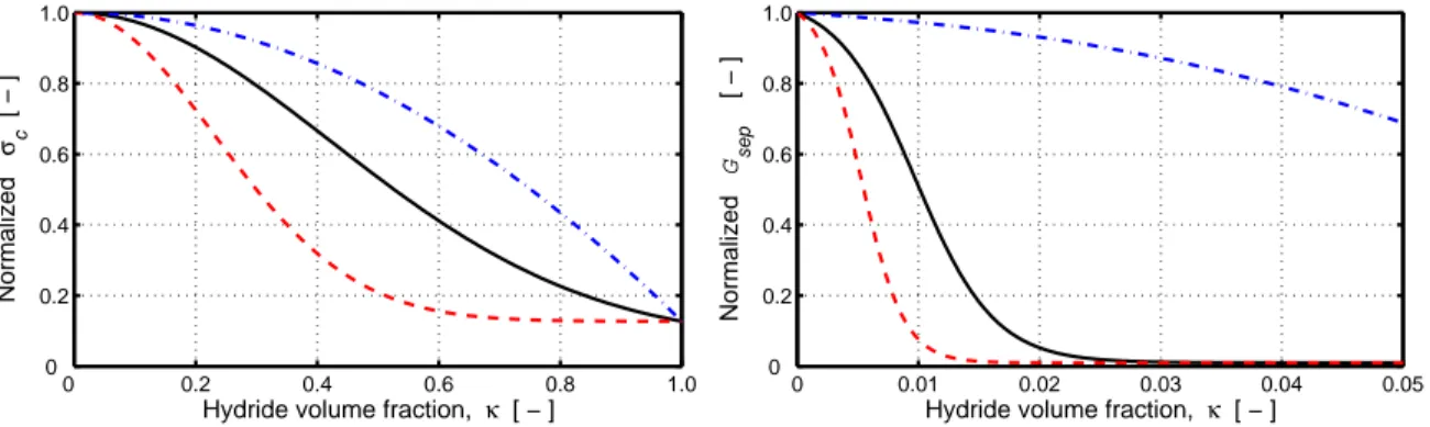
area for complete separation of the crack faces. These parameters, shown in figure 2, are closely related to the material's tensile strength and fracture toughness. They are in our model correlated to temperature, accumulated fast neutron dose, hydride volume fraction and hydride orientation with respect to the crack plane. The correlations are based on open literature data on tensile strength and fracture toughness of hydrided zirconium base cladding alloys and Zr-2.5Nb pressure tube materials. The variation of sep and σc with respect to hydride volume fraction and orientation is illustrated
for un-irradiated Zircaloy-4 at 523 K in figure 3.
Crack
δ
σ
t(δ )σ
tσ
cδ
sepFigure 2: Cohesive zone fracture model. Separation of the material at the crack front is resisted by cohesive tractions, σt,
which depend on the local crack opening, δ. The work of separation, sep, is the area below the curve for σt versus δ.
0 0.2 0.4 0.6 0.8 1.0 0 0.2 0.4 0.6 0.8 1.0
Hydride volume fraction, κ [ − ]
Normalized σ c [ − ] 0 0.01 0.02 0.03 0.04 0.05 0 0.2 0.4 0.6 0.8 1.0
Hydride volume fraction, κ [ − ]
Normalized
G
sep
[ − ]
Figure 3: Normalized cohesive strength and work of separation for un-irradiated Zircaloy-4 at 523 K, plotted with respect to hydride volume fraction and hydride orientation. Full black line - random hydride orientation, red dashed line - all hydrides parallel to the crack plane, blue dash-dotted line - all hydrides perpendicular to the crack plane.
A convenient and widely used expression for the relation between cohesive tractions and crack opening, i.e. c
in eq. (12), is furnished by the universal binding law of Smith and Ferrante [9]. This law is in our model used as a constitutive relation for planar interface elements, which are placed along a pre-defined crack plane in the finite element mesh. The finite element formulation follows the work of Ortiz and Pandolfi [10], but is in our model restricted to two dimensions and pure opening (mode I) loading of the crack.
2.6 Numerical Solution Strategy
The fundamental equations to be solved are the hydrogen transport equation, including phase transformation, and the equation for mechanical equilibrium, including hydrogen-induced deformation and fracture of hydride-rich material. These time-dependent partial differential equations are solved in two-dimensional space by use of the finite element method, and implicit time stepping (backward Euler method) is used for the discretization with respect to time. The space-time variation of temperature is supplied as input, and not calculated within the model.
The governing finite element equations for hydrogen transport and mechanical equilibrium are in each time step solved separately and in tandem. Iterations are needed in each time step to cater for the interconnection between the hydrogen transport problem and the mechanical behaviour of the structure: The solution to the hydrogen transport problem relies on stresses and stress gradients calculated in the mechanical solution, and conversely, the calculated distributions of free hydrogen, hydride volume fraction and hydride mean orientation are needed in mechanical analyses to define hydrogen-induced strains and material strength. In fact, iterations are usually needed also when this interconnection is disregarded, since the governing equations for hydrogen transport and mechanical equilibrium are, as such, non-linear. The iterations are terminated when the differences in calculated results from two successive iterations become less than user-defined tolerances. Once a converged solution is reached, the solution is advanced to a new time step. The time step length is set adaptively, so that the relative change of certain key variables from one time step to another should nowhere exceed certain pre-defined limits.
3. APPLICATIONS
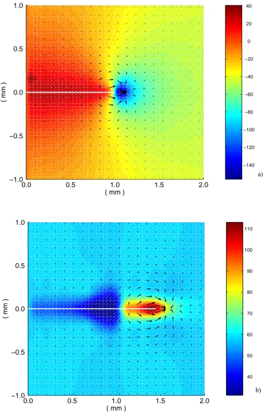
To illustrate the applicability of the presented model, we first consider a simple case of delayed hydride cracking at a uniform and constant temperature of 523 K. The analysed sample is made of unirradiated Zr-2.5Nb pressure tube material, and contains 58 wppm of uniformly distributed hydrogen. The sample contains a sharp notch, which is subjected to a constant opening (mode I) load of 15 MPam1/2. Figure 4a shows the calculated distribution of hydrostatic pressure, p, at the notch, immediately after onset of loading. The black arrows indicate the direction and magnitude of the hydrogen flux. Since both the temperature and the initial hydrogen concentration are uniform, we note from eq. (5) that the hydrogen flux is here driven solely by the gradient in hydrostatic pressure.
The stress-directed flow of hydrogen leads to precipitation of hydrides in front of the notch, and to gradual embrittlement of the near-notch material. According to our simulation, a crack starts to grow from the notch about 80 minutes after onset of loading. After roughly 3 hours, the crack attains a constant growth rate of 6.5×10⁻⁸ ms-1. This calculated steady-state growth rate is in fair agreement with the measured value of 8.86×10⁻⁸ ms-1, which is an average value of 80 identical tests in a recent international study of DHC [11]. Figure 4b shows the calculated hydrogen flux and distribution of hydrogen at the crack front, as the crack grows under steady-state conditions. Hydrides precipitate ahead of the advancing crack front and dissolve behind it, and there is a considerable flow of solute hydrogen from a region just behind the crack front to the peak stress region.
Next, we consider hydrogen-induced fracture of a corroded Zircaloy-2 cladding tube from a high-burnup fuel rod under time-varying loading conditions. The considered tube, with an as-fabricated outer diameter of 9.84 mm and a wall thickness of 605 µm, has accumulated a fast (E>1MeV) neutron dose of 5×1025 m-2. A cross-section of the tube, corresponding to an axial position at a pellet/pellet interface is considered in our calculations. The cladding tube has a particularly high hydride content at this cold-spot position, and most of the hydrides are located to a 90 µm wide rim at the cladding outer surface. The hydrogen concentration is about 4000 wppm in the rim, but only 90 wppm in the inner part of the cladding wall. Power ramp tests on high-burnup fuel rods [12] as well as out-of-pile mechanical tests [13] have shown that cladding tubes with hydrogen distributions as described above may fail by outside-in radial crack growth. Fractography of failed samples indicate that the crack growth usually takes place by DHC through the outer part of the clad wall and ends with ductile rupture of the remaining ligament [12,13].
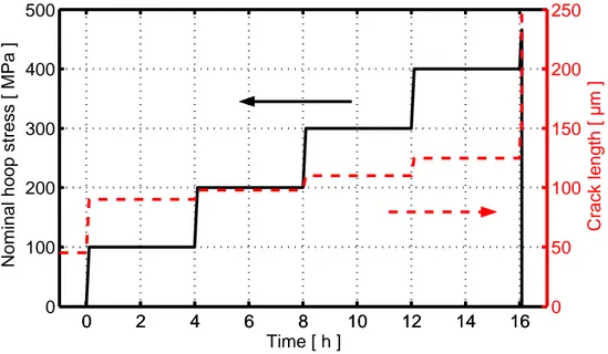
The cladding tube was in our computations loaded in a stepwise manner, where each load step lasted four hours, as shown in figure 5. The temperature was held constant at 523 K throughout the loading history. A surface flaw, initially extending halfway through the 90 µm thick hydride rim, was assumed at the cladding outer surface. This pre-existing flaw grew through the remaining part of the hydride rim as the first load step was applied, but the crack arrested at the interface to the more ductile material beneath the hydride rim. Further crack growth took place in steps, as shown in figure 5. For each rise in load, the hydrided region ahead of the crack front broke, and the crack extended by 10-25µm. When the load was increased from 400 MPa, this increment of stable crack growth was followed by unstable ductile rupture of the cladding tube at a nominal hoop stress of 470 MPa. Figure 6 shows the distribution of hydride and the flux of solute hydrogen close to the crack, just before final rupture of the tube. The densely hydrided rim to the left provides a significant source of hydrogen, and the flux pattern is much different from that in figure 4b, which is for a material with a uniform distribution of hydrogen. It should be remarked that the calculations were done for out-of-reactor conditions, i.e. we have not considered ingress of hydrogen from aqueous corrosion of the crack faces, which may contribute to the hydrogen flow under in-reactor conditions [12].
0.0 0.5 1.0 1.5 2.0 −1.0 −0.5 0.0 0.5 1.0 ( mm ) ( mm ) −140 −120 −100 −80 −60 −40 −20 0 20 40 a) 0.0 0.5 1.0 1.5 2.0 −1.0 −0.5 0.0 0.5 1.0 ( mm ) ( mm ) 40 50 60 70 80 90 100 110 b)
Figure 4: Delayed hydride cracking in unirradiated Zr-2.5Nb at 523 K. Calculated distributions of: a) Hydrostatic pressure (MPa) at onset of loading. b) Total hydrogen concentration (wppm) under steady-state crack growth. The black arrows indicate the direction and magnitude of hydrogen flux.
0
2
4
6
8
10
12
14
16
0
100
200
300
400
500
Time [ h ]
Nominal hoop stress [ MPa ]
0
2
4
6
8
10
12
14
16
0
50
100
150
200
250
Crack length [ µm ]
Figure 5: Stepwise loading history applied to the Zircaloy-2 cladding tube, together with the calculated crack length. The crack grows outside-in, starting as a 45 µm long flaw in the densely hydrided rim at the cladding outer surface.
0.0 0.1 0.2 0.3 −0.15 −0.10 −0.05 0 0.05 0.10 0.15 ( mm ) ( mm ) 2 4 6 8 10 12 14 16 18 20 22
Figure 6: Calculated distribution of hydride (volume%) close to the crack, just before final rupture of the cladding tube. The crack has propagated through the 90 µm wide hydride rim to the left and 60 µm further into the subjacent material, when unstable fracture occurs. The white arrows indicate the direction and magnitude of hydrogen flux.
4. CONCLUDING REMARKS
A few numerical models for DHC, similar to the one presented here, have been reported in open literature; see for instance the works by Lufrano et al. [14] and Varias and Massih [15]. Our model differs from these earlier models in many respects. Firstly, our model considers not only the local volume fraction, but also the orientation of hydride precipitates. The hydride volume fraction and orientation are key parameters in calculations of material strength and toughness, hydride-induced expansion, and also in calculations of hydrogen transport through the two-phase material. Secondly, we treat precipitation and dissolution of δ-hydride precipitates as diffusion controlled, time dependent processes. The hysteresis of the phase transformation is also considered, which means that the hydrogen solubility differs between heating and cooling. Another important feature of the presented model is that it applies a general constitutive relation for temperature- and stress-directed diffusion of hydrogen in a two-component composite material. In contrast to other models, it considers hydrogen diffusion not only in the metal, but also in the hydride phase. Moreover, the mean orientation of hydride precipitates is considered in calculations of the hydrogen flux: hydrogen flow is hindered by δ-hydride precipitates, and the strongest reduction is obtained when the flux is normal to the δ-hydride platelets.
The presented model is intended primarily for DHC in zirconium alloy cladding, but it can be used to study a wide range of problems involving temperature- and/or stress-directed transport of hydrogen in combination with hydride precipitation and fracture. The model treats crack initiation as well as crack propagation under both time-independent brittle failure and delayed hydride cracking of the material. It is applicable to transient load and temperature histories as well as stationary conditions, in-reactor and out-of-reactor environments, and it caters for gradients in both temperature and material properties. Arbitrary two-dimensional geometries and thermo-mechanical loading conditions can be modelled, since the finite element method is used to solve the governing partial differential equations.
REFERENCES
[1] Coleman, C. E., "Cracking of hydride-forming metals and alloys," Chapter 6.03, Comprehensive structural integrity: Fracture of materials from nano to macro, Vol. 6: Environmentally assisted failure (J. Petit and P. M. Scott, eds.), pp. 103-161, Elsevier Pergamon, 2003.
[2] Grigoriev, V. and Jakobsson, R., “Delayed hydrogen cracking velocity and J-integral measurements on irradiated BWR cladding,” J. ASTM. Int., Vol. 2(8), 2005, Paper ID JAI12434.
[3] Shi, S-Q. and Puls, M.P., “Advances in the theory of delayed hydride cracking in zirconium alloys,” Hydrogen effects in Materials (A.W. Thompson and N.R. Moody, eds.), pp. 611-621, The Minerals, Metals and Materials Society (TMS), USA, 1996.
[4] Shewmon, P., Diffusion in Solids (2nd ed.), TMS, Warrendale, PA, USA, 1989.
[5] Ham, F.S., "Stress-assisted precipitation on dislocations," J. Appl. Phys., Vol. 30(6), 1959, pp. 915-926. [6] Kearns, J.J., "Dissolution kinetics of hydride platelets in Zircaloy-4," J. Nucl. Mat., Vol. 27, 1968, pp. 64-72. [7] Northwood, D.O. and Kosasih, U., "Hydrides and delayed hydrogen cracking in zirconium and its alloys," Int.
Metals Review, Vol. 28(2), 1983, pp. 92-121.
[8] Puls, M.P., "Effect of stress on hydride reorientation in zirconium alloys," Proc. of the Int. Seminar on Solute-Defect Interaction, pp. 426-433, Kingston, Canada, August 5-9, 1985.
[9] Rose, J.H., Ferrante, J. and Smith, J.R., "Universal binding energy curves for metals and bimetallic interfaces," Phys. Rev. Lett., Vol. 47(9), 1981, pp. 675-678.
[10] Ortiz, M. and Pandolfi, A., "Finite-deformation irreversible cohesive elements for three-dimensional crack propagation analysis," Int. J. Num. Methods in Engng, Vol. 44, 1999, pp. 1267-1282.
[11] International Atomic Energy Agency, “Delayed hydride cracking in zirconium alloys,” IAEA-TECDOC-1410, IAEA, Vienna, Austria, 2004.
[12] Shimada, S., Etoh, E., Hayashi, H. and Tukuta, Y., “A metallographic and fractographic study of outside-in cracking caused by power ramp test,” J. Nucl. Mat., Vol. 327(2-3), 2004, pp. 97-113.
[13] Private communication with A-M. Alvarez-Holston, Studsvik Nuclear, Studsvik, Sweden.
[14] Lufrano, J., Sofronis, P. and Birnbaum, H.K., “Elastoplastically accomodated hydride formation and embrittlement,” J. Mech. Phys. Solids, Vol. 46(9), 1998, pp. 1497-1520.
[15] Varias, A.G. and Massih, A.R., “Hydride-induced embrittlement and fracture in metals – effect of stress and temperature distribution,” J. Mech. Phys. Solids, Vol. 50(7), 2002, pp. 1469-1510.