Model-based Testing on Generated C Code
Mälardalen UniversitySchool of Innovation, Design and Engineering Athanasios Stratis
2015-06-27
Examiner: Kristina Lundqvist Supervisor: Adnan Čaušević Co-Supervisor: Eduard Paul Enoiu
1
Abstract
In this master thesis we investigated whether it is possible to use automatically generated C code from Function Block Diagram models as an input to the CPAchecker model checker in order to generate automated test cases. Function Block Diagram is a non-executable programming and modeling language. Consequently, we need to transform this language to an executable language that can be model checked. A tool that achieves this is the MITRAC tool, a proprietary development tool used in the embedded system domain, for engineering programmable logic controllers. The purpose of this research was to investigate to what extent the generated C code using MITRAC can be reused as an input to the CPAchecker tool for automated test case generation. In order to achieve this we needed to perform certain transformations steps on the existing code. In addition, necessary instrumentations were needed in order to trigger CPAtiger, an extension of CPAchecker which generates test cases, to achieve maximum condition coverage. We showed that by performing the required modifications it is feasible to reuse the generated C code as an input to CPAchecker tool. We also showed an approach for mapping the generated test cases with the actual Function Block Diagram. We performed mutation analysis in order to evaluate the quality of the generated test cases in terms of the number of injected faults they detect. Test case generation with CPAchecker could be improved in the future in terms of reducing the number of transformations and instrumentations that are currently needed. In order to achieve this we need to add to CPAchecker tool support for structures that are used in C, such as structs. Finally we can extend the type of logic coverage criteria we can use with CPAchecker by adding additional support of FQL language.
2
List of Figures
2.1 A PLC ... 8
2.2 Internal structure of a PLC ... 9
2.3 A Function Block Diagram ... 10
2.4 CPAchecker structure ... 14
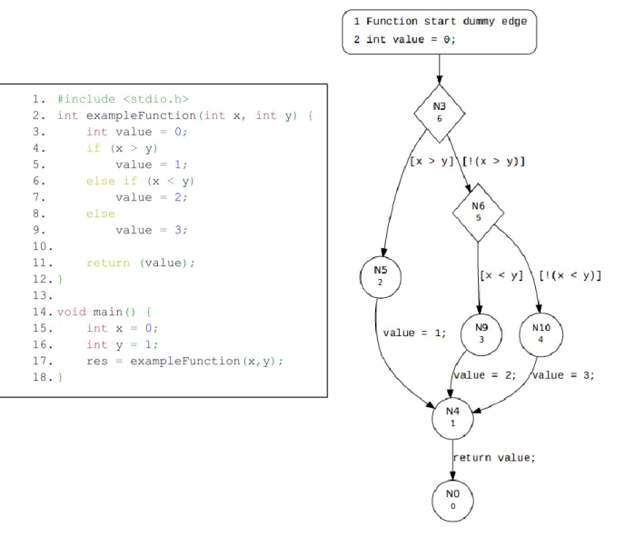
2.5 A C program and its Control Flow Automaton ... 15
2.6 A simplified C program, its CFA (center) and its ARG (right) ... 16
3.1 The research method employed in this thesis ... 18
4.1 Query-driven Program testing ... 19
4.2 A Finite automaton for covering line 7 ... 19
4.3 CPAtiger approach for generation of test cases ... 20
5.1 FBD for FAN CONTROL example ... 28
5.2 Mapping between test case 1 and FBD ... 29
List of Tables
2.1 A set of test cases for Predicate Coverage ... 112.2 A set of test cases for Clause Coverage ... 11
2.3 A set of test cases for Combinatorial Coverage ... 11
2.4 A set of test cases for Active Clause Coverage ... 12
4.1 Generated test cases by CPAtiger ... 20
5.1 Generated test cases for MSEL8_I function by CPAtiger tool ... 24
5.2 negation operation handled by instrumented code ... 25
5.3 Constant and output variables of FAN CONTROL program ... 26
5.4 generated test cases for FAN program by CPAtiger ... 28
5.5 mapping between test cases and FBD... 29
5.6 mutants that were not “killed” by CPAchecker ... 31
3
Contents
1. Introduction ... 4
1.1 Problem formulation ... 4
2. Background ... 6
2.1 Programmable Logic Controller ... 6
2.2 IEC 61131-3 standard ... 7
2.3 Function Block Diagram ... 8
2.4 Software Testing ... 9
2.4.1 Logic Coverage Criteria ... 9
2.5 Program Analysis and Model checking ... 11
2.6 CPAchecker ... 12
2.6.1 CPAtiger ... 13
2.7 Mutation testing ... 14
2.8 State of the Art ... 14
3. Research Method ... 16
4. CPAtiger and generated code by MITRAC ... 18
4.1 FShell Query Language and CPAtiger ... 18
4.2 Executing CPAtiger ... 20
4.3 The generated C code by MITRAC ... 21
5. Results ... 22
5.1 Transformation of generated C code ... 22
5.2 Code Instrumentations ... 24
5.3 Map generated test cases with FBD ... 29
6. Evaluation of results ... 30
6.1 Related research and experimental comparison ... 31
7. Conclusion ... 33
7.1 Future work ... 33
Appendix A – Code Listings ... 34
Bibliography ... 41
4
1. Introduction
Function Block Diagram (FBD) is one of the most widely used programming languages for designing safety-critical systems. It is defined within the concept of 61131-3 standard, which was established by International Electrotechnical Committee (IEC) [4]. This standard defines five programming languages that can be used for the design of Programmable Logic Controllers (PLCs), which are controllers that are used in safety-critical systems.
Since the IEC 61131-3 standard was established and succeeded in increasing the reusability of PLCs, the need for verification and validation of them was raised radically. Testing PLCs is not an easy task. The reason is that the programming languages that are defined in IEC 61131-3 standard are not executable [2]. Therefore, there is a need for transforming the software into an executable actual program code, e.g. C code, in order to be compiled and executed on the PLC.
In addition, the verification of software components for safety-critical systems is a quite significant process [3]. Consequently the phase of testing the quality and the reliability of PLCs is one of the most important ones within the PLC software development lifecycle [6]. The purpose of this phase is to minimize the chance of a critical failure due to an untraced software error [5]. This can be achieved either by creating tests manually and executing them, which is expensive and prone to human error. Alternatively, researchers have proposed the use of automated test generation using a model checker for PLC software [5].
According to Sadolewski [7], model checking is a method for formal verification of finite-state systems. Therefore, if we are able to transform one of the non-executable programming languages of IEC 61131-3 standard into the input language of one of the existing software model checkers [8] then the model checker will be able to generate automatically test cases that can eventually be executed. Consequently we will be able to validate and verify PLCs.
The purpose of this research is to investigate how FBD can be transformed into actual c code in order to be used as an input to the CPAchecker tool, which is a tool for verifying configurable software [9], so that it can generate automated test cases.
1.1 Problem formulation
This thesis report has two major goals: the first goal is to investigate and define how an FBD program can be transformed to C code. This can be used as an input to the CPAchecker tool in order for it to generate automated test cases. The second goal of this thesis is to identify a mapping between the automatically generated test cases and the actual FBD program.
Bombardier Transportation AB, which is a major rail vehicle manufacturer in Sweden, have developed a tool, called MITRAC, in order to transform an FBD program to an executable C code. This thesis investigated if the generated C code by MITRAC tool can be used as an input to the CPAchecker. We showed to what extend the generated C code can
5
meet the requirements and be transformed to a structure of C code that is accepted by CPAchecker as an input.
The test cases that CPAchecker generated are related with the C code, since this is the input that is used by the tool. The goal of this thesis is to investigate how we can relate the information we retrieve, by measuring coverage on C code, to the coverage of FBD. It is reasonable to mention that it is meaningless to map the test cases with the C code, since this is considered to be an intermediate step in verification and validation progress of FBD programs. What is significantly important is to map the generated test cases with FBD and this is what this thesis investigated.
The problem that this master thesis report will address can be formulated into the following research questions (RQs):
RQ1: How can we represent an FBD program as a C program such that it can be used by the CPAchecker tool?
RQ2: How can we instrument the C code that is used by CPAchecker for the purpose of model-checking properties related to logic-based coverage achieved FBD program? RQ3: How can we map properties which we model-check on the C code with the actual FBD program?
More specifically we investigated to what extent the C code that is generated by MITRAC tool can be reused as an input to the CPAchecker tool. In addition, we defined the modifications that are needed to be performed, in order to utilize CPAchecker.
This thesis report is organized as follows. In Section 2 we provide the necessary theoretical information that is needed in order to understand the contributions of the report. In Section 3 we describe the research method that was used in order to retrieve the results of the work while in Section 4 we provide technical information that are required in order to present the results of the work which are presented in Section 5. In Section 6 we evaluate the results of the research and we perform an experimental comparison with an existing tool for test case generation. Finally in Section 7 we summarize the results of the research and we discuss future work.
6
2. Background
In this section introduce Programmable Logic Controller and we describe its architecture. Then we present IEC 61131-3 standard and its fundamental software unit (POU). Next we describe Function Block Diagram programming language and we introduce software testing, focusing on logic coverage criteria. In addition, we discuss about two approaches for static software verification, namely model checking a program analysis and we introduce CPAchecker and its extension CPAtiger. Finally we present the related state of the art.
2.1 Programmable Logic Controller
A microprocessor–based controller is a processor, or a set of them, that based on a program and a given set of inputs will produce the required outputs, as shown in Figure 2.1 [1]. The most significant advantage that offers a microprocessor control system its reusability. This stems from the fact that by changing the program we can reuse the same microprocessor system in order to handle a broad range of different situations [1].
PLC is a type of microprocessor-based controller that uses a programmable memory in order to store the program and basic functions, namely logic, arithmetic, counting and others [1]. The primary purpose of PLC is to implement logic and switching operations. They are used widely in the industry since they are optimized for control tasks [1]. One of the most significant advantages of PLCs is reusability. It is possible to reuse the same PLC for controlling a wide variety of situations. In order to do that the engineer needs to change the program of the PLC, namely the set of instructions that will be used by the PLC in order to produce the required outputs [1]. The program is executed iteratively. Each iteration consists of three phases [3]. During the first phase the program reads and stores the inputs. In the next one it executes, which means that performs all the necessary computations in order to produce the outputs and finally during the final phase it writes the produced outputs [3].
From the hardware perspective a PLC is composed of following components [1]: Processor unit
Memory
Power supply unit Input/output interface Communication interface Programming device
7
The way that these components are connected with each other is illustrated in Figure 2.2.
The processor unit is responsible for receiving the inputs and according to the instructions of the program carry out the control actions and produce the required outputs. The
programming device is used in order to enter the program in the program and data memory. Input sections are used in order to provide information from external devices to
the CPU, while output sections are used in order for the CPU provides the outputs.
Another significant advantage of PLCs is that it is not required by the engineers to have a high level of programming language in order to enter the program that is needed for the PLC. This is done by using simple and easy to understand programming languages [1]. However in the past manufacturers were using different programming languages [2], which were costly and development time consuming. As a result of this it was quite challenging for engineers to reuse PLCs in different situations. Over the time it was clear that there is a need for a standardized programming language in order to develop programs for PLCs, so that it is possible to be used by different manufactures in different situations.
2.2 IEC 61131-3 standard
International Electrotechnical Committee (IEC) established the IEC 61131-3 standard, which is the first worldwide accepted standard, that defines, among others, a standard programming technology for PLCs [2]. It contains not only major principles for developing PLC projects but also describes the programming languages that can be used in PLCs [2]. It is used though more as a set of guidelines that should be followed in order to program PLCs.
The fundamental software unit that is defined in IEC 61131-3 is called POU (program organization unit) [2]. According to the 61131-3 standard [4], a POU can be called multiple times and contains a well-defined interface with inputs and outputs. There are three different types of POUs, namely Program (PROG), Function block (FB) and Function (FUN) [2]. Function and FB provide similar functionality. Their purpose is to produce outputs based on the input parameters that are provided. The major difference is that a FUN has no memory and therefore, if it is called with the same inputs it will provide the
Figure 2.2 – Internal structure of a PLC [1]
8
same outputs. On the other hand, FB has its own data record [2]. Programs (PROG) can be seen as the main program of a PLC.
IEC 61131-3 standard defines a huge amount of details [2]. Therefore, it is quite hard for a programming system to implement all the standard. Thus, programming systems usually implement a part of it. There are three different levels that certificate the compliance of a programming system with the standard, namely Base Level (BL), Reusability Level (RL) and Conformity Level (CL) [2].
The programming languages that are defined in IEC 61131-3 standard are as follows: Structured Text (ST), Function Block Diagram (FBD), Ladder Diagram (LD), Instruction List (IL) and Sequential Function Chart (SFC) [2]. ST and IL are textual programming languages. On the other hand, FBD, SFC and LD are graphical ones [2].
2.3 Function Block Diagram
Function Block Diagram is a graphical programming language which is widely used in industry in order to design PLCs [2]. It describes the relation between input parameters and output variables. The parameters are given as inputs to the graphical elements. The result is calculated by the graphical elements and stored in an output variable which is then ready for sending to the next graphical element [2]. This data flow is described by graphical elements which are connected with each other with connection lines, as illustrated in Figure 2.3.
A graphical element can be either a function that implements basic operations, such as logarithmic, conversion etc., a function block, e.g. counter, timer or a function that implements a required task [1].
In Figure 2.3 the FBD consists of 3 blocks, which perform basic bitwise operations. The first block has two inputs, namely input 1 and input 3 and performs the bitwise AND operation. Input 3 is used as an input parameter in the second block as well, which has an additional input parameter, namely input 2 and performs bitwise OR operation. The
9
results of these two blocks are sent as output variables to the third block, which performs the bitwise XOR operation and provides the final output of the FBD.
2.4 Software Testing
Software testing is a significant phase in software development lifecycle process [10]. It is an expensive and time consuming process and needs more than 50% of the overall software development cost [10]. This percentage is even higher for the development of safety-critical systems. The purpose of software testing is to execute the software under testing and compare the result of the execution against the expected one in order to conclude whether the implemented software meets its specification or not. According to Ammann et al. [10] and Utting et al. [11], software testing is a process that proves the presence of failures but not their absence. In order to evaluate how thorough is a test case, or a set of test cases, we use coverage criteria [3]. The coverage score of a set of test cases is calculated by using the equation (2.1):
𝐶𝑜𝑣𝑒𝑟𝑎𝑔𝑒𝐴𝐶 = |𝑇𝑒𝑠𝑡𝑒𝑑𝐴𝐶(𝑇, 𝑆)|
|𝐸𝑥𝑖𝑠𝑡𝑖𝑛𝑔𝐴𝐶(𝑆)| (2.1)
It represents how many of the existing test items, 𝐸𝑥𝑖𝑠𝑡𝑖𝑛𝑔𝐴𝐶(𝑆) , have been tested, namely 𝑇𝑒𝑠𝑡𝑒𝑑𝐴𝐶(𝑇, 𝑆).
2.4.1 Logic Coverage Criteria
Logic coverage criteria are used in order to test the logical expressions of the software artifact. Logical expressions are widely used in every software artifact, such as source code, state machines etc. [12]. In addition, it is easy to evaluate them automatically and simply to formalize [12]. Therefore, there are many coverage criteria that are defined and used in order to test logical expressions.
In order to control the flow of an FBD program we use Boolean variables and logical expressions which are composed of Boolean variables and Boolean operators (AND, OR etc.) [3]. Therefore, in order to assess the thoroughness of a set of test cases, that cover FBD programs, we use logic coverage criteria. There are several logic coverage criteria. The most commonly used are the Predicate Coverage (PC), Clause Coverage (CC), Combinatorial Coverage (CoC), Active Clause Coverage (ACC) etc. In order to understand the logic behind these criteria first we need to define predicate and clause.
A predicate is a logic expression that evaluates to TRUE or FALSE. According to Ammann et al. [10], a predicate can be composed of Boolean variables, non-Boolean variables which are compared by using the required operators (<, >, ≤, ≥, =, ≠) and function calls. We use mathematical symbols in order to formalize logical expressions [10].
A clause is a predicate which does not contain any logical operators. The following expression (2.2) is a predicate, which consists of three clauses, namely a Boolean variable (A), a comparison expression (𝑏 ≥ 𝑐) and a call function 𝑓(𝑥, 𝑧) that returns a Boolean variable.
10
Predicate Coverage (PC), which is also referred as decision coverage, assesses if each predicate of the software artifact is evaluated to TRUE and FALSE. A set of test cases that satisfies predicate coverage for the predicate (2.2) is illustrated in Table 2.1.
ID A 𝑏 𝑐 𝑓(𝑥, 𝑧) Result
1 T 1 0 T T
2 T 0 1 F F
A drawback for this type of coverage criterion is that it is possible that one or more individual clauses are not always evaluated to both TRUE and FALSE at least once [12]. In the above mentioned example the first clause, namely A, is always evaluated to TRUE. In order to address this problem we use clause coverage.
Clause Coverage (CC), which is also referred as condition coverage, assesses if each clause of every predicate in the software artifact is evaluated to TRUE and FALSE [3]. A test suit that satisfies clause coverage for the predicate (2.2) is illustrated in Table 2.2.
ID A 𝑏 𝑐 𝑓(𝑥, 𝑧) Result
1 T 1 0 T T
2 F 0 1 F F
Combinatorial Coverage (CoC), assesses if each clause of every predicate in the software artifact is evaluated to each possible combination of truth values [10]. CoC is considered to be impractical logic coverage criterion because we need a considerable amount of test cases for predicates with several clauses. The reason is that a predicate 𝑝 with 𝑛 clauses has 2𝑛 possible assignments of truth values [10]. For instance the predicate (2.2) contains three clauses. Therefore, we need 8 different test cases, which are illustrated in Table 2.3.
ID A 𝑏 𝑐 𝑓(𝑥, 𝑧) Result 1 T 1 0 T T 2 T 2 1 F T 3 T 0 1 T F 4 T 1 2 F F 5 F 2 2 T F 6 F 2 0 F F 7 F 0 3 T F 8 F 1 3 F F
Active Clause Coverage (ACC), which is also referred as Modified Condition / Decision Coverage (MC/DC), assesses whether each major clause of every predicate in the software artifact determines the final value of the predicate to TRUE and FALSE [12]. Major clause is the clause that the test case is focused on, while the values of the other clauses remain
Table 2.1 – A set of test cases for Predicate Coverage
Table 2.2 – A set of test cases for Clause Coverage
11
unchanged. Thus, the goal of ACC is to change the value of the predicate when the value of the major clause is changed [12].
In the predicate (2.3) we will consider the first clause as major clause (A) and we will determine the value of the predicate based on the values of the major clause.
(𝐴 ∨ 𝑓(𝑥)) ⋀ (𝑖 = 𝑗) (2.3)
This is illustrated by test cases 1 and 2 in Table 2.4. Next we consider as the major clause the function 𝑓(𝑥). Therefore, we hold the same values for the remaining clauses and we determine the final value of the predicate based on the value of the major clause. This is shown by the test cases 3 and 4 in Table 2.4. We follow the same procedure for the final clause. Therefore, the Table 2.4 is as follows:
ID A 𝑓(𝑥) 𝑖 𝑗 Result 1 T F 0 0 T 2 F F 1 1 F 3 F T 0 0 T 4 F F 1 1 F 5 T T 2 2 T 6 T T 0 1 F
We notice that test cases 2 and 4 are identical. Therefore, the final test cases we need in order to satisfy ACC for the predicate (2.3) are 1,2,3,5 and 6.
2.5 Program Analysis and Model checking
As it was mentioned in section 2.4, during the testing process we verify whether the software satisfies its specification by comparing the result of its execution against the expected one. In order to conclude whether the software meets its specification or not we have to determine the right test cases. Thus, is achieved by identifying the appropriate input parameters and the appropriate test oracle for each test case. This procedure is error prone, time-consuming and expensive when it is performed manually [5]. Therefore, we need to verify the program automatically.
The method that will be used in order to verify the program automatically needs to be decisive, in order to reveal as less as possible false positives [13]. But the more precise the method is, the more expensive it will be. The two most common methods of static verification are model checking and program analysis. Both of these two methods reflect the trade-off between precision and efficiency [13]. Program analysis is used to understand the behavior of the software and is more efficient approach comparing to model checking. On the other hand, model checking checks whether the model of a software meets its specification or not and focuses on correctness [9, 13]. The algorithms that are used in model checking investigate the reachable states of the software [13]. If the algorithm reveals a state that does not satisfy the property, then a counterexample will be produced. The counterexample is a trace that exposes the error and is used to trace back the error in the model [13].
12
These two approaches are considered to be subcase of the other [13]. Therefore, the researchers are trying to combine them by exploiting the efficiency of program analyzers and the precision of model checkers [13]. Thus, they extended the model checker BLAST [13], by developing CPAchecker, which gives the opportunity to the researchers to configure the automated software verification process.
2.6 CPAchecker
CPAchecker is an open-source framework that is used for configurable analysis and verification of programs written in C programming language [9]. It combines the concept of model checking and different approaches of program verification in one framework. Therefore, the researchers are able to compare experimental results of different approaches or the combination of them [9]. Figure 2.4 illustrates the way that CPAchecker works.
The input of the tool is a program written in C. CPAchecker transforms this program into Control-Flow Automata (CFA) and based on the type of program analysis the researcher selected the algorithm of the tool that will provide the verification results [9]. CFA is a directed graph that consists of finite set of nodes and edges [14]. Each node represents a program counter and each edge represents a program operation [14]. A transformation
13
of a simple program in C into CFA created by CPAchecker is shown in Figure 2.5. The main algorithm of the tool performs reachability analysis on the program [9], which means that it computes all the states of the program that are reachable.
The architecture of the tool is component-based, which means that it is easy to extend by integrating new components. Therefore, the researchers developed an extension of the tool, which is called CPAtiger, in order to generate test cases for the input program [9].
2.6.1 CPAtiger
CPAtiger is a test case generator based on CPAchecker. It performs reachability analysis similarly to CPAchecker in order to derive the appropriate test inputs [15]. The algorithm that CPAtiger executes in order to find the test inputs is based on model checking. More specifically the idea that the algorithm implements, is to derive a counterexample by the model checker, which will be used as a test input. This is achieved by using the test goal as an input to the model checker [15, 16]. Given the CFA of the input program, which is
1. #include <stdio.h>
2. int exampleFunction(int x, int y) { 3. int value = 0; 4. if (x > y) 5. value = 1; 6. else if (x < y) 7. value = 2; 8. else 9. value = 3; 10. 11. return (value); 12. } 13. 14. void main() { 15. int x = 0; 16. int y = 1; 17. res = exampleFunction(x,y); 18. }
14
generated by CPAchecker, the location of the CFA that we want to derive a test input and the predicate we want to test, the algorithm is trying to find a path in the CFA in order to reach the required location [15]. Then it derives the test inputs by finding values that satisfy the path that is previously found [15]. In order to achieve this CPAtiger uses an abstract reachability graph (ARG) [15]. An ARG is a directed graph which consists of a finite set of nodes and edges [17]. Each node of the ARG represents an abstract state. In order to create the abstract states we compute the abstract successor states based on the respective edges on the CFA of the program [17]. Each edge represents a program operation. An ARG for the program shown in Figure 2.5 is illustrated in Figure 2.6.
2.7 Mutation testing
Mutation testing is a technique that is used in order to evaluate the quality of the generated test cases in terms of the number of faults that they can detect. In principal it can be used for several types of artifacts but the engineers usually use it for program code [10]. According to this technique first we generate test cases for a program under test. Afterwards we create faults that we instrument into the existing program. Each version of modified program contains only one fault and is called mutant. Then for each mutant we execute again the test cases and we observe the results. If some of the test cases failed, this means that these test cases managed to detect the fault we instrumented on purpose. Then we say that the test case “killed” the mutant. The more mutants are killed by a test cases the more effective the test cases is considered to be. In order to measure the effectiveness of the test cases we define the mutation score as shown in equation (2.2):
𝑀𝑢𝑡𝑎𝑡𝑖𝑜𝑛 𝑠𝑐𝑜𝑟𝑒 = 𝐾𝑚 𝑀
(2.2) 𝐾𝑚 is the number of mutants that were killed and 𝑀 is the total number of mutants. Mutation testing will be used in order to evaluate the results of this thesis and perform an experimental comparison with an existing test case generation tool.
2.8 State of the Art
The first researchers that proposed the use of model checkers in order to generate test cases were Callahan [25] and Engels [26]. Rayadurgam and Hemindahl in [27] proposed
1. int x; 2. x = 5; 3. if (y > 1); 4. z = 2; 5. else 6. z = 2 * x / 5;
Figure 2.6 – A simplified C program, its CFA(center) and its ARG (right) [17]
15
an approach for test case generation by using counterexamples that are created by a model checker. In [28] Ammann, Black and Ding suggested a method in which specifications are mutated and then we use these mutants with a model checker in order to generate test cases. Srivatanakul in [29] applied this approach.
On the other hand, extensive research has been performed regarding static analysis of a program and tools that perform formal verification. D’ Silva, Kroening and Weissenbachen in [30] created a survey in which three of the most important methods for software verification has been described, namely abstract static analysis, model checking and Bounded Model Checking.
Furthermore, different approaches regarding FBD testing have been proposed. In [31] Richter and Wittig present an approach where the FBD program is simulated. Moreover, Baresi in [20] discuss how we can verify directly the initial FBD. Three test coverage criteria for FBD have defined by Jee at [16], while Enoiu on [3,5] suggests an approach with which we can generate automated test cases for FBDs.
16
3. Research Method
Figure 3.1 illustrates the basic steps that were followed in order to retrieve the results of the thesis. The thesis process starts by formulating the research questions. Then an extensive research was conducted at Mälardalen University. This research aimed on finding and gathering all the state of the art and current practices that could be used in order to answer the questions that previously was stated. Afterwards we conducted the required analysis of the generated code by MITRAC tool in conjunction with the analysis of the input code in CPAchecker. Then we formulated the modifications that were needed in order to achieve our goals.
Moreover, experimentation was conducted in order to evaluate our results. We investigated how we can transform FBD to c code that can be used as an input to the CPAchecker tool. This could lead us to three different cases. In the first case, the c code that is generated by the MITRAC tool that is used in Bombardier AB meet the requirements and the structure that is needed and can be used directly as an input to the CPAchecker. In the second case we need to transform the generated code by MITRAC to an accepted model in order be used as an input to CPAchecker. In the third case the generated code cannot be used as an input at all, which will leads us to the conclusion that
17
the CPAchecker cannot be used in order to generate test cases for FBD programs. Furthermore, we will investigate how the generated test cases can be mapped to the initial FBD program. Then we will evaluate effectiveness and efficiency compared to another model checker tool, namely Uppaal. Finally the results of the experimentation will be analyzed and discussed to the thesis report.
18
4. CPAtiger and generated code by MITRAC
4.1 FShell Query Language and CPAtiger
FShell Query Language (FQL) [18] is a test specification language that is used in order to specify the coverage criteria of a program under testing. It was developed as an attempt to improve the quality of the generated test cases in terms of the number of test goals that needs to be covered [19]. Its principles are based on query-driven program testing, where there is a clear separation between the specification of test goals and the test cases generation technique [19]. The test case generation back-end tool that follows the query-driven program approach needs two inputs. The first one is the source code of the program under test and the specification of the coverage criterion, which are written in FQL. Given these two inputs the tool will generate a set of test cases, as illustrated in Figure 4.1 [21].
FQL syntax is based on regular expressions. This will be illustrated by a simplistic example. For instance, given the program presented in Figure 2.5, we need a test case which will cover line 7. According to Holzer [19], we can express the path that we need to follow in order to reach line 7 by using the following regular expression
_*.@7._* (4.1)
where we describe all program executions that will reach line 7. The expression _* denotes all sequence of statements, that need to be executed before and after line 7 [19]. Symbol @ is used in order to express the number of line we want to test. An automaton that would accept our criterion is presented in the Figure 4.2.
In order to express the above mentioned criterion in FQL we write the following command:
cover “ID*.@7.ID*” (4.2)
The test goal is defined as the path that needs to be followed in order to fulfill the coverage criterion that is defined in the command. For instance for the command (4.2) the test goal is the path that needs to be followed in order to reach at line 7 of the program. A test case
Figure 4.2 – Finite automaton for covering line 7 Figure 4.1 – Query-driven Program testing [19]
19
that would be generated in order to cover the above mentioned criterion would have as input values 𝑥 = 0 and 𝑦 = 1 . We notice that this command is quite similar with the logical expression (4.1). The main difference is that we replaced the underscore _ with ID, which denotes the ID of the edge that need to be visited. Following the rules of regular expressions and using the operators “+”, ”*” and ”.” we can express more complex criteria in FQL. In addition, FQL supports filter functions with which we can express coverage criteria, such as statement coverage, condition coverage etc. [18]. For example the command (4.3) in FQL
cover “ID*.@BASICBLOCKENTRY.ID*” (4.3)
will generate a set of test cases that fulfil statement coverage.
For complex programs expressing coverage criteria in FQL results in a huge set of test goals [19]. As a backend tool we can use a model checker which will generate test cases by following query-based program testing. However, according to Holzer in [19], model checkers are not the optimal solution because for a large set of test goals they respond poorly. The reason is that the model checker needs to perform an extensive and costly run for each test goal [19]. On the other hand, expressing coverage criteria in FQL results in a big amount of test goals, which are represented as finite automaton. These finite automaton are called test-goal automaton (TGA) [19]. Based on the CFA of the program under test and the TGAs that are generated based on the FQL query, CPAtiger tool performs reachability analysis for each TGA, determining whether the TGA is feasible on the given input program or not. If yes, the CPAtiger generates a test input for this TGA [19]. This procedure is iterative until all the TGAs are checked, which will result in a set of test cases as illustrated in Figure 4.3.
20
4.2 Executing CPAtiger
CPAtiger can be used either on Windows or on Linux. For this thesis we executed it on Linux by using the terminal. In the command line we specify the type of coverage criterion we want to use to test the program, which is expressed in FQL and then we type the program we want to test, as illustrated in the Listing 4.1.
CPAtiger does not support all FQL filter functions though. The filter functions that support is only BASICBLOCKENTRY and CONDITIONEDGE which can be used in order to fulfill statement coverage and condition coverage respectively. Assuming we want to fulfill condition coverage for the program illustrated in Figure 2.5 CPAtiger would provide the following results, as shown in Listing 4.2.
First CPAtiger determines the number of test goals. As we mentioned in section 4.1 during this procedure CPAtiger generates the set of TGA. Then it performs reachability analysis for each of them and finally it generates the set of test cases that fulfill to coverage criterion we expressed in the command. CPAtiger provides information for each test goal. We can see if the test goal is feasible or not, if it is covered by an existing test case and the time that is needed in order to perform reachability analysis. Then it presents the
scripts/cpatiger.sh -fql 'COVER "EDGES(ID)*".EDGES(@CONDITIONEDGE)."EDGES(ID)*"' examples/MSEL8_I.c
Listing 4.1 – CPAtiger command line example
COVER "EDGES(ID)*".EDGES(@CONDITIONEDGE)."EDGES(ID)*" Determining the number of test goals ...
Number of test goals: 4 TODO: reduce coupling! Goal #1 is feasible! Goal #1 needed 201 ms Goal #2 is feasible! Goal #2 needed 25 ms
Goal #3 is covered by an existing test case! Goal #4 is feasible!
Goal #4 needed 45 ms Time in reach: 0.246 Max time in reach: 0.188 s Mean time of reach: 0.082 s Generated Test Cases:
p[__VERIFIER_nondet_int,-1,0][__VERIFIER_nondet_long][__VERIFIER_nondet_uint] [__VERIFIER_nondet_bool][__VERIFIER_nondet_char] p[__VERIFIER_nondet_int,1,0] [__VERIFIER_nondet_long][__VERIFIER_nondet_uint] [__VERIFIER_nondet_bool][__VERIFIER_nondet_char] p[__VERIFIER_nondet_int,0,0][__VERIFIER_nondet_long][__VERIFIER_nondet_uint] [__VERIFIER_nondet_bool][__VERIFIER_nondet_char] INTERN: #Goals: 4 #Feasible: 4 #Infeasible: 0 #Imprecise: 0 #BugRevealing: 0
21
generated test cases and finally it shows the number of feasible and infeasible test goals. In this example CPAtiger generated 3 test inputs, which are presented in Table 4.1.
ID x 𝑦 Result
1 -1 0 2
2 1 0 1
3 0 0 3
4.3 The generated C code by MITRAC
As we mentioned in previous section, Bombardier AB developed a tool called MITRAC in order to transform FBD to executable C code. In this section we will present an example of the generated code and we will illustrate all the obstacles that need to be encountered in order the code to be used as an input to the CPAtiger tool. MSEL8_I function block is written in ST and it is presented in Listing A.1 of Appendix A. It is part of an FBD which describes a component that is used in Train Control and Management System (TCMS)1. MSEL8_I function block selects the first active value in list of 8 (active, value) pairs. The generated C code by MITRAC is presented in Listing A.2 of Appendix A.
In order to reuse this code as an input to the CPAchecker tool we need to overcome specific obstacles. These obstacles are mostly related with the structure of the C code that CPAtiger tool expects as an input in order to generate test cases that will fulfill logic coverage criteria. MITRAC tool handles blocks that perform logical operations in a specific way. It transforms the logical operation to a simple statement. This needs to be changed for the CPAchecker tool. The reason is that CPAchecker tool does not recognize this kind of statements as logical conditions and therefore, it does not generate test case in order to cover it. Furthermore, obstacles related with CPAchecker needs to be encountered. More specifically, CPAtiger does not support structures that are commonly used in C programming. In addition, the logical negation operation is not supported. Therefore, we need to investigate how we can tackle these obstacles in order to achieve our goal.
1
http://www.bombardier.com/en/transportation/products-services/propulsion-controls/products/train-control-and-management-system.html
22
5. Results
In this section we will show how we can reuse the generated C code by MITRAC as an input to CPAtiger tool. In order to achieve this we need to perform specific transformations to the generated C code. In addition, we need to instrument snippets of code to trigger CPAtiger to generate the test cases we need in order to achieve 100% condition or statement coverage.
5.1 Transformation of generated C code
As we mentioned in section 4, CPAtiger does not support structures, which are commonly used in C code. Therefore, we need to perform specific transformations in the code in order to tackle this problem. Algorithm 1 illustrates the steps that need to be performed in order to achieve this. The parameter that is passed in the algorithm is the program under testing.
Algorithm 1 structTransformation(program P) 1: for each struct in the Program P do
2: for each variable defined in the struct do
3: define the variable of the struct as a variable in the test case function
4: delete the struct variable which is defined as parameter of the function
5: add the variable as a parameter to the definition of the function under
testing
6: add the variable as a parameter to call the function under testing 7: find all the statements of the program that the variable is used 8: for each statement do
9: replace the variable of the structure with the corresponding
variable we defined in the test case function 10: end for
11: delete the variable in the struct
12: end for
13: delete the struct
14: end for
The algorithm begins by selecting each of the structs that are declared in the program (line 1). Then it defines each of the variables of the struct as simple variables in the test case function and add this variable as a parameter to the function that we are currently testing (lines 3 to 6). Afterwards we need to find all the statements that the variable is using in order to replace it with the simple variable we defined in the test case function and then delete the variable that is defined in the struct (lines 7 to 12). This procedure is iterative for every variable of each struct in the program. We will illustrate step by step how the structTransformation method is performed on the MSEL8_I function block. As shown in Listing, A.2 this function block contains a struct namely MWT_MSEL8_I. In this struct 19 variables are defined. The algorithm starts with the first variable that is defined, namely MWT_BOOL ENABLE. MWT_BOOL is a struct that we assume that has been handled previously by CPAtiger since MSEL8_L constitutes a part of the FBD. We will define a variable called ENABLE type of bool in the TestCase function as shown in listing 5.1.
23
__VERIFIER_nondet_bool() is the function that is called in order to assign a number to the variable. In case this variable is Boolean then __VERIFIER_nondet_bool() will assign 0 as equivalent to FALSE and a non-zero value as equivalent to non-zero according to the C convention. Next we need to delete the variable which is defined as parameter to the function (MWT_MSEL8_L* data) and add this variable as a parameter to the MSEL8_L function in its definition. In addition, we need to add the variable as a parameter to the MSEL8_L function where it is called. This is illustrated in Listing 5.2.
Afterwards we need to find all the statements that the ENABLE variable is used. In C the variables of a struct are used in the form of “name_of_struct->name_of_variable”. Thus, we need to find statements were data->ENABLE is used and replace it with ENABLE. This is shown in Listing 5.3.
Listing 5.3 – replace variable in the statements where it is used
Then we delete the definition of the variable in the struct and we repeat this procedure for every variable that is defined in the struct. The result of the necessary transformations is illustrated in Listing A.3. In order the code to be executable, we added the definition of a struct for handling the Boolean variables.
We used the transformed code of MSEL8_I function, which is presented in Listing A.2 of Appendix A, as an input to the CPAtiger tool in order to fulfill condition coverage. The generated test cases are illustrated in Table 5.1.
1. void TestCase(){ 2.
3. bool ENABLE = __VERIFIER_nondet_bool();
Listing 5.1 – Define the variable of the struct as a variable in the test case function
1. void MSEL8_I (bool ENABLE){ … }
2.
3. void TestCase(){ 4.
5. bool ENABLE = __VERIFIER_nondet_bool();
6. MSEL8_I (ENABLE);
Listing 5.2 – add the variable as a parameter to the function
1. void MSEL8_I (MWT_MSEL8_I* data) 2. {
24 Test case ENA BLE A CTI V E_1 A CTI V E_ 2 A CTI V E_ 3 A CTI V E_ 4 A CTI V E_ 5 A CTI V E_6 A CTI V E_7 A CTI V E_8 V A LUE _1 V A LUE _2 V A LUE _3 V A LUE _4 V A LUE _5 V A LUE _6 V A LUE _7 V A LUE _8 1 T F T T T T T T T 30 27 23 19 15 11 7 3 2 T F F F T T T T T 28 25 22 19 15 11 7 3 3 T F F F F F F F F 2 3 4 5 6 7 8 9 4 F T T T T T T T T 10 11 12 13 14 15 16 17 5 T F F F F F F T T 22 25 19 16 13 10 7 3 6 T F F F F F T T T 26 23 20 17 14 11 7 3 7 T F F F F T T T T 27 24 21 18 15 11 7 3 8 T F F T T T T T T 29 26 23 19 15 11 7 3 9 T T T T T T T T T 24 21 18 15 12 9 6 3 10 T F F F F F F F T 24 21 18 15 12 9 6 3 11 T F F F F F F F T 4 5 6 7 8 9 10 11 5.2 Code Instrumentations
The algorithm that was described in the previous section will give us the opportunity to handle structs, which are not supported by CPAtiger, and thus, reuse the generated C code by MITRAC tool. Despite this, in order to take advantage of the use of CPAtiger we need to instrument snippets of code which will handle comparisons and logical operations. In FBD we can have function blocks that perform comparisons similar to the usual comparisons that are made in C. Therefore, we have a function block with two inputs which checks if the first input is greater, or less, or equal etc., than the second one. These function blocks are handled in MITRAC tool by assigning the result of the comparison to a Boolean variable as shown in Listing 5.4, where we compare if localvar_2_2_3 is greater or equal to variable P2. The result of the comparison is stored in localvar_2_3_4.
In addition, in FBD we can have function blocks which perform logical operations, such as logical AND or OR. These operations are handled in a similar way by the MITRAC tool. It generates a statement in which the result of the logical operation is stored in a Boolean variable. Therefore, we will handle these two above-mentioned cases in a similar way. Let 𝑜𝑝𝑒𝑟 ∈ {=, <, >, ≤, ≥, ≠, 𝐴𝑁𝐷, 𝑂𝑅} and var1 and var2 be the variables that we want to perform the operation. Let also var3 be the variable that MITRAC tool stores the result of the operation. Then for each statement in which one of the above mentioned operations is performed we need to add the following snippet of code which is illustrated in Listing 5.5.
1. localvar_2_3_4 = (localvar_2_2_3 >= P2);
Listing 5.4 – comparison operator handled by MITRAC tool
25
Furthermore, FBD language contains a function block type which performs the logical negation NOT. This operation returns the opposite Boolean value of the given input. For example if the input is TRUE then the output of this function block will be FALSE. This operation in MITRAC tool is handled by using the following statement as illustrated in Listing 5.6.
Statements which are written similarly to the statement presented in Listing 5.6 are not supported by CPAtiger. Thus, we need to delete these statements and instrument code that will perform the negation operation. Let var2 be the Boolean variable that we want to perform the negation operation. Then the code that we need to instrument is shown in Listing 5.7.
Table 5.2 shows how the code of Listing 5.7 performs the negation operation for a variable var2 which is evaluated either to TRUE or FALSE.
ID var2 !var2 !var2 && var2 !var2 && !var2
1 T F F -
2 F T - T
1. var3 = (var1 oper var2);
2. if (var3){
3. //statements…
4. }
Listing 5.5 – Code instrumentation for comparison and logical operations
1. DBC_A_AirDryerCtrl_0 = (!Enable_DBC_A);
Listing 5.6 – negation operation handled by MITRAC tool
1. if (var2) 2. {
3. var1 = (!var2 && var2);
4. }else
5. {
6. var1 = (!var2 && !var2);
7. }
Listing 5.7 – code instrumentation for negation operation
26
The motivation behind these instrumentations is that we want to trigger CPAtiger to perform condition coverage. In order to do that CPAtiger has to find an IF statement condition in order to execute it and generate all the required test cases that will evaluate it to TRUE and FALSE.
We will illustrate the above-mentioned instrumentations with an example. FAN CONTROL is an industrial program example provided by Bombardier Transportation AB. It consists of one integer variable, namely DBC_PV_X_CoStep, which is the input in the FBD. It also contains ten constant integers and six Boolean variables which are the outputs of the program and are presented in Table 5.3
Constant variables Output variables 1 P_Fan1Lo_1 = 3 DBC_PV_C_Fan1Lo 2 P_Fan1Lo_2 = 7 DBC_PV_C_Fan1Hi 3 P_Fan1Hi = 8 DBC_PV_C_Fan2Lo 4 P_Fan2Lo_1 = 4 DBC_PV_C_Fan2Hi 5 P_Fan2Lo_2 = 6 DBC_PV_C_Fan3Lo 6 P_Fan2Hi_1 = 7 DBC_PV_C_Fan3Hi 7 P_Fan2Hi_2 = 8 8 P_Fan3Lo = 5 9 P_Fan3Hi_1 = 6 10 P_Fan3Hi_2 = 8
The FBD of the FAN CONTROL is presented in Figure 5.1. It consists of function blocks which perform comparisons between the given input and the constant variables and logical operations. The instrumented code for the FAN CONTROL program is illustrated in Listing A.4. We used the code presented in A.4 as an input to the CPAtiger tool and the set of test cases that it generated is shown in Table 5.4.
27
28 Test case DBC_PV_X_CoStep DBC_PV_ C_Fan1L o DBC_PV_ C_Fan1Hi DBC_PV_C_Fan2L o DBC_PV_ C_Fan2Hi DBC_PV_C_Fan3L o DBC_PV_ C_Fan3Hi 1 5 T F T F T F 2 4 T F T F F F 3 7 T F F T F T 4 2 F F F F F F 5 8 F T F F F T 6 9 F F F F F F 7 3 T F F F F F
Figure 5.1 illustrates the mapping between test case 1 and the blocks of the FBD. On each line it is stated whether the test case evaluates the block to TRUE or FALSE.
Table 5.4 – generated test cases for FAN program by CPAtiger
29
5.3 Map generated test cases with FBD
Since we managed to reuse the C code (by performing the necessary transformations and instrumentations) that is generated by MITRAC tool as an input to CPAtiger tool and generate test cases that fulfil logic coverage criteria. Now we are interested in investigating how we can map the generated test cases with the actual FBD. More specifically we are interested in finding which test case evaluates which function block in the FBD to TRUE and which one to FALSE. Thus, we will be able to retrieve significant information related with the extent of the logic coverage we achieved through the generated test cases.
In order to achieve this we need to construct a table. Each row in the table will represent a block of the FBD under test, while each column will represent a test case. Then we need to check whether the test case evaluates the if statement, that corresponds to each block of the FBD, to TRUE or FALSE and fill the corresponding cell. Once we iterate the same procedure for each of the test cases we will have a complete mapping between them and each of the blocks in the FBD. The above mentioned procedure can be illustrated in the FAN CONTROL example. The table with the FBDs and the generated test cases is illustrated in Table 5.5. Block in FBD Test case 1 Test case 2 Test case 3 Test case 4 Test case 5 Test case 6 Test case 7 DBC_PV_X_CoStep >= P_Fan1Lo_1 T T T F T F T DBC_PV_X_CoStep >= P_Fan1Lo_2 T T T F F F T AND block with DBC_PV_C_FAN1Lo output T T T F F F T
DBC_PV_X_CoStep == P_Fan1Hi F F F F T F F
DBC_PV_X_CoStep >= P_Fan2Lo_1 T T T F T F F DBC_PV_X_CoStep <= P_Fan2Lo_2 T T F F F F T AND block with DBC_PV_C_FAN2Lo output T T F F F F F DBC_PV_X_CoStep >= P_Fan2Hi_1 F F T F T F F DBC_PV_X_CoStep <= P_Fan2Hi_2 T T T F F F T AND block with DBC_PV_C_FAN2Hi output F F T F F F F
DBC_PV_X_CoStep == P_Fan3Lo T F F F F F F
DBC_PV_X_CoStep >= P_Fan3Hi_1 F F T F T F F DBC_PV_X_CoStep >= P_Fan3Hi_2 T T T F T F T AND block with DBC_PV_C_FAN3Hi output F F T F T F F
30
6. Evaluation of results
The primary purpose of this research was to investigate whether it is feasible to reuse the generated C code by MITRAC tool as an input to the CPAchecker tool in order to generate test cases and to investigate what transformations and instrumentations are needed in order to achieve this. If this was feasible then we wanted to map the generated test cases with the FBD. The motivation behind this research was that we want to generate test cases that will fulfill logic coverage criteria for FBDs. We believe that creating automatically test cases for the generated C code by MITRAC, which is a transformation of an FBD will achieve this.
Based on the research that has been performed we can answer to RQ1 and RQ2 by stating that it is possible to reuse the generated C code by MITRAC as an input to the CPAchecker tool. In order to achieve this we need to perform several modifications in terms of transformations and modifications. Once the required modifications are performed then we can reuse the C code as an input to the CPAchecker tool, which will generate test cases. For the FAN CONTROL example we need to instrument 14 if conditions in order to trigger CPAchecker to generate test cases that will fulfill condition coverage. As we will present later on this section the generated test cases are of high quality. A question may be raised though, regarding the effort we need in order to perform the required modifications. Furthermore, we managed to map the generated test cases with the actual FBD. We showed a simple but effective way that this can be achieved (RQ3).
In order to evaluate the generated test cases we will perform mutation testing. As we mentioned on section 2.7 when we perform mutation testing we create faults that we inject into the code. As a result of this we create several mutants. Then we execute the same test cases and we observe the results. Each mutant corresponds to a single fault. The purpose of performing mutation testing is not to detect faults but to evaluate the quality of the generated test cases in terms of their ability to trace the injected faults.
As mutation analysis for FBD programs is outside the purpose of this thesis, we based the analysis in this thesis on mutation operators found effective in the work by Donghwan et al. [22]. According to Donghwan, the most suitable mutation operators for FBD are as follows:
Comparison Block Replacement (CBR) in which we replace a block that performs a comparison operation with a block that performs another comparison operation.
Logical Block Replacement (LBR) where we replace a block that performs a logical operation with a block that will perform another logical operation (e.g., AND block is changed to XOR block).
Constant Value Replacement (CVR) where we replace a constant variable with another constant variable
Arithmetic Block Replacement (ABR) where we replace a block that performs an arithmetic calculation with a block that performs another arithmetic calculation
Inverter Insertion or Detection (IID) where we perform negation of a Boolean variable.
Having that in mind we created 100 different mutants for the FAN CONTROL example that we used in section 5.2 by using the above mentioned mutation operators. Then we executed the test cases that the CPAtiger generated, which were presented on Table 5.4
31
and we observed the results. Our purpose was to evaluate whether the generated test cases will detect the faults we injected or not. The results showed that the generated test cases by CPAtiger managed to “kill” 95 out of the 100 mutants achieving a mutation score equal to 95%.
It is interesting to investigate the reasons that 5 of the mutants were not “killed” even though this is out of the scope of this research. Although, we should mention that 2 of these mutants are LBR mutants and 3 of them are CVR. Table 5.6 represents the mutants that were not killed by the test cases that CPAtiger generated.
Operator Mutant
1 LBR replace a Block that performs LE (less equal) operation to LT (less than)
2 LBR replace a Block that performs GE (greater equal) operation to GT (greater than) 3 CVR Replace Fan2Lo_2 constant value from 6 to 5
4 CVR Replace Fan2Hi_1 constant value from 7 to 6 5 CVR Replace Fan3Hi_1 constant value from 6 to 7
6.1 Related research and experimental comparison
As we mentioned in section 1 FBD is not an executable language. Therefore, we need to transform it to an executable program, such as C code. This is achieved by MITRAC tool. In addition, the generation of automated test cases for FBD is complicated because the test cases are designed based on the graphical program but the actual coverage criteria that will be fulfilled at the executable program code.
In order to encounter the above mentioned problems the CompleteTest2 tool was developed at Mälardalen University [23]. The concept of the tool is based on Uppaal. Uppaal is a model checker which first creates a representative model of the FBD under testing and then identifies the execution paths of the FBD. Based on the analysis of the FBD by the Uppaal tool, CompleteTest is able to generate the optimal number of test cases that is needed in order to fulfill structural coverage criteria [24].
We used CompleteTest tool in order to generate test cases for the FAN CONTROL example. The generated test cases are presented in Table 6.1. We notice that CompleteTest generated 4 test cases while CPAtiger tool generated 7 test cases. In addition, both tools fulfill 100% condition coverage. Furthermore, we performed mutation testing on the FAN CONTROL example with the test cases that CompleteTest tool generated. The results showed that the generated test cases by CompleteTest managed to “kill” 85 out of the 100 mutants achieving a mutation score equal to 85% which is less than the CPAtiger mutation score. In addition, the test generated by CompleteTest is shorter than the test generated by CPAtiger.
2 CompleteTest tool is available for download at http://www.completetest.org/ Table 5.6 – mutants that were not “killed” by CPAchecker
32 Test case DBC_PV_X_CoStep DBC_PV_ C_Fan1L o DBC_PV_ C_Fan1Hi DBC_PV_C_Fan2L o DBC_PV_ C_Fan2Hi DBC_PV_C_Fan3L o DBC_PV_ C_Fan3Hi 1 2 F F F F F F 2 8 F T F T F T 3 9 F F F F F F 4 5 T F T F T F
Consequently we notice that CPAtiger tool generate test cases that are of similar quality comparing to the test cases of the CompleteTest tool, in terms of the % of the logic coverage they achieve. In addition, the generated test cases by CPAtiger achieved higher mutation score but it generated more test cases comparing to the CompleteTest tool. This may raise a problem in case we use as an input a program with huge size.
33
7. Conclusion
In this research we investigated the possibility to reuse C code that is generated by MITRAC tool that is currently used in Bombardier AB in order to transform FBD to executable C code. Our goals was to reuse this C code as an input to CPAchecker tool in order to generate automated test cases. The test cases should fulfill logic coverage criteria and more specifically condition coverage. If this was possible our second goal was to map the generated test cases with the actual FBD. The research that was carried out showed that it is possible to reuse the C code that is generated by MITRAC. In order this to be achieved, we need to perform specific transformations and code instrumentations so that the structure of the C code is accepted by CPAchecker. Transformations are related with the fact that CPAtiger, which is an extension of CPAchecker that generate the test cases, does not support structures of C code (structs). Therefore, we defined an algorithm which can be used in order to overcome this obstacle. Furthermore, we presented the instrumentations that need to be performed in order to trigger CPAchecker to perform condition coverage. The reason this was needed is that the C Code by MITRAC tool handled logical and comparison operations as simple statements and as a result of this it was not recognized by CPAchecker tool as a condition statement. Once the required modifications are applied the CPAchecker is able to generate automated test cases. The generated test cases are achieving 100% condition coverage. Furthermore, we managed to map the generated test cases with the actual FBD program.
7.1 Future work
Future work can be done in order to improve the generated test cases by CPAchecker. It is significant to mention that the C code that MITRAC tool generates as a transformation of FBD is certified. This means that we have already tested and confirmed that it can be used a representative executable code of an FBD. Therefore, transforming or instrumenting the C code by MITRAC to a large extent may raise a question regarding the level of certification of the modified code. Having that in mind we can investigate how we can improve CPAtiger in terms of supporting structs. Hence we will be able to avoid all the transformations that are currently needed. In addition, we can improve CPAtiger in terms of the logic coverage criteria that supports. As we mentioned currently only statement coverage and condition coverage criteria are supported by the tool. This can be improved by adding more extensive support of the FQL language in CPAtiger.
Furthermore, it would be significant to investigate the results of the mutation analysis on the generated test cases by CPAtiger. As we mentioned the generated test cases have mutation score 95%, which means that there are 5 mutants that were not killed. It is important to investigate the reasons of this in order to improve even more the quality of the generated test cases in terms of the number of faults they detect.
2. ENABLE : BOOL; 3. ACTIVE_1 : BOOL; 4. ACTIVE_2 : BOOL; 5. ACTIVE_3 : BOOL; 6. ACTIVE_4 : BOOL; 7. ACTIVE_5 : BOOL; 8. ACTIVE_6 : BOOL; 9. ACTIVE_7 : BOOL; 10. ACTIVE_8 : BOOL; 11. END_VAR 12. VAR_OUTPUT 13. ACTIVE : BOOL; 14. VALUE : INT; 15. END_VAR 16. 17. IF (ENABLE) THEN 18. IF (ACTIVE_1) THEN 19. ACTIVE := ACTIVE_1; 20. VALUE := VALUE_1; 21. ELSIF (ACTIVE_2) THEN 22. ACTIVE := ACTIVE_2; 23. VALUE := VALUE_2; 24. ELSIF (ACTIVE_3) THEN 25. ACTIVE := ACTIVE_3; 26. VALUE := VALUE_3; 27. ELSIF (ACTIVE_4) THEN 28. ACTIVE := ACTIVE_4; 29. VALUE := VALUE_4; 30. ELSIF (ACTIVE_5) THEN 31. ACTIVE := ACTIVE_5; 32. VALUE := VALUE_5; 33. ELSIF (ACTIVE_6) THEN 34. ACTIVE := ACTIVE_6; 35. VALUE := VALUE_6; 36. ELSIF (ACTIVE_7) THEN 37. ACTIVE := ACTIVE_7; 38. VALUE := VALUE_7; 39. ELSIF (ACTIVE_8) THEN 40. ACTIVE := ACTIVE_8; 41. VALUE := VALUE_8; 42. ELSE 43. ACTIVE := FALSE; 44. VALUE := 0; 45. END_IF; 46. ELSE 47. ACTIVE := FALSE; 48. VALUE := 0; 49. END_IF;
35 1. typedef struct 2. { 3. MWT_BOOL ENABLE; 4. MWT_BOOL ACTIVE_1; 5. MWT_INT VALUE_1; 6. MWT_BOOL ACTIVE_2; 7. MWT_INT VALUE_2; 8. MWT_BOOL ACTIVE_3; 9. MWT_INT VALUE_3; 10. MWT_BOOL ACTIVE_4; 11. MWT_INT VALUE_4; 12. MWT_BOOL ACTIVE_5; 13. MWT_INT VALUE_5; 14. MWT_BOOL ACTIVE_6; 15. MWT_INT VALUE_6; 16. MWT_BOOL ACTIVE_7; 17. MWT_INT VALUE_7; 18. MWT_BOOL ACTIVE_8; 19. MWT_INT VALUE_8; 20. MWT_BOOL ACTIVE; 21. MWT_INT VALUE; 22. } MWT_MSEL8_I; 23.
24. void MSEL8_I (MWT_MSEL8_I* data) 25. { 26. if (!data->ENABLE) 27. { 28. goto Label_MSEL8_I1; 29. } 30. if (!data->ACTIVE_1) 31. { 32. goto Label_MSEL8_I2; 33. }
34. data->ACTIVE = data->ACTIVE_1;
35. data->VALUE = data->VALUE_1;
36. goto Label_MSEL8_I3; 37. Label_MSEL8_I2:; 38. if (!data->ACTIVE_2) 39. { 40. goto Label_MSEL8_I4; 41. }
42. data->ACTIVE = data->ACTIVE_2;
43. data->VALUE = data->VALUE_2;
44. goto Label_MSEL8_I3; 45. Label_MSEL8_I4:; 46. if (!data->ACTIVE_3) 47. { 48. goto Label_MSEL8_I5; 49. }
50. data->ACTIVE = data->ACTIVE_3;
51. data->VALUE = data->VALUE_3;
52. goto Label_MSEL8_I3; 53. Label_MSEL8_I5:; 54. if (!data->ACTIVE_4) 55. { 56. goto Label_MSEL8_I6; 57. }
36
59. data->VALUE = data->VALUE_4;
60. goto Label_MSEL8_I3; 61. Label_MSEL8_I6:; 62. if (!data->ACTIVE_5) 63. { 64. goto Label_MSEL8_I7; 65. }
66. data->ACTIVE = data->ACTIVE_5;
67. data->VALUE = data->VALUE_5;
68. goto Label_MSEL8_I3; 69. Label_MSEL8_I7:; 70. if (!data->ACTIVE_6) 71. { 72. goto Label_MSEL8_I8; 73. }
74. data->ACTIVE = data->ACTIVE_6;
75. data->VALUE = data->VALUE_6;
76. goto Label_MSEL8_I3; 77. Label_MSEL8_I8:; 78. if (!data->ACTIVE_7) 79. { 80. goto Label_MSEL8_I9; 81. }
82. data->ACTIVE = data->ACTIVE_7;
83. data->VALUE = data->VALUE_7;
84. goto Label_MSEL8_I3; 85. Label_MSEL8_I9:; 86. if (!data->ACTIVE_8) 87. { 88. goto Label_MSEL8_I10; 89. }
90. data->ACTIVE = data->ACTIVE_8;
91. data->VALUE = data->VALUE_8;
92. goto Label_MSEL8_I3;
93. Label_MSEL8_I10:;
94. data->ACTIVE = (MWT_BOOL) 0;
95. data->VALUE = 0;
96. Label_MSEL8_I3:;
97. goto Label_MSEL8_I11;
98. Label_MSEL8_I1:;
99. data->ACTIVE = (MWT_BOOL) 0;
100. data->VALUE = 0;
101. Label_MSEL8_I11:;
102. }
Listing A.2 – Generated C code by MITRAC for MSEL8_I function block
37
1. void MSEL8_I (bool ENABLE, bool ACTIVE_1,int VALUE_1, bool ACTIVE_2,
int VALUE_2, bool ACTIVE_3, int VALUE_3, bool ACTIVE_4, int VALUE_4, bool ACTIVE_5, int VALUE_5, bool ACTIVE_6, int VALUE_6, bool ACTIVE_7, int VALUE_7,
bool ACTIVE_8, int VALUE_8) 2. { 3. int ACTIVE; 4. int VALUE; 5. 6. if (!ENABLE) 7. { 8. goto Label_MSEL8_I1; 9. } 10. if (!ACTIVE_1) 11. { 12. goto Label_MSEL8_I2; 13. } 14. ACTIVE = ACTIVE_1; 15. VALUE = VALUE_1; 16. goto Label_MSEL8_I3; 17. Label_MSEL8_I2:; 18. if (!ACTIVE_2) 19. { 20. goto Label_MSEL8_I4; 21. } 22. ACTIVE = ACTIVE_2; 23. VALUE = VALUE_2; 24. goto Label_MSEL8_I3; 25. Label_MSEL8_I4:; 26. if (!ACTIVE_3) 27. { 28. goto Label_MSEL8_I5; 29. } 30. ACTIVE = ACTIVE_3; 31. VALUE = VALUE_3; 32. goto Label_MSEL8_I3; 33. Label_MSEL8_I5:; 34. if (!ACTIVE_4) 35. { 36. goto Label_MSEL8_I6; 37. } 38. ACTIVE = ACTIVE_4; 39. VALUE = VALUE_4; 40. goto Label_MSEL8_I3; 41. Label_MSEL8_I6:; 42. if (!ACTIVE_5) 43. { 44. goto Label_MSEL8_I7; 45. } 46. ACTIVE = ACTIVE_5; 47. VALUE = VALUE_5; 48. goto Label_MSEL8_I3; 49. Label_MSEL8_I7:; 50. if (!ACTIVE_6) 51. { 52. goto Label_MSEL8_I8; 53. } 54. ACTIVE = ACTIVE_6; 55. VALUE = VALUE_6;
![Figure 2.2 – Internal structure of a PLC [1]](https://thumb-eu.123doks.com/thumbv2/5dokorg/4885771.133805/8.892.195.700.153.404/figure-internal-structure-plc.webp)


![Figure 2.6 – A simplified C program, its CFA(center) and its ARG (right) [17]](https://thumb-eu.123doks.com/thumbv2/5dokorg/4885771.133805/15.892.117.794.333.512/figure-simplified-c-program-cfa-center-arg-right.webp)


