Nr 188 A - 1980
ISSN 0347-6030
188A
Statens vag- och trafikinstitut (VTI) - 581 01 linkbping
National Road 8: Traffic Research Institute - S-581 01 Link ping - Sweden
Specific luminance measurements
of road markings and road
surfaces in the field
Comparisons between instruments
by Sven-Olaf Lundkvist, Gabriel Helmers
and Uno Ytterbom
PREFACE
The work reported here is a small part of a large
pro-ject concerning visible guidance of the road at night.
The project is carried out at the Swedish Road and
Traffic Research Institute in cooperation with, and
financed by the Swedish Road Administration.
S-O Lundkvist is the main author of this report.
A sincere acknowledgment should be given the Norwegian Road Administration, Oslo, and Cromocol Ltd., Stockholm, having, free of charge, put their instruments for the
measurements of specific luminance at our disposal.
ub uD -n b r h -CONTENTS ABSTRACT INTRODUCTION
The concept of specific luminance
Background
COMPERATIVE MEASUREMENTS
Purpose of the study
Description of the instruments
Surfaces of measurements
RESULTS
Relation between instruments
Specific luminances of worn road markings Specific luminances of new road markings Specific luminances of road pavements Summary of relations between instruments
Comments on the results
DISCUSSION
Relations between instruments
Laboratory measurements
Sources of error
CONCLUSIONS REFERENCES
VTI REPORT NO. 188A
Page [\ J m www
10
12
14
15
16
21
21
22
Specific luminance measurements of road markings and
road surfaces in the field
Comparisons between instruments.
by Sven-Olof Lundkvist, Gabriel Helmers and Uno Ytterbom National Swedish Road and Traffic Research Institute
8-581 01 LINKUPING SWEDEN
ABSTRACT
Comparative measurements of specific luminance of road markings and road pavements have been made on the road by three protable instruments with different geometries of measurement. The results show that there are no
simple relations between measurement values of these instruments over types of road markings, pavements
and/or measurement occasions.
These results are discussed and different explanations
are proposed. The main conclusion is that further knowledge should be reached by making comparative measurements between each instrument and an indepen dent laboratory set up of the geometry of each
instru-ment.
INTRODUCTION
The concept of specific luminance
The relative amount of light of a:mxxisurfacereflected
back to the eyes of the driver in vehicle headlight
illumination on unlit roads can be described by the
specific luminance (SL) of the road surface. The con
cept of specific luminance is defined as follows
SL = % (cd/m2)/lux; (l)
where L is the luminance (cd/m2) of the road surface
at the point P, and E is the illuminance (lux) on a
fictive plan situated at the point P and orientated
perpendicular to the direction of illumination.
In this context the specific luminance generally is below 1 (cd/m2)/lux, so the unit (mcd/m2)/lux is more
convenient to use.
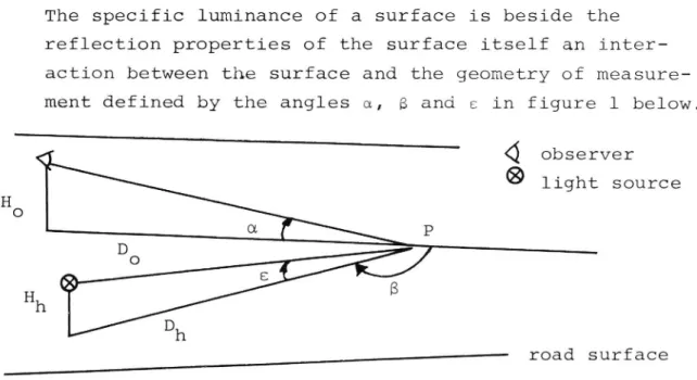
The specific luminance of a surface is beside the
reflection prOperties of the surface itself an inter
action between the surface and the geometry of measure ment defined by the angles a, B and e in figure 1 below.
Q
observer
69 light source
! - road surface
Figure 1 Geometric parameters of the specific luminance of a surface
Denotations in figure 1.: s = illumination angle
= observation angle
8 = azimuthal angle HO = observation heightHh = illumination height
D0 = distance of observation
Dh = distance of light source
P
= point of measurement
When the difference between the observation and
illumi-nation angles (a-e) is small and the azimuthal angle
(8) is about 1800 the specific luminance is often called
retroreflection. This concept, however, indicates that
the luminance is due to retroreflective elements of a
surface,v
x 1is not always the case. Therefore, the
more general concept of specific luminance is used.
Background
At present therejjsonly little knowledge about the
influence of the geometry of measurement when measur
ing specific lumiance of road markings. Since some
years measurements of specific luminance in Sweden have
been carried out with a portable instrument developed
and built by the National Swedish Road and Traffic
Research Institute (VTI). The regulations of the
Swedish Road Administration concerning road markings
(BYA 365:232) are based on measurements with the
Swedish instrument. But it is unknown whether the
geo-metry of measurement of this instrument is the most
valid one. Other measurement geometries would simulate
more realistic distances of road marking visibility in
night driving. On the other hand it is desirable that
the measurements have small random errors. This is a
growing problem in simulating larger and larger
distances of observation. Besides that, the instrument
should be light and handy.
COMPARATIVE MEASUREMENTS
Purpose of the study
The purpose of this study is to investigate how the
specific luminance, mainly regarding road markings,
varies with the instrument used. Three different
instru-ments have been compared by repeated measureinstru-ments of a
number of surfaces.
Description of the instruments
Three portable instruments for measurement of specific
luminance have been used. For all of them the azimuthal
angle 8 is 1800, i.e. the "observer", the light source
and the point of measurement are in the same vertical
plane. The "observer" is situated above the light
source. The measurement geometry of each instrument is defined in figure 2.
I
Q
observer
Q9 light source
, :IHh e
L
p
Figure 2
The measurement geometry of each instrument
8 = 1800. The denotations of the parameters
are presented in figure 1.
The following instruments have been compared:
l)
2)
3)
An instrument developed and built by the National
Swedish Road and Traffic Research Institute. This
instrument is denoted S and its measurement values
SL(S).
A commercial Swiss instrument, Erichsen Type RM 710. It is denoted CH and its measurement values
SL(CH).
An instrument developed and built by the Norwegian
Technical High School,
and SL(N)
Trondheim, Norway. Denoted N
respectively.
Specifications of the instruments are shown in table
1,
where measurement and aperture angles, simulated
distances and measurement areas are presented.
VTI REPORT NO.
Measurement
Aperture
Measure-
Simulated geome-.
geometry angles mentauxxi try on the road Instrument a s d/e wo wh A HO Da nl Hh
S
3.2
1.7
1.9
17
5x9
65x80
1.22
21.9
0.65
CH
5.0
3.5
1.4
8
8
100x100
0.93
10.6
0.65
N
1.37 0.74 1.9
20
20
200x65
1.20
50.3
0.65
Tab1e_l. Instrument specifications a measurement angle (degrees)
8
illumination angle (degrees)
mo
aperture angle of the measurement system (minutes)
wh aperture angle of the illumination system (minutes) A measurement area (1ength><width, mm)
HO
observer eye height above the road surface (m)
DO
simulated distance to the point of observation (m)
Dh simulated distance to the point of illumination (m)
Hh
headlight mounting
height above the road surface
(assumed value, m)
The simulated headlight mounting height (Hh=0,65 m),
has been chosen according to the car population in the
Scandinavian countries. Ho' Do and Dh were then
calcu-lated Ho tan a = E- (2) and o H
tan 8 = 52
(3)
hWhen DO=Dh the equations (2) and (3) give H _ h
Dh _ tan a
(4)
and _ tan aHo _ Hh
tan 8
(5)
When a and e are small:
~
3
HO
Hh E
(6)
The relation d/e is a significant parameter of the
Specific luminance of a surface (Morkertrafik 3, 1980).
This parameter is discussed in section 4.
The specifications of the instruments in table 1 mean
that the geometry of the N-instrument corresponds to
that which has been recommended for field measurements
by the Nordic Research COOperation for Night Traffic.
The geometry of the S-instrument is mainly based on
practical considerations. The CH instrument is based
on a German standard.
Surfaces of measurement
The specific luminance of three different types of surfaces has been measured: worn road markings, new road markings and road pavements. Simultaneous measure-ments with two or three instrumeasure-ments have mainly been
carried out as an extension of the evaluation program
of road markings in a larger project. All field
measure-ments were carried out in the summer of 1979. The
results are presented in the sections 3.2, 3.3 and 3.4
below.
There usually are large amounts of drOp on micro pearls
on the surface of new road markings. This means that
the specific luminance measured, mainly is a function
of these pearls. When the road marking is worn the
drop-on pearls have disappeared and the pre-mix
micro-pearls have appeared at the surface of the material.
The specific luminance value then derives from those
retroreflecting EM%n £5 and the road marking compound
itself. On road pavements there is no retroreflective
material. Therefore the specific luminance of
pave-ments strongly depends on the texture of the surface.
This study is mainly concerned with road markings.
RESULTS
Relation between instruments
The results are presented in tables 2 8. In each table
the relations betmmxnimeasurement values of two or all three of the instruments are calcultated. These
rela-tions (denoted X1, x2 and x3) are defined as follows.
_ SL(CH)
X1
SL(S)
(7)
_ SL(N)
SL(s)
_ SL(N)
Specific luminances
SL(CH)
(8)
of worn road markings
The specific luminance of worn road markings have been
measured at four different occasions.
presented in table 2-5 below.
The results are
Road marking
Specific luminance
Relation between
type
(cd/mz) lux
instruments
no. SL(S) n SL(CH) n X1
l
100
2
55
2
0.55
2
7O
2
54
2
0.77
3
67
2
54
2
0.81
4
144
2
79
2
0.55
5
116
2
62
2
0.53
6
103
2
66
2
0.64
12
12
22120.64
Table 2. Specific luminancesc fworn road markings I
Date
1979-06 15
Road E4 (after 1979 07-04 road no 636)
Place
Vikingstad (10 km from Linkoping)
Weather
cloudy, +l7OC
Instruments S, CH
Types of markings worn thermo plastics
Notes
VTI REPORT NO.
Each of six different compounds was
appli-cated as a tranversal line on the road.
The influence of this application on the
specific luminance is unknown.
n is the number of measurements.Table 3.
Relation
2 between
Specific luminance (Cd/m )lux instruments
Road mark 9 H 9
Road ing type Sample SL(S) 5(0) n SL(Cn) 5(0) n xl
E4 R 1 64 3.4 10 73 2.2 10 1.14 2 62 6.6 10 73 3.6 10 1.18 3 69 4.3 10 64 4.7 10 0.93 4 69 6.1 10 67 6.4 10 0.97 5 76 4.7 10 78 5.6 10 1.03 6 75 4.0 10 73 5.2 10 0.97
1-6 §E=69
60 SL=71
6O §1=1.03
OR 1 105 4.2 10 116 5.3 10 1.10 2 106 3.7 10 116 2.9 10 1.09 3 86 10.5 10 94 7.9 10 1.09 4 98 3.8 10 88 4.7 10 0.90 5 111 6.8 10 103 5.2 10 0.93 6 129 3.4 10 116 4.1 10 0.901 6 §E=106
60 §E=106
60 §l=1.00
RV58 R 1 69 10.1 10 77 3.9 10 1.12 2 75 11.1 10 74 11.8 10 0.99 3 84 9.5 10 81 5.7 10 0.96 4 47 20.0 10 46 11.7 10 0.98 5 81 13.0 10 82 10.6 10 1.01 6 98 13.2 10 101 9.9 10 1.031 6 §i=76
60 55:77
60 x1 1.01
OR 1 115 15.6 10 109 13.2 10 0.95 2 87 12.1 10 87 6.1 10 1.00 3 95 12.5 10 97 6.5 10 1.02 4 133 4.4 10 124 8.3 10 0.93 5 123 8.1 10 111 5.5 10 0.90 6 89 11.0 10 90 10.8 10 1.011-6 §f=107
60 §i=103
60 §l=o.96
Specific luminances of worn road markings II
Date
1979 06 18, resp. 1979-06 20
Road
E4, RV 58
Place
near Nykoping
O 0
Weather
overcast, +19 C resp. +21 C
Instruments S, CH
Types of markings Thermo-plastic material manu
factured by Cleanosol AB, Sweden.
VTTIIREPCHUP NO.
R is containing 20% and OR 30%
micro-pearls layed as an edge line
in 1977. Road 58 is a surface
dressing while E4 is an asphalt
concrete. n is the number of
measurements, s the standard
devia-tion in per cent of the mean value.
Specific luminance
RGlatiOD bEtween
2 instruments
(cd/m )lux
Measure-
Repeated
ment area measure- SL(S) SL(CH) SL(N) X1 X2 x3
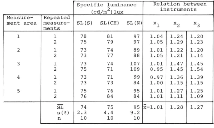
ments 1 1 78 81 97 1.04 1.24 1.20 2 75 79 97 1.05 1.29 1.23 2 l 73 74 89 1.01 1.22 1.20 2 73 77 88 1.05 1.21 1.14 3 1 73 74 107 1.01 1.471 1.45 2 75 71 109 0.95 1.45 1.54 4 l 73 71 99 0.97 1.36 1.39 2 73 73 84 1.00 1.15 1.15 5 l 75 76 95 1.01 1.27 1.25 2 76 84 84 1.01 1.11 1.09
§E
74
75
95 i=1.01
1.28
1.27
s( ) 2.3 4.4 9.2 n 10 10 10Table 4. Specific luminances of worn road markings III Date 1979-07-04
Road no. 636 (E4 before 1979-07-04) Place Vikingstad, 10 km from Linkoping
Weather
cloudy, +16OC
Instruments S, CH, N
Types of markings
Notes
VTI REPORT NO.
188A
Thermo plastic material with
15% pre-mix micro-pearls.
Manu-factured by Nordsjo Véglinje AB.
Edge line, about one year old.
Three measurement areas were
chosen on one marking and two
on another. Every area was then
measured twice with each
instru-ment. s is the standard deviation
lO
Road Specifig luminance Relation between marking Sample (cd/m )/1ux instruments
type SL(S) s(%) n SL(CH) s(%) n xl
A
l
133
8.9
10
93
8.6
10
0.70
2
139
8.8
10
92
9.6
10
0.66
B
l
161
5.0
10
116
8.0
10
0.72
2
197
10.9
10
137
9.6
10
0.70
C
1
176
9.8
10
132
10.5
10
0.75
2
167
5.0
10
128
4.6
10
0.77
60
60
i1 0.72
Table 5. Specific luminances of worn road markings IV
Date
1979-08-23, 1979-08-24
Road
Rv40
Place
Landvetter, near Gothenburg
Weather
Overcast, +16OC resp. cloudy +150C
Instruments S, CH
Types of markings
A: Hotline 2
15% pre-mix micro-pearls
B: Mercalin R3 20% pre-mix micro-pearls
C: OR-compound 30% pre mix micro pearls
Notes continuous edge line marking on a
motor-way. Each value is a mean of 10
measure-ments. 5 is the standard deviation in
per cent of the SL value.
Specific luminances of new road markings
The specific luminance of new road markings were
measured at two different occasions. The results are
presented in table 6 and 7 below.
ll
Date Road Place Weather Instruments
Type of marking
NotesVTI REPORT NO. 188A
1979-07-02
E4
Tift,
S, CH, N
Road markings on a motorway
"Hotline 2" manufactured by
Nordsjo Vaglinje AB. Drop-on
micro-pearls 30 kg/km.
Five measurement areas were chosen.
twice with each instrument. 8 is the standard deviation in
percentage of the SL value.
Each area was measured
Specific luminance Relation between
(cd/m2)/1ux
instruments
Road Measure- Repeated
marking ment area measure SL(S) SL(CH) SL(N) x1 x2 x3
ments Contin- 1 1 128 120 234 0.94 1.83 1.95 uous 2 128 120 219 0.94 1.71 1.83 edge marking 2 1 131 112 230 0.85 1.76 2.05 2 137 114 231 0.83 1.69 2.03 3 1 134 113 244 0.84 1.82 2.16 2 136 123 254 0.90 1.87 2.07 4 1 123 120 235 0.98 1.91 1.96 2 133 118 228 0.89 1.71 1.93 5 1 134 119 225 0.89 1.68 1.89 2 137 116 228 0.85 1.66 1.97
§i
132
118
233 E 0.89 1.77 1.97
s (%) 3.5 3.1 4.3 n 10 10 10 lane 1 1 87 110 178 1.26 2.05 1.62 marking 2 95 107 179 1.13 1.88 1.67 2 1 87 105 194 1.21 2.23 1.85 2 100 101 170 1.01 1.70 1.68 3 1 95 104 164 1.09 1.73 1.58 2 95 106 159 1.12 1.67 1.50 4 1 89 101 154 1.13 1.73 1.52 2 92 100 168 1.09 1.83 1.68 5 1 89 93 173 1.04 1.94 1.86 2 94 98 176 1.04 1.87 1.80§E
92
103
172 2 1.12 1.87 1.67
s(%) 4.6 4.8 6.6 n 10 10 10Table 6. Specific luminances of new road markings I
(open to the public 1979-07-04)
near Ligkoping
l2
Road
Specific luminance
Relation between
marking
Sample
(cd/m2)/lux
instruments
type
SL(S) s(%)
n SL(CH) s(%)
n
xl
R3
1
292
9.4
10
244
11.4
10
0.84
2
298
12.2
10
256
18 7
10
0.86
3
315
4.9
10
261
6.1
10
0.83
4
323
6.9
10
285
8.4
10
0.88
5
370
1.7
10
387
6.6
10
1.05
6
368
1.3
10
346
4.2
10
0.94
R4
1
365
1.3
10
340
10.1
10
0.93
70
70
El 0.91
Table 7. Specific luminances of new road markings II
Date
1979-08-23, 1979-08-24
Road RV40
Place Landvetter, near Gothenburg
Weather
overcast, +16OC resp.
cloudy, +150C Instruments S, CH
Types of markings Mercalin R3 and R4,
manufac-tured by Geveko Industri AB.
Unknown amount of drop-on
micro-pearls. Each SL value is the mean of 10 measurements. 3 is the standard deviation in
per cent of the SL-value.
.4
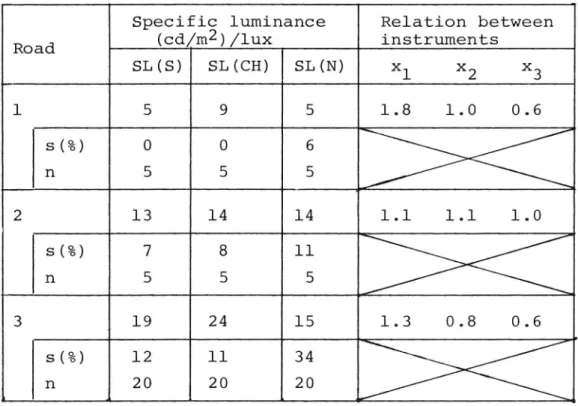
Specific luminances of road pavements
Measurements have been carried out on three different
types of road pavements at one occasion. are shown in table 8.
VTI REPORT NO.
188A
l3
Specifig luminance Relation between
Road
(Cd/m )/lux
instruments
SL(S)
SL(CH)
SL(N)
x1
x2
x3
1
5
9
5
1.8
l 0
0.6
s(%)
n
2
l3
l4
l4
1 l
l l
1.0
s(%)
ll
n
5
3
19
24
15
1.3
O 8
0.6
s(%)
12
ll
34
n
20
20
20
Table 8. Specific luminances of road pavements
Date
1979 07-02, 1979-07-04
Road
l:E4 (open to public 1979-07-04)
2:E4 (before 1979-07-04)
3:ll36
Place
lzTift, near Linkoping
2:Vikingstad, near Linkoping 3:Berg, near Linkoping
Instruments S, CH, N
VTI REPORT NO.
Typesc fpavements
Notes
188A
l:New black asphalt concrete
2:Worn asphalt concrete
3:Surface dressing
Each SL value is the mean value of n measurements. 5 is the
stan-gard deviation in per cent of
SL.
14
Summary of relations between instruments
A summary of relations between instruments from tables
2-8 is presented in table 9 below.
Relation between instruments Old road markings
x1 x2 x3 Table 2 x1 0.64 Table 3
£1
1.00
Table 4i
1.01
1.28
1.27
Table 5El
0.74
New road markings
Table 6
§
1.12
1.87
1.67
Table 7 0.91 -
-x 1 Road pavements
Table 8
New black asphalt
1.8
1.0
0.6
Worn asphalt
1.1
1.1
1.0
Surface dressing 1.3 0.8 0.6
Table 9. Summary of relations between instruments from tables 2-8
15
Comments on the results
From tables 2-8 it is evident that the relations between
instruments (xl, x2 and x3)
worn road markings, for example, x
vary in a high degree. On 1 assumes values from 0.53 to 1.18. The description of the relation between measurements of different instruments seems to be a difficult task.
However, looking at only one measurement occasion on one single type of road marking on one single type of road surface, x1, x2 and x3 are much more consistent.
This fact indicates that the measurement value could
be influenced by different factors i.e. texture of the
measurement area, amount of retroreflective material, degree of wear, type of material, weather conditions, etc. This variation will be discussed further in
sec-tion 4.
From tables 4 and 6 can be seen that the standard deviation of the measurement values (per cent) is larger for the N instrument especially when measuring worn road markings. One reason for this can be that the random error tends to increase with decreasing angles of illumination and observation.
DISCUSSION
Relations between instruments
In this section specific luminance measurements of road markings are discussed.
Obviously, no simple relations exist between measure
ment values of the three instruments. The relations
between instruments x1, x2 and x3 have varied with
l6
measurement occasion and object. The ideal result would be constant relations between instruments (x1, x
x3). In that case it would be easy
ment values from one instrument to
Some tentative explanations to why ween instruments x1, x and x
2 and
to translate measure another.
the relations
bet-are variables and not
2
3
constants will be discussed below:
.1
VTI REPORT
Dependence of d-s
The difference between the angles of observation
and illumination (d a) is important when measuring
retroreflective materials. The micro-pearls in road
markings tend to reflect the incident light back in
the direction of illumination. That is to say, the
specific luminance will increase with decreasing
differences between the illumination and observa The angle between illumination
tion angle (d-s).
and observation (d-s) of the S- and CH instruments is 1.50, compared to 0.630 of the N instrument. This factor would then rank the measurement values of the instruments in the following order SL(S) = = SL(CH)<SL(N).
Dependence of a
Assume that a certain road marking consists of 30% pre-mix micro-pearls and that the tops of the
pearls are rising above the surface. When measur-ing the luminance of the surface in an observation angle of u=90O the surface will contain 30% retro-If, the observation reflective material. however,
angle decreases, the apparent surface covered with
retroreflective material will increase. It is not known if this effect is significant within small angles (a<50), but if it is, the measurement
between the instruments would tend to rank SL(CH)<SL(S)<SL(N).
values
in the following order:
l7
.3
Dependence of d/s
S¢rensen has noticed (Morkertrafik nr 3, 1980) that
the specific luminance of road pavements tends to
depend on the relation d/s. This relation is also
important when measuring specific luminance of
road markings with or without retroreflective
materials. Lundkvist and S¢rensen (1980) have shown that the specific luminance decreases with an
increasing relation d/s (d> ). This effect is
related to that mentioned under .1 but it is also
valid for non retroreflective materials. According to the specifications of the instruments in table
1 this factor would then rank the measurement
values of the instruments in the following order:
SL(S)~SL(N)<SL(CH).
.4
Dependence of l/ -l/d
The surface of a road marking, highly magnified, is shown in figure 3 below. The surface is not perfectly smooth, but contains a lot of very small peaks. Only one such peak is shown in figure 3.
8
angle of illumination
l, /
0L
angle of observation
2 /
//
1/
z
/'
.
/'
/,
:
7
d-a
z (0 7
__ _..4'.h
a 51_
Ix
Figure 3
Schematic View of a highly magnified road
marking surface illuminated by vehicle
headlights.
18
Behind the peak there is a shadowed, unilluminated
area of length l (with undefined width). This
shadowed area can partly be seen and measured from
the direction of observation. This visible but not
illuminated area has the length a. The length of l and b = l-a are specified below.
_ h
l
tan a
(10)
p h
and b = m
From (10) and (11) follow:
1
1
a : l-b : h(tan s - tan a)Zh(1/ - 1/d) (12) whencxand.eare small and in radians. Partial
derivation of (12) gives:
6a = E2<<O for any e:::>a decreases With increaSing eh . . .
g: 32:>O for any a::::> a decreases with decreasing a where a is the unilluminated part of the road which
is measured.
This factor indicates that the specific luminance
of a road surface will increase with increasing 8 and decreasing a (when d2> ). Inserting measurement angles of the three instruments in equation (12) will give the following result.
a(S) = 15.8 h a(CH) = 4.9 h a(N) = 35.6 h
19
The results show the relative amount of shadowed
area measured by the three instruments.
This factor would then rank the specific luminances of the instruments in the following order:
SL(N)<SL(S)<SL(CH).
.5 Dependence of wO-wh
If the aperture angle of the measurement system is larger t mui that of the illuminating system it will have the same effect on the specific luminance value as an incrase in the angle a (see .4 above) that is to say measurements of too large non illumi nated areas. With reference to the specifications
of the instruments in table 1 this factor would
rank the measurement values in the following order:
SL(S)<SL(N) = SL(CH).
.6 Dependence of $0 and uh in relation to a and e As mentioned under .1 the specific luminance of retroreflective materials is to a high degree dependent on the angle (d-e).
w
aperture of
obser-8 angle of illumination
Vatlon System
a angle of observation
wh aperture of illumi
nation system
Figure 4
Apertures of observation and illumination
systems.
20
According to figure 4 the angle of the incident
light vary between eiwh/Z and that of the measured
light between aiwo/Z. When the difference d-e
decreases an increasing systematic error is intro-duced if not the aperture angles are decreased in the same degree.
The influence on the relation between instruments
(xl, x2 and x3) of the factors l-6 above are
pre-sented in table 9 below.
'Factors of geometry influencing Relation between
measurements of specific
instruments
1 -'uminance (S )L I x1 x2 x3 1. a-e 21 >1 >1 2. a <1 >1 >1
3. d/e
>1
3
<1
4. l/ -l/d
>l
<1
<1
5. wO-wh >1 >1 :1 6. $0, wh in relation to a, 8 <1 >l >l Table 9. Factors of geometry influencing measurementsof specific. luminance.
Numbers on the left
refer to paragraphs in the discussion above. Observe that the strength of different effects on the SL-value is unknown.
A dirty road marking or one in which the micro-pearls have been damaged would reflect light more
like ordinary road-pavements, i.e. effects from
.1, .2 and .6 would be neglectable.
If the micro-pearls have been pushed down into the
compound of the road marking (soft compounds) they
would be invisible because of small angles of
illu-mination. This means that an instrument with a
large angle of illumination would show higher
spe-cific luminance then one with a smaller a.
21
Laboratory measurements
Results from laboratory measurements on new road
mark-ings are schematically shown in figure 5.
O SL(S)
SL
A
/\ SL(CH) D SL(N) SL(CH) -SL(N) SL(S)11
22
50
m
Figure 5. Results of SL-measurements in the laboratory. Hh = 0.65 m and D0 = Dh. Simulated distances HO and Dh.
Figure 5 indicates that SL(N)3SL(S)<SL(CH), (i.e. xl>l; x2=l; x3<l). This relation between instruments predicted
from the laboratory measurements does not correspond
well to the relations found in the field measurements.
Sources of error
This study shows
that the specific luminance value
received from one instrument cannot be translated to
thatc fanother instrument of different geometry. Would
the measurement values then have been identical in the
case the instruments had had the same measurement geo-metry? The bad correspondance between laboratory and
field measurements indicates that there also can be
large systematic errors. In order to solve this problem
it is necessary to compare measurements of each
instru-ment by independent measureinstru-ments of identical geometry
in the laboratory.
22
CONCLUSIONS
Specific luminance measured with instruments not having
an identical geometry of measurement and/or aperture
angles cannot be compared. This is valid for new and
worn road markings as well as for road pavements.
Translating the measurement values of one instrument to another with different geometry and/or aperture angles is a very complex task. Making a good
instru-ment for measureinstru-ments of specific luminance will be a
balancing Un c between observation, illumination and
aperture angles in order to recieve reliable SL values
which on the same time can be related to the drivers
visibility of road markings and road pavements.
23
REFERENCES
Morkertrafik nr 2 (1978). Light reflection properties
of road surfaces. Nordic Research COOperation for
Night Traffic.
Morkertrafik nr 3 (1980). Lighting and visual conditions
on rural roads. Section 3.2. Light reflection
proper-ties of road surfaces. Nordic Research Cooperation
for Night Traffic. (in press)