Quality Assurance for Dependable
Embedded Systems
Andreas Johnsen A n d re a s J ohn se n Q U A LIT Y A SS U R A N C E F O R D EP EN D A B LE E M B ED D ED S YS TE M S 2018 ISBN 978-91-7485-372-8 ISSN 1651-4238Address: P.O. Box 883, SE-721 23 Västerås. Sweden Address: P.O. Box 325, SE-631 05 Eskilstuna. Sweden E-mail: info@mdh.se Web: www.mdh.se
The main goal of this doctoral thesis is to improve verification processes of dependable embedded systems. An embedded system is a computer system that has a dedicated function within a larger electrical and possibly mechanical system. A dependable embedded system is a computer system that is critical to the system it is embedded within. Examples of dependable embedded systems are electronic control systems in airplanes, trains and cars, such as an autopilot. Since an incorrect operation of these systems may endanger people and the environment, it is crucial to verify that the systems achieve high quality before they are put into service. In this regard, verification means efforts that intend to detect and correct defects in the systems that are being developed. Verification of embedded systems commonly involves manual work, which is becoming increasingly labor intensive and error prone due to the increasing complexity of the systems. The contribution of this doctoral thesis is a framework of verification techniques that provides an automated verification process to reduce the cost of human labor and the risk of human error. A comprehensive set of verification techniques is included in the framework so that defects are detected throughout the development process, in-cluding early design faults, intermediate implementation faults and later maintenance faults. In addition, the framework is based on a mathematical foundation to ensure reliable verification results. Altogether, the framework provides a significant protection against costly and hazardous defects that may arise in the development of dependable embedded systems.
The performance of the verification framework is evaluated in this thesis by means of case studies, where, for example, it is applied to a safety-critical train control system. The results of the studies demonstrate a high fault detection rate and a scalability to advanced embedded systems with multi-core processors and multi-tasking.
QUALITY ASSURANCE FOR DEPENDABLE EMBEDDED SYSTEMS
Andreas Johnsen
2018
ISSN 1651-4238
QUALITY ASSURANCE FOR DEPENDABLE EMBEDDED SYSTEMS
Andreas Johnsen
Akademisk avhandling
som för avläggande av teknologie doktorsexamen i datavetenskap vid Akademin för innovation, design och teknik kommer att offentligen försvaras fredagen den 26 januari 2018, 13.00 i Gamma, Mälardalens högskola, Västerås.
Fakultetsopponent: Professor Paola Inverardi, University of L'Aquila
Architectural engineering of embedded computer systems comprehensively affects both the development processes and the abilities of the systems. Rigorous and holistic verification of architectural engineering is consequently essential in the development of safety-critical and mission-critical embedded systems, such as computer systems within aviation, automotive, and railway transportation, where even minor architectural defects may cause substantial cost and devastating harm. The increasing complexity of embedded systems renders this challenge unmanageable without the support of automated methods of verification, to reduce the cost of labor and the risk of human error.
The contribution of this thesis is an Architecture Quality Assurance Framework (AQAF) and a corresponding tool support, the Architecture Quality Assurance Tool (AQAT). AQAF provides a rigorous, holistic, and automated solution to the verification of critical embedded systems architectural engineering, from requirements analysis and design to implementation and maintenance. A rigorous and automated verification across the development process is achieved through the adaption and integration of formal methods to architectural engineering. The framework includes an architectural model checking technique for the detection of design faults, an architectural model-based test suite generation technique for the detection of implementation faults, and an architectural selective regression verification technique for an efficient detection of faults introduced by maintenance modifications. An integrated solution provides traceability and coherency between the verification processes and the different artifacts under analysis, which is essential for obtaining reliable results, for meeting certification provisions, and for performing impact analyses of maintenance modifications. The Architecture Quality Assurance Tool (AQAT) implements the theory of AQAF and enables an effortless adoption into industrial practices. Empirical results from an industrial study present a high fault detection rate at both the design level and the implementation level as well as an efficient selective regression verification process. Furthermore, the results of a scalability evaluation show that the solution is scalable to complex many-core embedded systems with multithreading.
ISBN 978-91-7485-372-8 ISSN 1651-4238
Architectural engineering of embedded computer systems comprehensively af-fects both the development processes and the abilities of the systems. Rigorous and holistic verification of architectural engineering is therefore essential in the development of safety-critical and mission-critical embedded systems, such as computer systems within aviation, automotive and railway transportation, where even minor architectural defects may cause substantial cost and dev-astating harm. The increasing complexity of embedded systems renders this challenge unmanageable without the support of automated methods of verifi-cation, to reduce the cost of labor and the risk of human error.
The contribution of this thesis is an Architecture Quality Assurance Frame-work (AQAF) and a corresponding tool support, the Architecture Quality As-surance Tool (AQAT). AQAF provides a rigorous, holistic and automated so-lution to the verification of architectural engineering of critical embedded sys-tems, from requirements analysis and design to implementation and mainte-nance. A rigorous and automated verification across the development process is achieved through the adaption and integration of formal methods to archi-tectural engineering. The framework includes an archiarchi-tectural model checking technique for the detection of design faults; an architectural model-based test suite generation technique for the detection of implementation faults; and an architectural selective regression verification technique for an efficient detec-tion of faults introduced by maintenance modificadetec-tions.
An integrated solution provides traceability and coherency between the ver-ification processes and the different artifacts under analysis, which is essen-tial for obtaining reliable results; for meeting certification provisions; and for performing impact analyses of maintenance modifications. The Architecture Quality Assurance Tool (AQAT) implements the theory of AQAF and enables an effortless adoption into industrial practices. Empirical results from an in-dustrial study present a high fault detection rate at both the design level and the
implementation level, as well as an efficient selective regression verification process. Furthermore, the results of a scalability evaluation show that the solu-tion is scalable to complex multi-core embedded systems with multi-tasking.
Summary
Denna doktorsavhandling handlar huvudsakligen om att f¨orb¨attra verifierings-processer av tillf¨orlitliga inbyggda system. Ett inbyggt system ¨ar ett datorsys-tem som har en specifik funktion inom ett st¨orre elektroniskt och m¨ojligtvis mekaniskt system. I motsats till inbyggda system finns exempelvis personda-torer, som ¨ar utvecklade f¨or ett stort antal olika anv¨andningsomr˚aden. Ett tillf¨orlitligt inbyggt system ¨ar ett datorsystem vars funktion ¨aven ¨ar kritiskt f¨or systemet det ¨ar inbyggt i och dess omgivning. Exempel p˚a tillf¨orlitliga inbyggda system ¨ar elektroniska styrsystem i flygplan, t˚ag, och bilar, s˚a som bilens farth˚allare. Eftersom en felaktig funktion av dessa system kan leda till fara f¨or m¨anniskor och omgivningen, ¨ar det avg¨orande att verifiera att systemen uppn˚ar en h¨og kvalitet innan de distribueras och tas i bruk. Verifiering betyder i detta avseende medel som har f¨or avsikt att uppt¨acka och korrigera defekter i systemet som utvecklas.
Verifiering av inbyggda system ¨ar en st¨andigt v¨axande utmaning som
grun-dar sig i den ¨okande komplexiteten av systemen. ˚A andra sidan g¨or den
avancer-ade tekniken det m¨ojligt att exempelvis utveckla effektiva transportmedel, s˚a som autonoma elbilar. N¨ar komplexiteten ¨okar m˚aste systemarkitekter g¨ora allt mer komplicerade beslut g¨allande val av arkitekturdesign. En arkitektur-design ¨ar en ¨overgripande teoretisk beskrivning av det system man planerar att utveckla. I beskrivningen ing˚ar de v¨asentliga komponenterna, s˚a som sen-sorer, processen-sorer, st¨alldon, datorminnen, databussar, och applikationer, hur de skall vara strukturerade, och hur de skall interagera med varandra och med om-givningen systemet skall agera i. Med h¨ansyn till tillf¨orlitliga system ¨ar arkitek-turdesignen av exceptionell betydelse i den meningen att graden av tillf¨orlitlig-het till stora delar best¨ams av systemets struktur. Tillexempel inneh˚aller
gelektroniska system (avionik) ofta parallella datorer som utf¨or en och samma uppgift, s˚a kallad redundans. Om den prim¨ara datorn fallerar kan systemet ¨overg˚a till den sekund¨ara och p˚a s˚a s¨att bibeh˚alla sin funktion och en s¨aker fly-gning trots uppkomsten av ett allvarligt fel. Denna specifikation ¨over arkitek-turdesignen anv¨ands sedan som underlag f¨or den resterande utvecklingspro-cessen, med intentionen att implementera ett system enligt specifikationen. Eftersom valet av arkitekturdesign best¨ammer ¨overgripande systemegenskaper och har l˚angtg˚aende p˚averkningar p˚a utvecklingsprocessen kommer ett felak-tigt beslut sannolikt resultera i ett system som inte uppn˚ar kvalitetskraven, kostsamma korrigeringar, och i v¨arsta fall personskador till f¨oljd av olyckor. S˚aledes ¨ar det n¨odv¨andigt att i st¨orsta m¨ojliga m˚an f¨orhindra och uppt¨acka fe-laktiga beslut g¨allande systemets arkitekturdesign.
Tidigare har systemarkitekter beskrivit och analyserat arkitekturer manuellt. Detta ¨ar b˚ade tidskr¨avande och leder l¨att till misstag p˚a grund av den m¨anskliga faktorn. Den ¨okande komplexiteten blir d¨arf¨or om¨ojlig att hantera p˚a detta s¨att. P˚a senare ˚ar har datoriserade modelleringsspr˚ak utvecklats f¨or att hj¨alpa sys-temarkitekter att beskriva, simulera, och analysera en arkitekturdesign p˚a ett hanterbart och standardiserat s¨att. En datoriserad modell g¨or det ¨aven m¨ojligt att anv¨anda dagens kraftfulla datorer till att automatiskt utf¨ora analyser och verifieringar av designen. Ett annat problem ¨ar att en korrekt modell inte n¨odv¨andigtvis leder till en korrekt implementering (realisering) av modellen. Ett tillf¨orlitligt inbyggt system utvecklas ofta inom en komplicerad
organi-sation med ett stort antal ingenj¨orer med olikartade arbetsuppgifter. Aven¨
om modellen beskriver arkitekturdesignen p˚a ett standardiserat s¨att kan den m¨anskliga faktorn leda till att det implementerade systemet avviker fr˚an mod-ellen och f˚ar oacceptabla egenskaper. P˚a grund av detta ¨ar det ¨aven n¨odv¨andigt att analysera huruvida det implementerade systemets egenskaper ¨overensst¨am-mer med f¨orv¨antningarna. F¨or att analysera detta beh¨over man experimentera med implementationen. Denna typ av verifiering ben¨amns som “testning”. Om modellen ¨ar datoriserad kan testning av implementationen gentemot modellen utf¨oras automatiskt. Detta ¨ar ytterligare ett starkt sk¨al till att anv¨anda da-toriserade modelleringsspr˚ak, eftersom manuell testning ¨ar tidskr¨avande och, ˚aterigen, l¨att kan leda till misstag p˚a grund av den m¨anskliga faktorn. Slut-ligen f¨orekommer det ¨aven uppdateringar av inbyggda system som redan har genomg˚att verifiering. Eftersom uppdateringar kan introducera nya fel m˚aste systemet omverifieras, en s˚a kallad “regressionsverifiering”. Om uppdaterin-gen endast p˚averkar vissa delar av systemet ¨ar det ineffektivt att exekvera en fullst¨andig omverifieringsprocess, som ofta ¨ar resurskr¨avande f¨or komplexa system ¨aven om den ¨ar automatiserad. Att p˚a f¨orhand med s¨akerhet fastst¨alla
vilka delar av systemet som inte p˚averkas av en uppdatering och inte beh¨over ing˚a i omverifieringen ¨ar d¨aremot en komplicerad uppgift. En f¨or¨andring kan medf¨ora b˚ade direkta och indirekta p˚averkningar, vilket g¨or dem sv˚ara att anal-ysera med precision. Denna typ av omverifiering, d¨ar analyser utf¨ors f¨or att selektivt exekvera omverifieringsprocessen och p˚a s˚a s¨att undg˚a on¨odv¨andiga omverifieringar, ben¨amns som selektiv regressionsverifiering. En selektiv re-gressionverifieringsteknik ¨ar resurseffektiv s˚a l¨ange tidskostnaden f¨or analysen av uppdateringens p˚averkningar inte ¨overstiger tidsvinsten av att reducera om-fattningen av omverifieringsprocessen.
Bidraget av denna doktorsavhandling ¨ar en applikationsprogramvara, en s˚a kallad “app”, som automatiskt och rigor¨ost utf¨or verifieringar av arkitek-turmodeller, modell-baserad testning av implementationer, samt selektiv re-gressionsverifiering av arkitekturella uppdateringar. Detta ger ett helhetligt skydd mot kostsamma och riskfyllda fel som uppst˚ar i utvecklingsprocesser av tillf¨orlitliga inbyggda system. F¨or att uppn˚a p˚alitlighet har verktyget utveck-lats med hj¨alp av formella verifieringsmetoder, vilka bygger p˚a matematiska modeller och analyser.
Applikationsprogramvaran evalueras i denna avhandling genom en indus-triell fallstudie, vari verktyget till¨ampas p˚a ett s¨akerhetskritiskt inbyggt system. F¨or att uppn˚a statistiskt signifikanta resultat och inkluderande av de olika fel-typerna som potentiellt kan f¨orekomma i en utvecklingsprocess, baseras stu-dien p˚a en felinjiceringsmetodik, vari ett stort antal defekter avsiktligt inf¨ors i systemet f¨or att d¨arefter unders¨oka om verktyget uppt¨acker dem. Resultatet av studien visar p˚a en effektiv detektering av systemfel och en effektiv resur-sanv¨andning vid regressionsverifieringar. Ut¨over detta evalueras ¨aven verk-tygets skalbarhet i en studie best˚aende av ett flertal olikartade inbyggda system, vad g¨aller b˚ade typ och komplexitet. Studien visar att verktyget ¨ar kapabelt till att verifiera komplexa datorsystem med multiprocessorer (“multi-core proces-sors”) s˚a v¨al som multik¨orning av processer (“multi-tasking”).
I would first of all like to express my deepest gratitude to my advisors, Prof. Kristina Lundqvist, Prof. Paul Pettersson and Dr. Kaj H¨anninen, for their support, encouragement and guidance throughout my research. It has been nothing but a great pleasure to work with all of you.
There are so many other people to thank. I would like to jointly thank all the people at the IDT department, M¨alardalen University. Many special thanks to: Prof. Lars Asplund who encouraged me to become a Ph.D. student; my office-mates over the years, Jiale Zhou, Abhilash Thekkilakattil, H¨useyin Aysan, Adnan Causevic and Etienne Borde, for all the help and great office hours; Mehrdad Saadatmand, Federico Ciccozzi, Antonio Cicchetti and Thomas Lev-eque for all the fun that we have had both at work as well as outside of work; and professors Hans Hansson, Mikael Sj¨odin, Thomas Nolte, Cristina Sece-leanu, Sasikumar Punnekkat, Ivica Crnkovic and Jan Carlson, for the valuable knowledge and feedback I have received over the years.
I would also like to thank Radu Dobrin, Daniel Sundmark, Frank L¨uders, Andreas Gustavsson, Jan Gustafsson, Bj¨orn Lisper, Henrik Thane, Fredrik Ek-strand, H˚akan Forsberg, Kristina Forsberg, Alfonso Pierantonio, Omar Jaradat,
Mikael ˚Asberg, Aida Causevic, Leo Hatvani, Juraj Feljan, Aneta Vulgarakis,
Moris Behnam, Saad Mubeen, Dag Nystr¨om, S`everine Sentilles, Damir Iso-vic, Mikael Ekstr¨om, Nikola PetroIso-vic, Stephan Baumgart, Iain Bate, Yue Lu, Husni Khanfar, Guillermo Rodriguez-Navas, et al., for all the help, inspiration and interesting discussions. I thank the administrative staff, Jenny H¨agglund, Malin Rosqvist, Carola Ryttersson, Sofia J¨aderen, Gunnar Widforss, Susanne Fronn˚a, et al., for making many things easier.
Finally, I would like to express my deepest gratitude to my beloved family. My dear son, Carl-Axel, I hope you one day will read this. You are always in my thoughts, forever in my heart.
Papers Included in the Thesis
1Paper A An Architecture-based Verification Technique for AADL Specifi-cations; Andreas Johnsen, Paul Pettersson, and Kristina Lundqvist; In proceedings of the 5th European Conference on Software Architecture (ECSA), Essen, Germany, 2011.
Paper B Automated Verification of AADL-Specifications Using UPPAAL; Andreas Johnsen, Kristina Lundqvist, Paul Pettersson, and Omar Jara-dat; In proceedings of the 14th IEEE International Symposium on High Assurance Systems Engineering (HASE), Omaha, NE, USA, 2012. Paper C Regression Verification of AADL Models through Slicing of System
Dependence Graphs; Andreas Johnsen, Kristina Lundqvist, Paul Petters-son, and Kaj H¨anninen; In proceedings of the tenth International ACM Sigsoft Conference on the Quality of Software Architectures (QoSA), Lille, France, 2014.
Paper D AQAF: an Architecture Quality Assurance Framework for systems modeled in AADL; Andreas Johnsen, Kristina Lundqvist, Kaj H¨anninen, Paul Pettersson, and Martin Torelm; In proceedings of the 12th Interna-tional ACM Sigsoft Conference on the Quality of Software Architectures (QoSA), Venice, Italy, 2016.
Paper E AQAT: The Architecture Quality Assurance Tool for Critical Embed-ded Systems; Andreas Johnsen, Kristina Lundqvist, Paul Pettersson, and Kaj H¨anninen; In proceedings of the 28th International Symposium on Software Reliability Engineering (ISSRE), Toulouse, France, 2017.
1The included papers have been reformatted to comply with the thesis layout.
Paper F Experience Report: Evaluating Fault Detection Effectiveness and Re-source Efficiency of the Architecture Quality Assurance Framework and Tool; Andreas Johnsen, Kristina Lundqvist, Paul Pettersson, Kaj H¨annin-en, and Martin Torelm; In proceedings of the 28th International Sympo-sium on Software Reliability Engineering (ISSRE), Toulouse, France, 2017.
Related Papers
• Risk-based Decision-making Fallacies: Why Present Functional Safety Standards Are Not Enough; Andreas Johnsen, Gordana Dodig-Crnkovic, Kristina Lundqvist, Kaj H¨anninen, and Paul Pettersson; In proceedings of the 2nd International Workshop on decision Making in Software AR-CHitecture (MARCH), Gothenburg, Sweden, 2017.
• Industrial Experiences of Building a Safety Case in Compliance with ISO 26262; Raghad Dardar , Barbara Gallina, Andreas Johnsen, Kristina Lundqvist, and Mattias Nyberg; In proceedings of the 2nd Workshop on Software Certification (WoSoCER), Dallas, TX, USA, 2012.
• Formal Execution Semantics for Asynchronous Constructs of AADL; Jiale Zhou, Andreas Johnsen, and Kristina Lundqvist; In proceedings of the 5th International Workshop on Model Based Architecting and Con-struction of Embedded Systems, Innsbruck, Austria, 2012.
• Liability for Software in Safety-Critical Mechatronic Systems: An In-dustrial Questionnaire; Holger Kienle, Daniel Sundmark, Kristina Lund-qvist, and Andreas Johnsen; In proceedings of the 2nd International Workshop on Software Engineering for Embedded Systems (SEES), Zur-ich, Switzerland, 2012.
• Developing Dependable Software-Intensive Systems: AADL vs. EAST-ADL; Andreas Johnsen and Kristina Lundqvist; In proceedings of the 16th Ada-Europe International Conference on Reliable Software Tech-nologies, Edinburgh, UK, 2011.
Licentiate Thesis
• Architecture-based Verification of Dependable Embedded Systems; An-dreas Johnsen; M¨alardalen University, V¨aster˚as, Sweden, 2013.
I
Thesis
1
1 Introduction 3
1.1 Overview of Research Area . . . 3
1.2 Problem Formulation and Motivation . . . 6
1.3 Contribution to Research Area . . . 9
1.4 Outline . . . 11
2 Background Information 13 2.1 The Architecture Analysis and Design Language . . . 13
2.1.1 Sensor-To-Actuator AADL Example . . . 17
2.2 Control and Data Flow Analysis . . . 23
2.3 Model Checking . . . 26
2.3.1 Modeling . . . 26
2.3.2 Requirements Specification and Verification . . . 28
2.4 Model-based Testing . . . 32
2.5 Regression Verification . . . 35
2.6 Program Slicing . . . 35
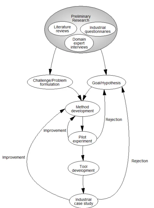
3 Research Methodology 39 3.1 Research Method . . . 39
3.2 Research Challenges and Goals . . . 41
4 Related Work 45 4.1 Verification Criteria . . . 45 4.2 Formal Verification . . . 46 4.3 Model-based Testing . . . 47 4.4 Regression Verification . . . 48 xi
4.5 Verification Framework . . . 49
4.6 Hazard Analysis . . . 50
5 Summary of Contributions 53 5.1 Architecture Flow Graphs . . . 55
5.2 Verification Criteria . . . 58
5.2.1 Extension of Paper A: Inclusion of Data Flow Sources and Data Flow Sinks . . . 59
5.3 Formal Semantics . . . 60
5.3.1 Extension of Paper B: Inclusion of Shared Resources . 62 5.4 Model Checking with Observer Automata . . . 69
5.5 Model-based Testing with Observer Automata . . . 70
5.6 Selective Regression Verification . . . 70
5.6.1 Extension of Paper D: Dynamic Dependence Analysis 72 5.7 The Architecture Quality Assurance Tool . . . 75
6 Evaluation 87 6.1 Utility . . . 87 6.1.1 Design of Study . . . 87 6.1.2 Results . . . 89 6.1.3 Discussion . . . 92 6.2 Scalability . . . 92 6.2.1 Design of Study . . . 93 6.2.2 Results . . . 95 6.2.3 Discussion . . . 105
7 Limitations And Future Work 107 8 Conclusion 111 Bibliography 113
II
Included Papers
123
9 Paper A An Architecture-based Verification Technique for AADL Specifi-cations 125 9.1 Introduction . . . 1279.3 The Architecture-based Verification Technique . . . 128
9.4 AADL Verification Criteria . . . 130
9.4.1 Verification objectives . . . 130
9.4.2 Verification Criteria . . . 132
9.5 Conclusion . . . 135
Bibliography . . . 137
10 Paper B Automated Verification of AADL-Specifications Using UPPAAL 139 10.1 Introduction . . . 141
10.2 AADL and The Verification Technique . . . 142
10.3 Transformation to Timed Automata . . . 146
10.3.1 Transformation Rules . . . 148 10.4 Case study . . . 155 10.5 Related Work . . . 158 10.6 Conclusion . . . 158 Bibliography . . . 159 11 Paper C Regression Verification of AADL Models through Slicing of System Dependence Graphs 161 11.1 Introduction . . . 163
11.2 Background . . . 165
11.3 Preliminaries . . . 165
11.4 Slicing through system dependence graphs . . . 170
11.4.1 Generating Control Flow Graphs . . . 172
11.4.2 Generating Program Dependence Graphs . . . 178
11.4.3 Generating the System Dependence Graph . . . 180
11.5 Slicing and Selection . . . 185
11.6 Conclusions . . . 186
Bibliography . . . 187
12 Paper D AQAF: an Architecture Quality Assurance Framework for systems modeled in AADL 189 12.1 Introduction . . . 191
12.2 Line Trip Relay Interface and Supervision . . . 193
12.3 Architecture Flow Graphs . . . 196
12.4 Verification Criteria and Sequences . . . 201
12.5 Formal Semantics in Timed Automata . . . 203
12.6 Observers Generation and Model Checking . . . 205
12.7 Model-based Testing . . . 208
12.8 Selective Regression Verification . . . 209
12.9 Validation . . . 211
12.10Related Work . . . 214
12.11Conclusion . . . 215
Bibliography . . . 217
13 Paper E AQAT: The Architecture Quality Assurance Tool for Critical Em-bedded Systems 219 13.1 Introduction . . . 221
13.2 AQAT Front-end and Usage . . . 222
13.2.1 Use Cases . . . 222
13.2.2 User Interface . . . 225
13.3 AQAT Back-End . . . 231
13.3.1 Architecture Analysis and Design Language . . . 231
13.3.2 Architecture Flow Graphs . . . 234
13.3.3 Verification Criteria and Verification Sequences . . . . 237
13.3.4 Transformation To Timed Automata . . . 238
13.3.5 Model Checking . . . 240
13.3.6 Test Suite Generation . . . 242
13.3.7 Selective Regression Verification . . . 243
13.4 Evaluation . . . 245
13.5 Related Work . . . 246
13.6 Conclusion and Future Work . . . 247
Bibliography . . . 249
14 Paper F Experience Report: Evaluating Fault Detection Effectiveness and Resource Efficiency of the Architecture Quality Assurance Frame-work and Tool 253 14.1 Introduction . . . 255
14.2 The Architecture Quality Assurance Framework . . . 256
14.3 Case Study Design . . . 259
14.3.1 Objectives of Study . . . 259
14.3.3 The Case Study Subject . . . 260
14.3.4 Case Study Method and Expected Results . . . 262
14.3.5 Fault Types and Fault Injections . . . 265
14.3.6 Case Study Instrumentation . . . 266
14.4 Results . . . 268
14.5 Discussion . . . 276
14.6 Related work . . . 278
14.7 Conclusion and Future Work . . . 279
Thesis
Introduction
1.1
Overview of Research Area
Digital technology is an integral part of societies and often used in applications where the welfare and the safety of humans and environments are dependent on it [1]. For example, computer systems are embedded in control systems of nuclear power plants, public transportation, railway vehicles, automobiles, air-craft, and medical equipment. These types of computer systems, which have a dedicated function within a larger electrical and possibly mechanical system, are referred to as embedded systems [2]. Dependability of computer systems is a generic term including the attributes of availability, reliability, safety, in-tegrity, and maintainability [3]. A dependable embedded system is an embed-ded system that provides a combination of these attributes. Embedembed-ded systems which may endanger the environment and humans are referred to as safety-critical or safety-related [4]. Safety-safety-critical systems are generally developed under the requirement of functional safety: the absence of unacceptable/un-reasonable risk due to hazards caused by malfunctioning behavior of the sys-tem [4]. Governments typically enforce functional safety standards in domains where the consequences of malfunction may be severe or catastrophic, to con-trol that citizens and the environment are not exposed to an unacceptably high risk of harm [5][6]. Safety-critical systems are certified as safe when they have been justifiably demonstrated and proven, by the standardized measures, to not cause hazardous failures that are more frequent and more severe than acceptable [4]. This is an effortful challenge as functional safety standards do not only demand extensive safety and quality evidences of highly complex
products, but also evidences of an appropriately applied development process, which themselves are extensive for safety-critical systems [7]. In this thesis, quality of a system is defined in terms of defect density: the amount of defects (also referred to as “faults”) in the system with respect to its size [8]. In other words, quality is the degree to which a system complies with the expectations of it. In order for such a notion to be practicable, the expectations must be documented in terms of requirements. In this manner, a defect is defined as a condition within the system that violates, or may cause the system to violate, one or several requirements.
An embedded system which functionality is an absolute necessity to carry out the mission of the system it is embedded within, but is not necessarily safety-critical, is commonly referred to as a mission-critical system [9]. Al-though mission-critical systems that are not safety-critical do not possess an immediate threat to their environments, malfunctions of such systems typi-cally have serious impacts on business operations and are therefore developed under stringent requirements of reliability and availability. Embedded sys-tems are also commonly performance-critical and subjected to real-time con-straints: services that are not provided in compliance with timing requirements are considered as system failures [10][11]. Anti-lock braking systems (ABS) and airbag control units are common examples of highly performance-critical systems. For example, the time of airbag inflation must be triggered within a period of milliseconds after a collision to function safely.
The lifecycle of embedded systems generally includes a set of consecutive stages: requirements analysis, design, implementation, integration, production, operation, maintenance, and finally decommissioning. For critical systems, the development process is complemented with hazard analysis and risk assess-ment and classification processes [4]. The different stages may be carried out with a number of iterations and an amount of overlaps between them. Re-quirements analysis is performed to understand the needs of stakeholders, such as customers, users, managers, certification authorities, investors, developers, and suppliers. The creation of the architectural design, which is a structural representation of the system intended to be produced, is the very first step of ensuring that the end product will meet the extra-functional requirements (also known as non-functional requirements and quality attributes) in addition to the functional requirements [12]. Functional requirements correspond to the ex-pected responses of a system with respect to a set of possible inputs, such as the release of an airbag in response to a collision. Extra-functional require-ments correspond to the expected criteria under which the functionality should operate, such as an airbag that operates safely and timely and is available for
use at all times despite long periods of inaction. The task of the architectural design process is essentially to allocate the required functionality to particu-lar structures of components and connections that are known to exhibit certain extra-functional properties, such that the requirements of safety, performance, availability, reliability, modifiability, testability, security, etc., are achieved. For dependable embedded systems, the process includes allocation of functions to structures of hardware, software, information, and time redundancy to con-struct mechanisms of fault tolerance. For example, fly-by-wire systems are commonly composed of multiple redundant computers, sensors, and actuators that are engaged when the primary components fail, to maintain a safe flight despite the presence of errors. The architectural design is subsequently used as a blueprint among stakeholders and serves as a basis for the development process, where each component and connection of the design will be refined until an implementation (product) can be created based on the design.
In essence, the threat to dependability is faults [3]. A fault can take various forms, ranging from hazard analysis and development faults, such as exclusions of plausible hazardous malfunctions, incorrect design decisions, and software bugs, to operational and maintenance faults, such as random hardware failures and erroneous system upgrades. The avoidance of faults is essential for the achievement of dependability [13]. Fault avoidance is a term used to represent methods focused on developing a system that is fault-free. It includes both proactive methods, referred to as fault prevention, which prevent faults from being introduced in the development process, and reactive methods, referred to as fault removal, which detect and remove those faults that nevertheless are introduced. Although the development of a completely fault-free system is not feasible in practice and has to be supported with methods of fault tolerance, the use of fault avoidance is an absolute necessity to assure dependability since fault tolerance mechanisms themselves must be developed with fault avoidance to be sufficiently dependable.
The avoidance of faults is achieved through a systematic development pro-cess with continuous verification and validation (V&V) activities. Methods of validation ensure that the right system is built whereas methods of verification ensure that the system is built right [14]. Validation often involves judgments from stakeholders, customers, and users, and typically includes examination of high-level system and user requirements and demonstrations of compliance to those requirements. Verification is typically performed against a documented specification of expectations by three different approaches: (i) reason about and analyze the system through abstractions, such as simulation, data-flow analy-sis, model checking, theorem proving, abstract interpretation, etc.; (ii) inspect
and review produced artifacts; and (iii) execute and experiment with the actual system, referred to as testing.
1.2
Problem Formulation and Motivation
The complexity of critical embedded systems is increasing beyond what cur-rent engineering practices are able to manage [15][16][17]. A problem is that failures emerge in the interactions of components when the complexity in-creases whereas failures of individual components have received most focus in previous research [15]. Component interaction is a central concern of archi-tectural design, which together with requirements analysis typically account for the majority of faults introduced in the development process [18]. In ad-dition, the main objective of designing the architecture is to build necessary extra-functional properties, such as safety, reliability, and availability, into the system. An architectural design fault may consequently not only cause a fail-ure of the critical functionality, but also of built-in fault tolerance mechanisms that are supposed to maintain dependability in the presence of errors.
The effects of a faulty architectural design also have a significant impact on business goals. In [19], a survey quantitatively evaluates the return on invest-ment of system engineering based on an analysis of 161 projects. Results show that 20% of the defects account for 80% of the rework costs, and that these 20% of defects primarily came from an inadequate architecture definition and risk resolution. The cost of finding and correcting faults generally increases with the progress of the development process from the time of introduction [20]. Defects in the architectural design are of particular criticality as they are cre-ated early and have a comprehensive impact on both the development process and the system. In [21], a survey of projects executed by defense contrac-tors quantifies the relationship between system engineering practices and the performance of the projects in terms of cost, schedule, and scope goals. The results suggest that there is a strong positive relationship between architectural engineering capabilities and the performance of the projects. For example, only 11% of the projects with lower capabilities exhibited a good performance compared to 46% of the projects with higher capabilities. Safer and more de-pendable systems can consequently be developed at lower costs by improved architectural engineering.
The main solution to costly corrections and hazardous systems due to faults is to prevent them by a systematic and rigorous development process and to detect and remove those that have not been prevented as early as possible
by verification. The need for advancement in architectural engineering due to increasing system complexities has, in line with the progress of model-driven engineering [22], led to the development of architecture description languages (ADLs). Model-driven engineering abstracts systems to standard-ized and computer-readable models that enable rigorous analysis in the early phases of development processes [16][17]. Medvidovic and Taylor [23] define an ADL as a textual and/or graphical language that can represent the compo-nents of a system, the interfaces of compocompo-nents through which the compocompo-nents interact, and the connections between the interfaces. The usage of ADLs in the development of embedded systems consequently generates computer-readable models of the architectural designs, which in turn enables development of com-puterized verification tools that are effective and efficient enough in detecting architectural faults that emerge in complex embedded systems.
The chronologically first challenge of architectural verification is to ensure, as much as reasonably practicable, that the architectural design is free from faults [12]. Nevertheless, a fault-free design does not imply a corresponding implementation as faults may be introduced in the process of implementing the design. Since achievements of critical requirements are dependent on the design, it is crucial to test that the implementation conforms to the design. The system may otherwise possess unanticipated properties that violates critical requirements. Such faults are primarily detected through testing, which is the second challenge of architectural verification.
Testing of critical software systems often consumes a majority of the total development cost, where the use of formal notations for architectural design has the potential to significantly reduce integration testing costs through au-tomated test case generation [24]. Furthermore, the system lifecycle typically includes modifications to the architectural design due to maintenance, product line and variability development, and tradeoff analysis. Modifications require reverification measures since they may induce erroneous behaviors to previ-ously functioning architectural elements. This type of reverification is collec-tively denoted as regression verification in this thesis, which generalizes the concepts and principles of the term regression testing to any type of verifica-tion performed in response to a change. Regression verificaverifica-tion of the complete artifacts is inefficient if the change does not have the corresponding extensive effect. Regression testing, alone, consumes up to one-third of the total devel-opment cost of a software system [25]. A problem of regression verification in architectural engineering is that the impact of a modification on the remaining architecture is difficult to analyze with precision, as changes indirectly may negatively affect remote components and connections [26]. The use of ADLs
provides the ability to perform automatic and rigorous change impact analysis such that regression verification can be efficiently performed, where only those component and connections that may be impacted by the change are reveri-fied [25], known as selective regression verification. A selective regression verification technique is efficient only if the overhead of conducting the im-pact analysis and selection does not exceed the gain of reducing the scope of a re-run all approach.
Verification of architectural engineering must consequently be holistically managed, from requirements analysis and design to implementation and main-tenance. State of the art architectural verification techniques integrate formal verification methods with ADLs. The incentive for using formal methods is threefold. First, verification based on computer mathematics is rigorous and reliable [27]. Second, formal methods enable automation through computer tools, thereby reducing the cost of labor and the risk of human error [28]. Third, in our questionnaire [5] involving nine respondents from six interna-tional companies developing safety-critical embedded systems in the vehicular and avionics domains, results suggest that formal verification is ranked as one of the most important types of verification to mitigate liability issues. Never-theless, only 43% of the respondents replied that formal verification is used, suggesting that there is a need for solutions that are more usable and easily adoptable for industry than currently available. A common problem of formal verification techniques is scalability to industrial-sized systems. Formal veri-fication techniques commonly include exhaustive analyses of the system state spaces, which tend to increase exponentially when complexity is added to the systems. The phenomenon is known as the state explosion problem [29] and critical to overcome to develop solutions that are of use for industry.
To summarize, the problems addressed in this thesis originates from the increasing complexity of critical embedded systems [15][16][17], the impor-tance of architectural engineering and verification thereof in the development processes [18][19][20][21], and the limited previous research on, and methods for, faults that emerge in the interactions of components [15]. Research in-centives suggest that the progress of model-driven engineering, including the development of ADLs [23], may be used to improve verification of architec-tural engineering, in particular verification of the design [16][17], of the im-plementation [24], and of maintenance modifications[25]. These challenges constitute the domain in which the research and development presented in this thesis intend to provide a solution. The subsequent problems are:
as possible throughout the development process.
• The solution should be automated, to reduce the cost of labor and the risk of human error.
• The solution should be built upon formal methods, to ensure accurate and reliable results.
• Finally, the solution should be easily adoptable and of utility for industry and scalable to modern embedded systems.
1.3
Contribution to Research Area
The main contribution of this thesis is the Architecture Quality Assurance Framework (AQAF), providing a holistic, formal, and automated solution to architectural verification of critical embedded system, and a corresponding tool support – the Architecture Quality Assurance Tool (AQAT). AQAF includes an architectural model checking technique to address architectural design faults; an architectural model-based test suite generation technique to address archi-tectural implementation faults; and an archiarchi-tectural selective regression ver-ification technique to address faults introduced by architectural maintenance modifications. The verification objective of AQAF is to ensure executabil-ity of prescribed architectural control and data flows and compliance of those executions with respect to functional and extra-functional requirements. The contribution is of importance to industry as contemporary standards, such as the functional safety standard ISO 26262 [30] for automotive systems, require control and data flow analysis of architectural designs, formal verification of systems with high risk, tests that demonstrate conformance of an implemen-tation with respect to its architectural design, and impact analysis of design changes to identify necessary regression verification measures.
Several ideas, techniques, and tools have previously been developed to for-mally and automatically perform various types of architectural verifications, as presented in Section 4. However, the majority of previous contributions ad-dress these challenges individually, without regard to their interconnections, making them difficult to combine in a development process. The verification techniques provided by AQAF are developed upon a common formal under-pinning composed of the theories of timed automata and graphs. Graph theory is used to formally capture the prescribed control flows, data flows, and re-quirements of an architectural design, which also provides a basis on which
the impact of a design change can be analyzed through graph operations. Au-tomata theory is used to anchor the semantics of an architectural design in a format appropriate for model checking and model-based test suite genera-tion. Through the common formal underpinning, AQAF enables the method of performing model-based test suite generation based on the results of model checking [28]. The test oracle is thereby inherently consistent with the model-checked architectural behavior. Furthermore, a common formal underpinning provides explicit trace links between the graphs, the formal semantics, the ver-ification runs, the coverage of the architectural design, and the coverage of the architectural implementation. Regression verification can thereby be efficiently executed by only selecting verification runs of the design and implementation that can be traced from the impact analysis.
AQAF is tailored for architectural engineering practices that use the Ar-chitecture Analysis and Design Language (AADL) [31] for the specification of the architectural design. AADL is selected as the reference architecture de-scription language due to its ability to express properties that are essential for analyses of critical embedded systems and due to the thoroughly defined se-mantics [32] (a thoroughly defined sese-mantics is an essential prerequisite for computer-aided verification). Although the framework is tailored for AADL in this thesis, the underlying theory is compatible with any other architecture description language that may express the targeted types of execution mod-els. AQAF is primarily developed for architectures with synchronous, fixed-priority preemptive or non-preemptive execution models, as these commonly are used in critical embedded systems. Principles of modularization are how-ever used to enable incorporation of other types of execution models.
In order to enable an effortless adoption into industrial practice, AQAF is implemented in a computer tool referred to as the Architecture Quality Assur-ance Tool (AQAT) – available for academic and non-commercial use at http: //www.idt.mdh.se/˜AQAT/. The utility of AQAT and the underlying AQAF theory are evaluated by means of an industrial case study, where AQAT is applied to a safety-critical train control system. Results suggest a statistically significant fault detection rate at both the design level and the implementation level, and an efficient selective regression verification technique. Furthermore, the scalability of AQAT is evaluated in a study with a wide range of system types and complexities. The results show that the tool is scalable to complex multi-core embedded systems with multi-tasking.
1.4
Outline
The thesis is formatted as a compilation thesis, also referred to as a thesis by publication, and is composed of two parts: an introductory part (part one) and a compilation of papers part (part two). The introductory part presents the research area, the research project, the related work, summaries of the contri-butions of the included papers, and the results, the limitations, and the potential future work of the presented contributions. More precisely, in chapter 2, the basics of AADL, control and data flow analysis, model checking, model-based testing, and regression verification are presented. The methodology of the re-search project is subsequently presented in chapter 3 together with a list of research challenges and goals. Summaries of the related work in the areas of architectural verification criteria, formal verification, model-based testing, regression verification, and hazard analysis are then presented in chapter 4, which are contrasted in chapter 5 with the thesis contributions, including refer-ences to the corresponding papers in part two. In chapter 6, the results of utility and scalability evaluations of the contributions are presented. The limitations of the contributions and potential future work are then presented in Section 7. Concluding remarks are finally presented in Section 8.
Background Information
2.1
The Architecture Analysis and Design Language
AADL was initially released and published as a Society of Automotive Engi-neers (SAE) Standard (AS5506) in 2004 [33], and a second version was pub-lished in 2009 [31]. It is a textual and graphical language used to model, spec-ify, and analyze software- and hardware-architectures of embedded systems. AADL is based on a component-connector paradigm that hierarchically de-scribes an embedded system as a set of components, which themselves may be composed of (sub)components, a set of component interfaces, and a set of con-nections between interfaces through which components interact. Hence, the language captures functional properties of the system, such as input and output by component interfaces, as well as structural properties by configurations of components, subcomponents, and their connections. Means to describe extra-functional properties, such as timing and reliability, of application software and hardware platform components are also provided through property dec-larations. Furthermore, dynamic changes to the runtime configuration can be described by modes and mode transitions and the behavior of components can be modeled by state transitions systems defined by the AADL Behavioral An-nex [34]. AADL defines component abstractions dividable into three groups:
• Application software components
– Process component: represents a protected address space (must contain at least one thread).
– Thread component: represents a schedulable and concurrent unit of sequentially executed source code.
– Subprogram component: represents a callable piece of sequen-tially executed source code.
– Data component: represents a data type to type interfaces or a static data object possibly sharable among multiple components. • Execution platform components
– Processor component: represents hardware with associated soft-ware that schedules and executes threads.
– Memory component: represents a storage for executable code and data.
– Bus component: represents a component that transfers data be-tween processors, memories, and devices.
– Device component: represents an electric or electronic entity that possibly interfaces with the external environment, such as sensors and actuators.
• General composite components
– System component: represents a composition of software, hard-ware, and/or system components, where software components can be allocated to hardware components.
A component is modeled by a component type declaration and a component
implementationdeclaration, as presented in Backus-Naur Form in Table 2.1. A
component type specifies the interfaces and the externally visible properties of the component. Interfaces are declared in a features subclause and represent points of interaction for the exchange of data and control to other components. Three different types of features (interfaces) can be modeled: ports, compo-nent accesses, and parameters. Ports are directional (in, out, or inout) and can be declared as a data port, an event port, or an event data port. A data port communicates state data without queuing, such as sensor data streams, where the connection between data ports can be declared as immediate (transmitted upon completion of the thread) or delayed (transmitted upon the deadline of the thread). An event port communicates events with queueing, such as dispatch triggers of threads, triggers for mode switches, and alarms. An event data port
communicates messages, i.e., data associated with events, with queuing. Pa-rameters exclusively represent interaction points of subprograms for the trans-mission of call (in parameter) and return (out parameter) data values. Com-ponent access declarations support modeling of static data shareable among components and modeling of hardware components communicating through buses. Access declarations are named and can be declared with a provides or
requiresstatement. A provides statement denotes that a component provides
access to a data component, bus component, memory component, etc., that is internal to it. A requires statement denotes that a component requires access to a data component, bus component, memory component, etc., that is external to it.
A component implementation declaration represents the internal compo-nent structure of a compocompo-nent type, in terms of subcompocompo-nents and their con-nections, component-internal properties, and modes and the transitions be-tween modes. The component implementation subcomponents sub clause spec-ifies the internal subcomponents of the component. These internal components can themselves have subcomponents resulting in a hierarchy that eventually describes the whole system. The connections between interfaces of the com-ponent and its subcomcom-ponents and between the subcomcom-ponents are declared within a connections sub clause of a component implementation. There are three types of connections: port connections, component access connections, and parameter connections. Port connections represent directional transfer of data and/or control between ports. A component access connection represents a link from the component providing access to a component to the component requiring access to it. Parameter connections represent flows of data into and out of subprogram components, which are invoked through call statements.
Property declarations may be added to virtually any element of the archi-tectural design. A property constraints the expression it is associated with. For example, properties may be declared for a component type, such as the exe-cution time, dispatch protocol, deadline, and priority of a thread. A property declaration consists of a name and a value. The name corresponds to the iden-tifier of the property, which must be defined with a type that specifies a set of acceptable values for the given property. There exist built-in predeclared prop-erties in the language, such as scheduling propprop-erties of threads, but creation of custom properties is supported.
Component implementations may also be modeled with mode state ma-chines to specify the set of components, connections, and properties that are active in a specific mode, such as an engaged autopilot in aircraft or a disen-gaged driver assistance system within cars.
Table 2.1: AADL grammar (simplified) in Backus-Naur Form (BNF)
component type ::= component category component type identifier
features port+| component access+| parameter+
properties property+
component implementation ::= component categoryimplementation component type
identifier.component implementation identifier
subcomponents component+
connections port connection+|
data/bus/memory access connection+|
parameter connection+
modes subclause behavioral specification
component category ::= (process | thread | subprogram | data | processor | memory |
bus | device | system)
port ::= identifier: (in | out | inout) (data port | event data port |
event) data component reference
component access ::= identifier: requires (data access | subprogram access)
com-ponent reference
parameter ::= identifier : ( in | out | in out ) parameter
data component reference
port connection ::= identifier : data port | event port | event data
port) source port reference (−−− >>> | −−− >>>>>>)
destina-tion port reference
data access connection ::= identifier: data access data component reference (−−− >>> | <<<
− −
− >>>) access require reference
bus access connection ::= identifier: bus access bus component reference <<< −−− >>>
ac-cess require reference
memory access connection ::= identifier: memory access memory component reference <<<
− −
− >>> access require reference
parameter connection ::= identifier: parameter source parameter reference −−− >>>
des-tination parameter reference
property ::= property name===>>> value
modes subclause ::= modes mode+| mode transition+
behavioral specification ::= states state+
transitions state transition+
mode ::= identifier: [ initial ] mode
mode transition ::= identifier: source mode identifier −−−[ trigger ] − >− >− >
destina-tion mode identifier
state ::= state identifier: [initial][complete][final] state
state transition ::= identifier [priority] : source state identifier −−−[guard] − >− >− >
destination state identifier[action]
A mode state machine is composed of a set of modes and a set of mode
transitions on the form m−−−−→ mtrigger 0, where m is the source mode, m0is the
target mode, and trigger is the event or event data port that triggers a transition of modes. A mode transition is engaged when the source mode is active and an
event arrives to the triggering port, whereupon the source mode is deactivated and the target mode is activated. Finally, a component implementations may be modeled with behavioral models (automata) of states and state transitions to model the logical execution behavior of the component. A behavior specifi-cation is composed of a set of states and a set of state transitions on the form
s −−−−−→ spri,g,act 0, where s is the source state, s0 is the target state, pri ∈ N is
the priority of the transition, g is the transition guard (predicate), and act is the transition action. A state transition is engaged when its source state is active and its guard evaluates to the Boolean value true, whereupon the action is ex-ecuted, which in turn results in the target state. If a state has several outgoing transitions, the transition guards are evaluated according to the transition pri-orities. Transition sets which are lacking priorities are evaluated in a random order.
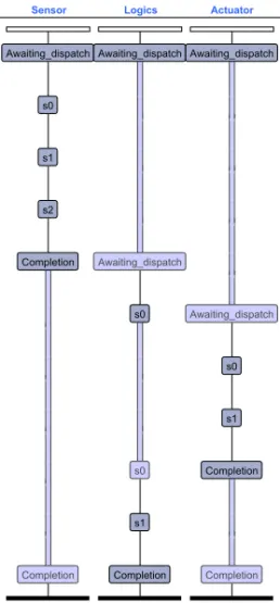
The execution semantics of AADL models is essentially defined in terms of scheduling and execution of threads. An active thread is initially in an “awaiting dispatch” state. Dispatches of the thread are triggered according to the specified dispatch conditions. Dispatches of periodic threads are solely triggered by a clock according to the time interval (period) specified with the thread. Dispatches of aperiodic and sporadic threads are triggered by the ar-rival of an event. In either case, an input-compute-output model of execution is triggered. Input data on in ports is by default locked at the time of dispatch, where new arrivals of data are inaccessible for the remainder of the current dispatch. Output on out ports, on the other hand, is transmitted through the connections at the time of thread completion, deadline, or at specific output times according to an Output T ime property.
2.1.1
Sensor-To-Actuator AADL Example
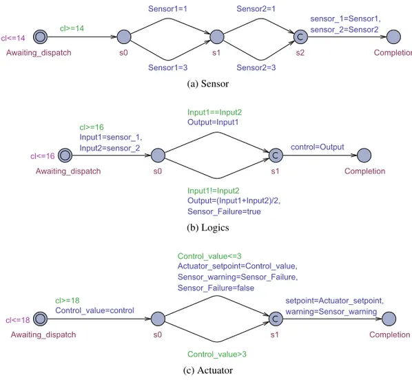
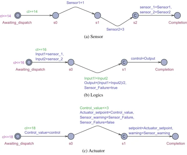
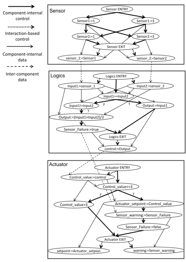
A simplistic example of a sensor-to-actuator system modeled in AADL is pre-sented in Tables 2.2–2.4. A graphical representation of the model is prepre-sented in Fig. 2.1 to facilitate comprehension.
Ha rdw ar e Softw ar e Actua tor Lo gics p ro p erties Di spa tch_ Pr ot oc ol => Per iodi c; Per iod => 1 8 ms ; Priorit y => 0 ; Comput e_ Ex ec ut ion_Ti me => 1 ms .. 2 ms ; Comput e_ Dead line => 1 8 ms ; ann ex beha vior_ specif ic at ion {** stat es s0 : i ni ti al s ta te ; s1 : fi na l s ta te ; tr ansitio n s s0 [1] -[ Con tr ol_v al ue <= 3 ]-> s1 { Actuat or _se tpoi n t:= Con tr ol_v al ue ; Sensor _w arni ng := Sensor _F ai lur e ; Sensor _F ai lur e:=f al se}; s0 [0] -[ Con tr ol_v al ue >3 ]-> s1 {}; ** }; p ro p erties Di spa tch_Pr ot oc ol => Per iodi c; Per iod => 1 6 ms ; Priorit y => 1 ; Comput e_ Ex ec ut ion_Ti me => 1 ms .. 2 ms ; Comput e_ Dead line => 1 6 ms ; ann ex beha vior_ specif ic at ion {** stat es s0 : i ni ti al s ta te ; s1 : fi na l s ta te ; tr ansitio n s s0 [1] -[I npu t1 == Inpu t2 ]-> s1 {Out put :=I npu t1 }; s0 [0] -[I npu t1 != Inpu t2 ]-> s1 {Out put :=( Inpu t1 + Inpu t2 )/2 ; Sensor _F ai lur e:=t rue }; ** }; Sens or p ro p erties Di spa tch_Pr ot oc ol => Per iodi c; Per iod => 1 4 ms ; Priorit y => 2 ; Com put e_ Ex ec ut ion_Time => 1 ms .. 2 ms ; Comput e_ Dead line => 1 4 ms ; ann ex beha vior_ specif ic at ion {** stat es s0 : i ni ti al s ta te ; s1 : st at e; s2 : fi na l s ta te ; tr ansitio n s s0 -[ ]-> s1 {Sensor1 :=1}; s0 -[ ]-> s1 {Sensor1 :=3}; s1 -[ ]-> s2 {Sensor2 :=1}; s1 -[ ]-> s2 {Sensor2 :=3}; ** }; contr ol Sens or_F ai lur e se n so r_1 se n so r_2 setpoi n t w arnin g La tency => 0 ms .. 4 ms; La tency => 0 ms .. 4 ms; La tency => 1 ms .. 6 ms; Pr oces so rPla tf orm RAM primary_sen so r secondar y_sens or CA N p ro p erties Scheduli ng _Pr ot oc ol => Hi ges t_Pr ior it y_ Fir st ; Pr ee mp ti ve_ Scheduler => tru e ; Actua l_Pr oce ssor _B indi ng => ( re fer ence (pr oce ssor Pl at for m )) app lies t o soft w ar e; actua tor dis pla y Concurr ency _Con tr ol_Pr ot oco l=> Sem ap hor e;
Table 2.2 presents a system composed of a software process and a hardware platform that is connected to two sensors, an actuator, and a display through a CAN (Controller Area Network) bus. The Actual Processor Binding property specifies that the process is allocated to the processor.
Table 2.2: AADL sensor-to-actuator system component. system SensorToActuator
end SensorToActuator;
system implementation SensorToActuator.Impl subcomponents
software: process ApplicationSoftware.Impl; processorPlatform: processor ProcessorPlatform.Impl; primarySensor: device primary sensor;
secondarySensor: device secondary sensor; electric actuator: device actuator; digital display: device display; CAN bus: bus CAN; connections
CAN Processor: bus access processorPlatform.external bus –>CAN bus; CAN Sensor1: bus access primarySensor.external bus –>CAN bus; CAN Sensor2: bus access secondarySensor.external bus –>CAN bus; CAN Actutator: bus access electric actuator.external bus –>CAN bus; CAN Display: bus access digital display.external bus –>CAN bus; properties
Actual Processor Binding =>(reference (processorPlatform)) applies to software; end SensorToActuator.Impl;
The description of the software process is presented in Table 2.3. The process is composed of three threads, Sensor, Logics, and Actuator, that are connected by five port connections, sensor 1, sensor 2, control, setpoint, and warning. Each port connection is declared as immediate, i.e., the sending thread writes data to the connection at the time of its execution completion. Connections sensor 1, sensor 2, and control are also associated with a latency property that specifies the expected minimum and maximum duration from when data is written by the sender to when it is read by the receiver. Moreover, the process contains a data component, Sensor Failure, that is shared between
Logicsand Actuator.
Sensor, as specified by its interfaces, properties, and behavioral specifi-cation, periodically outputs two integers that represent outputs from the two sensor devices. For simplicity, each sensor may either output the value “1” or the value “3”. These values are transmitted to Logics through connections
sensor 1and sensor 2. Logics, as specified by its interfaces, properties, and behavioral specification, periodically uses these outputs to compute a control signal for positioning of the actuator device, where the mean of the two sen-sor values is used if they differ whereas the value from the primary sensen-sor is used if they are considered as equal. If the sensor values differ, the shared data component Sensor Failure is set. Actuator finally acts as an interface to the actuator and display, which periodically reads incoming requests and controls the actuator and display accordingly with one exception. If the received con-trol signal is below or equal to the value of three, Actuator positions the device accordingly and displays the state of Sensor Failure. If the signal is higher, no actions are performed.
Table 2.3: AADL sensor-to-actuator software components. process ApplicationSoftware
features
Actuator value: out data port Base Types::Integer; Display warning: out data port Base Types::Boolean; end ApplicationSoftware;
process implementation ApplicationSoftware.Impl subcomponents
sensor: thread Sensor.Impl; logics: thread Logics.Impl; actuator: thread Actuator.Impl; sensorFailure: data Sensor Failure; connections
sensor 1: port sensor.Sensor1 –>logics.Input1{Timing =>Immediate; Latency =>0ms .. 4ms;}; sensor 2: port sensor.Sensor2 –>logics.Input2{Timing =>Immediate; Latency =>0ms .. 4ms;}; control: port logics.Output –>actuator.Control value{Timing =>Immediate; Latency =>1ms .. 6ms;};
setpoint: port actuator.Actuator setpoint –>Actuator value{Timing =>Immediate;}; warning: port actuator.Sensor warning –>Display warning{Timing =>Immediate;}; logics access: data access Logics.Sensor Failure –>sensorFailure;
actuator access: data access actuator.Sensor Failure –>sensorFailure; end ApplicationSoftware.Impl;
thread Sensor features
Sensor1: out data port Base Types::Integer; Sensor2: out data port Base Types::Integer; properties
Dispatch Protocol =>Periodic; Period =>14 ms; Priority =>2; Compute Execution Time =>1 ms .. 2 ms; Compute Deadline =>14 ms; end Sensor;
thread implementation Sensor.Impl annex behavior specification {** states s0 : initial state; s1 : state; s2 : final state; transitions s0 –[ ]–>s1 {Sensor1:=1}; s0 –[ ]–>s1 {Sensor1:=3}; s1 –[ ]–>s2 {Sensor2:=1}; s1 –[ ]–>s2 {Sensor2:=3}; **}; end Sensor.Impl; thread Logics features
Input1: in data port Base Types::Integer; Input2: in data port Base Types::Integer; Output: out data port Base Types::Integer;
Sensor Failure: requires data access Sensor Failure{Access Right =>read write;}; properties
Dispatch Protocol =>Periodic; Period =>16 ms; Priority =>1; Compute Execution Time =>1 ms .. 2 ms; Compute Deadline =>16 ms; end Logics;
thread implementation Logics.Impl annex behavior specification {** states s0 : initial state; s1 : final state; transitions s0 [1] –[Input1==Input2]–>s1 {Output:=Input1}; s0 [0] –[Input1!=Input2]–>s1 {Output:=(Input1+Input2)/2; Sensor Failure:=true}; **}; end Logics.Impl; thread Actuator features
Control value: in data port Base Types::Integer; Actuator setpoint: out data port Base Types::Integer; Sensor warning: out data port Base Types::Boolean;
Sensor Failure: requires data access Sensor Failure{Access Right =>read write;}; properties
Dispatch Protocol =>Periodic; Period =>18 ms; Priority =>0; Compute Execution Time =>1 ms .. 2 ms; Compute Deadline =>18 ms; end Actuator;
annex behavior specification {** states s0 : initial state; s1 : final state; transitions
s0 [1] –[Control value<=3]–>s1 {Actuator setpoint:=Control value; Sensor warning:=Sensor Failure; Sensor Failure:=false};
s0 [0] –[Control value>3]–>s1 {}; **};
end Actuator.Impl; data Sensor Failure properties
Concurrency Control Protocol =>Semaphore; end Sensor Failure;
The description of the different hardware components, i.e., the processor platform, CAN bus, sensors, actuator, and display, is finally presented in Ta-ble 2.4. The processing platform has embedded RAM (Random Access Mem-ory) and a fixed-priority preemptive scheduler. The processor, sensors, actua-tor, and display require bus access to the CAN bus.
Table 2.4: AADL sensor-to-actuator hardware components. processor ProcessorPlatform
features
external bus: requires bus access CAN; end ProcessorPlatform;
processor implementation ProcessorPlatform.Impl subcomponents
MemBank: memory RAM; properties
Scheduling Protocol =>Highest Priority First; Preemptive Scheduler =>true; end ProcessorPlatform.Impl;
memory RAM end RAM; bus CAN end CAN;
device primary sensor features
end primary sensor; device secondary sensor features
external bus: requires bus access CAN; end secondary sensor;
device actuator features
external bus: requires bus access CAN; end actuator;
device display features
external bus: requires bus access CAN; end display;
2.2
Control and Data Flow Analysis
A traditional approach of detecting erroneous behaviors of software systems is to analyze their control and data flows [35]. The control flow of a software sys-tem corresponds to the order in which the software instructions are executed. The data flow corresponds to the order in which data variables are assigned with values by instructions and how these variables and values subsequently are used. Control flow analysis is therefore a prerequisite for data flow analy-sis, since the flow of data is dependent on the order in which the instructions are executed. These flows are essential to the behavior of the system as they determine how system input is transformed into system output.
An AADL model expresses control and data flows throughout the software architecture in terms of component connections, subprogram calls, data ac-cesses, and behavior specifications. For example, behavior specifications are composed of state transitions, each of which corresponds to an execution order of instructions: the guard of the transition is first computed and, if evaluated to true, the action (or sequence of actions) is executed. The control flow is typically represented by a directed graph in the analysis [36], where the ver-tices represent the instructions and the directed arcs between verver-tices represent the order of execution. Guards and actions are the executable instructions of behavior specifications and consequently yield the vertices of the control flow graph. An illustration of the control flow graph of a behavior specification is presented in Fig. 2.2. The “ENTRY” vertex represents the point through which