Research
Sulphide-induced stress corrosion
cracking and hydrogen absorption in
copper exposed to sulphide and chloride
containing deoxygenated water at 90°C
2020:01
Authors: Richard Becker1
Antti Forsström2
Yuriy Yagodzinskyy2
Hannu Hänninen2
Mikko Heikkilä3
1. Studsvik Nuclear AB, Sweden
2. Aalto University, School of Engineering,
Department of Mechanical Engineering, Espoo, Finland 3. Helsinki University, Faculty of Science,
SSM perspektiv Bakgrund
Den metod som den svenska kärnkraftsindustrin planerar att tillämpa för att slutförvara använt kärnbränsle kallas för KBS-3 och bygger på tre skyddsbarriärer: kopparkapslar, bentonitbuffert och det svenska urber-get. I den aktuella KBS-3-utformningen kommer det använda kärnbräns-let att placeras i en insats av gjutjärn som omgärdas av ett 50 mm tjockt kopparhölje. Gjutjärnsinsatsen ger mekanisk hållfasthet och strålskydd, medan kopparhöljet utgör kapselns korrosionsbarriär. Kapseln ska sedan deponeras i ett förvar i Forsmarks urberg på ett djup på ca 500 m, där varje kapsel omsluts av en bentonitbuffert, främst för att begränsa transport av grundvatten till och från kapselytan. Vid utvärdering av KBS-3-systemets långsiktiga skyddsförmåga är förståelsen för långtid-sutvecklingen av processer som kan påverka kapselns inneslutningsfunk-tion, till exempel lokala korrosionsprocesser såsom spänningskorrosion och gropkorrosion under reducerande kemiska betingelser, av stor vikt. Forskningsstudier som kan bidra till att belysa förutsättningar och utöka förståelsen för dessa typer av fundamentala processer och mekanismer utgör därför viktiga underlag i sammanhanget. För att avgöra betydelsen av enskilda resultat för bedömningen av ett KBS-3-slutförvars långsik-tiga strålsäkerhet kräver dock ett beaktande av aktuell slutförvarsmiljös förhållanden och långsiktiga utveckling och de i detta sammanhang för processen viktigaste parametrarna. För gropkorrosion under reduc-erande betingelser är dessa i första hand koncentrationer och flux av vätesulfidjoner, samt även kloridhalt, vilka kräver en förståelse och analys av både grundvattenkemiska förhållanden och transportprocesser i kapselns närhet. För spänningskorrosion, vilket även förutsätter före-komst av dragspänningar i höljet, fordras också, utöver parametrarna som styr förutsättningarna för gropkorrosion i slutförvarsmiljö, en förståelse av lasterna som kan förekomma i slutförvaret samt utvecklin-gen av spänningsförhållanden i kapseln.
Resultat
Spänningskorrosion av OFP-koppar i reducerande sulfidmiljö har studer-ats med SSRT-metoden, i vilken kopparproverna utsätts för dragspännin-gar under långsam belastning, vid 90 oC och olika sulfidkoncentrationer (0,001 M respektive 0,00001 M). Vid den högre sulfidkoncentrationen observerades interkristallina defekter i kopparmaterialet vilket inte noterades i prover som exponerats vid den lägre sulfidkoncentrationen. I samma försöksmiljö exponerades även obelastade kopparprover, både basmaterial och koppar från svetsat material, för att utröna effekten av mekanisk pålastning på omfattningen av väteladdning i kopparmate-rialet. Högst väteladdning observerades i de obelastade, svetsade kop-parproverna. För basmaterialet konstaterades att mekaniskt laddade kopparprover uppvisar en något högre vätehalt efter exponering än de obelastade proverna. För obelastade prover exponerade vid den lägre sulfidkoncentrationen noterades en lägre vätehalt efter exponering än före. Det observerades att sulfideringen av oxidfilmer som bildats på
kopparproverna före exponering var väldigt effektiv. En utförligare sam-manfattning av resultaten återfinns i ”Summary” i inledningen av rap-porten.
Relevans
Detta forskningsprojekt är en fortsättning på en SSM-finansierad studie (SSM 2017:02) som syftade till att belysa kemiska och mekaniska förutsättningar för spänningskorrosion av syrefri, fosfordopad koppar, så kallad OFP-koppar, i sulfidmiljö under kemiskt reducerande förhål-landen genom långsam belastning av kopparprover i lösningar med varierad sulfidkoncentration (SSRT; Slow strain rate testing). Denna fortsättningsstudie fokuserar på att bekräfta och noggrannare inringa de gränsvärden på sulfidkoncentration och dragspänningar under vilka spänningskorrosion inte kunde observeras i det föregående projektet, samt även studera omfattningen av väteladdning som följd av sulfidkor-rosion i både pålastade och obelastade kopparprover.
Behov av vidare forskning
Spänningskorrosion är en lokal korrosionsform som är förhållandevis komplex då den innefattar en samverkan mellan kemiska och mekaniska förhållanden. Föreliggande studie har bidragit till att uppskatta både kemiska, främst sulfidkoncentration, och mekaniska gränsvärden under vilka processen inte kan observeras. Mot bakgrund av spänningskor-rosionsprocessers komplexitet anser SSM att det finns en relevans av att fortsatt studera spänningskorrosion av koppar under kemiskt reduc-erande betingelser, liksom processens mekanistiska förutsättningar samt även mekanismer för väteladdning av koppar. En ur ett KBS-3-slutför-varsperspektiv relevant inriktning skulle kunna innefatta experimentella studier med högre känslighet och detektionsförmåga som simulerar väteladdning av koppar i slutförvarsmiljö, samt inverkan av väteladdning i perspektivet spänningskorrosion.
Projektinformation
Kontaktperson SSM: Henrik Öberg Referens: SSM2018-2132 / 3030045-44
SSM perspective Background
The concept that the Swedish nuclear power industry plans to utilise for the final disposal spent nuclear fuel is called KBS-3 method, which is based on three different barriers to prevent spreading of radioactive substances: copper canisters, bentonite buffers and the surrounding Swedish bedrock. In the current KBS-3 design, the spent nuclear fuel will be placed in cast iron inserts which will be protected by a 50 mm thick copper shell. The cast iron insert provides mechanical strength and radiation shielding, while the copper constitutes the corrosion barrier of the canister. The canisters should then deposited in a reposi-tory at the Forsmark site at a depth of about 500 m, where each can-ister is enclosed by a bentonite buffer, primarily to limit transport of groundwater to and from the canister’s surface. When evaluating The KBS-3 system’s long-term protective capability, the understanding of long-term processes that can affect the canister containment function, for example, local corrosion processes such as stress corrosion cracking and pitting corrosion under reducing chemical conditions, is of great importance. Research studies can help elucidate conditions and expand understanding of these types of fundamental processes and mecha-nisms, which therefore constitute important evidence in this context. To determine the meaning of individual experimental results for the assessment of a long-term KBS-3 repository performance however, the radiation safety analysis requires consideration of the current environ-mental conditions in the repository environment, and the long-term development of those conditions, which in this context are represented by the most important parameters for the processes. For pitting corro-sion during reducing conditions, those are primarily concentrations and fluxes of hydrogensulphide ions, as well as the chloride content, which need to be based on understanding and analysis of both groundwater chemical conditions and transport processes in the vicinity of a canister. For stress corrosion cracking, which additionally requires occurrence of tensile stresses in the shell in addition to the parameters controlling the conditions for pitting corrosion in the repository environment, such parameters need to be based on an understanding of the loading con-ditions that may occur in the repository as well as the development of stresses in the canister shell.
Results
Stress corrosion of OFP copper in a reducing sulphide environment has been studied with the SSRT method, in which the copper samples are subjected to tensile stresses under slow loading conditions, at 90ºC and at the same time exposed for different sulphide concentrations (0.001 M and 0.00001 M, respectively). At the higher sulphide concentra-tion level, intercrystalline defects in the copper material were observed, which was not the case for the samples exposed at the lower sulphide concentration level. Unloaded samples from copper base material as well as from welded copper material were also exposed in the same
experi-mental environment, in order to determine the effect of mechanical loading on the extent of hydrogen charging of the copper material. The highest hydrogen charging was observed in the unloaded welded copper samples. For the base material it was found that mechanically loaded copper samples exhibit a slightly higher hydrogen content after expo-sure as compared with the unloaded samples. For the unloaded samples exposed at the lower the sulphide concentration level, it was noted that hydrogen content was lower after exposure compared to before expo-sure. It was observed that the sulphidation of oxide films formed on the copper samples before exposure were very effective. A more detailed summary of the results can be found in “Summary” section in the begin-ning of the report.
Relevance
This research project is a continuation of an SSM-funded study (SSM 2017: 02) aimed at elucidating chemical and mechanical conditions required for stress corrosion of oxygen-free, phosphorus-doped copper, so-called OFP copper, in a sulphide environment under chemically reducing conditions by slow loading of copper samples in solutions with varied sulphide concentration (SSRT; Slow Strain Rate Testing). This continuation study focuses on confirming and more accurately estab-lishing the limiting values for sulphide concentration and tensile stress, below which stress corrosion could not be observed in the previous project, and also to study the extent of hydrogen charging as a result of sulphide corrosion in both loaded and unloaded copper samples. Need for further research
Stress corrosion is a form of local corrosion that can be regarded as complex as it involves an interaction between both chemical and mechanical conditions. The present study has contributed to estimating both chemical, mainly sulphide concentration, and mechanical limit-ing values below which the process cannot be observed. Considerlimit-ing the complexity of stress corrosion as a process, SSM considers it to be relevant to continue these studies under chemical reducing conditions, along with the mechanical conditions related to the process, as well as also covering mechanisms for the hydrogen loading of copper. A direc-tion of these studies, based on a KBS-3 final repository relevance, could be experimental studies aimed at higher sensitivity and detection capa-bility which simulate hydrogen charging of copper corresponding to the final repository environment, as well as the effect of hydrogen charging in the perspective of stress corrosion.
Projektinformation
Kontaktperson SSM: Henrik Öberg Referens: SSM2018-2132 / 3030045-44
2020:01
Authors: Richard Becker1
Antti Forsström2
Yuriy Yagodzinskyy2
Hannu Hänninen2
Mikko Heikkilä3
1. Studsvik Nuclear AB, Sweden
2. Aalto University, School of Engineering,
Department of Mechanical Engineering, Espoo, Finland 3. Helsinki University, Faculty of Science,
Department of Chemistry, Helsinki, Finland
Sulphide-induced stress corrosion
cracking and hydrogen absorption in
copper exposed to sulphide and chloride
containing deoxygenated water at 90°C
This report concerns a study which has been conducted for the Swedish Radiation Safety Authority, SSM. The conclusions and view-points presented in the report are those of the author/authors and do not necessarily coincide with those of the SSM.
Sulphide-induced stress corrosion cracking and
hy-drogen absorption in copper exposed to sulphide
and chloride containing deoxygenated water at
90°C
Richard Becker1, Antti Forsström2, Yuriy Yagodzinskyy2, Mikko Heik-kilä3, Hannu Hänninen2
1. Studsvik Nuclear AB, Sweden
2. Aalto University, School of Engineering, Department of Mechanical En-gineering, Espoo, Finland
3. Helsinki University, Faculty of Science, Department of Chemistry, Hel-sinki, Finland
Table of Contents
1. Introduction and background ... 3
2. Experimental work ... 4
2.1. Test materials and specimens ... 4
2.2. Autoclave exposures ... 5
2.3. Specimen examination ... 6
2.4. Hydrogen thermal desorption spectroscopy (TDS) ... 7
2.5. X-ray diffraction (XRD)... 7
3. Results ... 8
3.1. SSRT specimen exposed to the high sulphide environment (exposure #8) ... 8
3.1.1. Optical and SEM observations... 8
3.1.2. EBSD of the surface defects ... 15
3.2. SSRT specimen exposed to the low sulphide environment (exposure #9) ... 17
3.2.1. Optical and SEM observations... 17
3.3. Unloaded coupon specimens and Cu2S film characterization ... 20
3.3.1. High sulphide environment (exposure #8) ... 22
3.3.2. Low sulphide environment (exposure #9) ... 24
3.3.3. Pre-oxidized specimens ... 25
3.3.4. Weld metal specimens ... 27
3.4. Results of hydrogen thermal desorption spectroscopy (TDS) ... 30
3.5. Sulphide and oxide film XRD characterization... 36
4. Discussion ... 38
5. Conclusions ... 41
References ... 43
Summary
Stress corrosion cracking (SCC) and corrosion of copper in sulphide and chloride contain-ing deoxygenated water was studied at 90°C in sulphide concentrations of 0.001 M and 0.00001 M using slow strain rate tensile testing (SSRT) up to 9 % strain. A set of unloaded coupon specimens was simultaneously exposed to the same environments. Several inter-granular defects were found in the SSRT specimen exposed to the high sulphide environ-ment, but similar defects were not found in the low sulphide conditions. Only some corro-sion on grain boundaries and slip lines was visible. The hydrogen content measurements show an increase in hydrogen uptake of the mechanically loaded SSRT specimens in both conditions when compared to the unloaded coupon specimens and unexposed as-supplied state of the studied oxygen-free phosphorous alloyed copper (Cu-OFP). In the low sulphide environment, the difference between the mechanically loaded specimen and the mechani-cally unloaded coupon specimens is pronounced, likely because of hydrogen outgassing of the unloaded coupon specimens. This results in hydrogen content of the mechanically un-loaded specimens being lower than the as-supplied state. However, it seems that hydrogen uptake of copper is dependent on both the sulphide concentration and the plastic defor-mation. The highest hydrogen content, on the other hand, was measured in unloaded cou-pon specimens of friction stir welded (FSW) copper, welded in air without shielding gas, and tested in the high sulphide environment. The air-welded FSW specimens are a special case since the embedded oxide particles in the weld act as local hydrogen trapping sites. It was also found that the oxide particle stringers are selectively attacked in the sulphide so-lution. A relatively thick air-formed oxide film covers the canisters when deposited, which will transform into a Cu2S film in the repository conditions. Thus, some of the unloaded coupon specimens were pre-oxidized. It was observed that the conversion of the pre-exist-ing oxide film into a Cu2S film occurs quickly and the transformation is almost 100 % efficient. The Cu2S film that formed on the pre-oxidized specimens was very similar to the films formed on all the other copper specimens. In the report, the structure and properties of the Cu2S film, susceptibility to sulphide-induced SCC, and hydrogen uptake of copper in reducing, anoxic repository conditions are discussed.
Keywords
copper, stress corrosion cracking, sulphide corrosion, sulphide film, hydrogen absorption, friction stir welding
1. Introduction and background
Stress Corrosion Cracking (SCC) of copper in conditions relevant to final repository of spent nuclear fuel is considered possible, but not likely to occur [1]. The key agents known to induce SCC of copper (ammonia, acetate, nitrite) are expected to be present during the aerobic phase of disposal, but not in sufficient amounts to induce SCC. During the long anaerobic phase, sulphide ions (SH-) in groundwater will be transported to the canister sur-face by diffusion through the saturated bentonite, which causes sulphidation of the copper and general corrosion on the canister surface. The corrosion rate is limited by the mass transport of sulphide ions through the bentonite buffer [1]. However, before full saturation of the bentonite, the mass transport is less limited, and conditions for sulphide producing microbial activity in the buffer are more favourable.
Indications of sulphide-induced SCC of copper have been reported at a sulphide concen-tration of 0.01 M [2], which is considerably higher than typically expected in the repository conditions. However, a recent collaboration study between Studsvik Nuclear AB, Sweden, and Aalto University, Finland, involving slow strain rate tensile testing (SSRT) of Cu-OFP in 0.1 M NaCl containing solution with varying content of S2- (added as Na
2S) from 0.001 M to 0.00001 M [3, 4] showed that cracking can occur at sulphide concentration of 0.001 M. This is an order of magnitude lower than the value reported before [2], but still higher than the highest measured sulphide ion concentration in the Swedish planned site for final repository in Forsmark (0.00012 M) [5]. The specimens were studied post-testing for hy-drogen uptake. The hyhy-drogen content of copper increased from 0.5 wt.ppm to 1.2 wt.ppm during the short term SSRT testing of two weeks. This may be compared to the maximum allowed hydrogen content of copper in the KBS-3 concept of 0.6 wt.ppm [6]. It should be noted that the hydrogen limit defined in the KBS-3 concept is somewhat arbitrary and has no clear connection to any onset of a degradation process. However, the study [3, 4] sug-gests that SCC cracking of copper in reducing, anoxic sulphide containing environment may involve hydrogen uptake in the copper metal, and that the SCC mechanism may be related to the hydrogen absorption. In all studied conditions, surface defects, not positively attributed to SCC (except for the highest sulphide concentration), were present. The fact that SCC occurred at sulphide ion concentrations close to the expected Forsmark values makes studying sulphide-induced SCC of copper in reducing, anoxic repository conditions important.
The opening of grain boundaries in sulphide-induced SCC of copper may be compared to opening of grain boundaries and hydrogen-enhanced creep of Cu-OFP [7] in electrolytic hydrogen charging. Micro-voids form on the grain boundaries, which are positioned along maximum shear, indicating a process of accommodating the shear stress component, e.g., by grain boundary sliding [7]. It is possible that a similar mechanism is operational in the SCC environment since hydrogen uptake was observed. On the other hand, a simulation study on hydrogen effects on void nucleation in copper shows that hydrogen stabilizes di-vacancies and promotes vacancy cluster formation [8]. Hydrogen prevents the collapse of large vacancy clusters. Impurities and alloying elements of copper such as O, P, S, and Ag contribute to void formation by capturing vacancies [8].
The implications of SCC occurring in the repository could be severe, risking the release of radioactive substances. To estimate the risk of sulphide-induced SCC of copper in detail, longer exposures and lower strain rates are necessary when compared to the previous la-boratory testing [3, 4]. The SCC mechanism of Cu-OFP in the repository conditions is still unknown. Therefore, additional exposures were conducted to study especially the
ox-ide/sulphide film transformation, structure and properties of the Cu2S film, SCC, and hy-drogen uptake of copper under reducing, anoxic repository conditions. The results deepen the understanding of these phenomena in conditions relevant for final disposal of spent nuclear fuel.
2. Experimental work
2.1. Test materials and specimens
The material used in the SSRT tests was phosphorous-alloyed oxygen-free copper (Cu-OFP) cut from the top part of a canister lid [3], delivered originally by the Swedish Nuclear Fuel and Waste Management Co. (SKB) to Studsvik Nuclear AB through co-operation with the Swedish Radiation Safety Authority (SSM). The same material was used in the earlier studies [3, 4]. The chemical composition is shown in Table 1.
Table 1. Specification of chemical composition of Cu-OFP used in the tests (in wt.ppm, except for Cu).
Cu O P Pb Bi As Sb Sn Zn Mn Cr Co Cd Fe Ni Ag Se Te S
99.99 wt-% 1-2 43-60 <1 <1 <1 1 <0.5 <1 <0.5 <1 <1 <1 <1 2 12 <1 <1 6
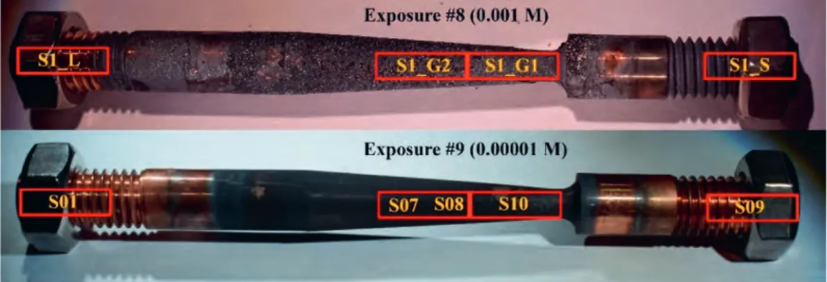
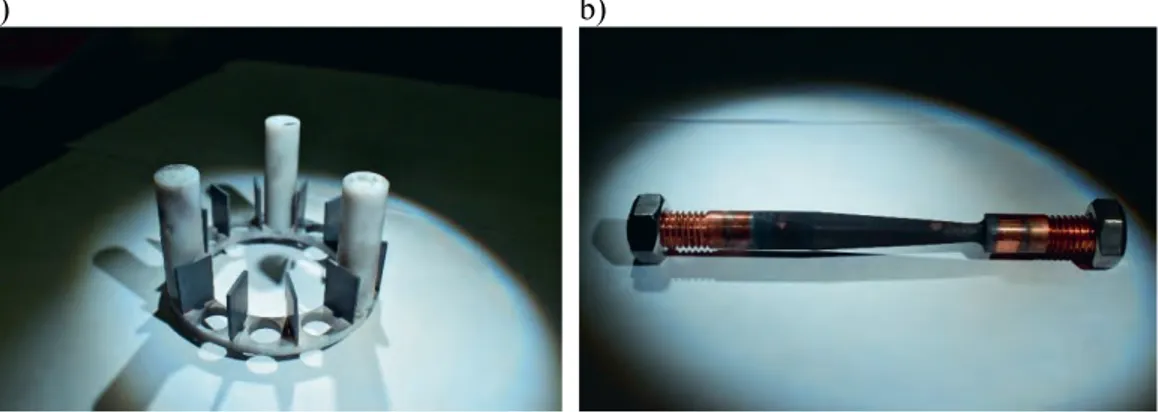
The shape of the SSRT specimens was previously determined by finite-element method (FEM) calculations to obtain a desired strain in the gauge section [3]. The maximum strain was 9 % in the narrowest section, allowing a 1.3 mm total elongation. The main dimensions were diameter of ø4.2 mm at the narrowest section, ø8.0 mm at the thick section, and 35 mm length of the tapered section [3]. The tested SSRT specimens, post exposure, are shown in Figure 1 together with the locations of samples cut for hydrogen content measurements by thermal desorption spectroscopy (TDS).
In addition to the SSRT tensile specimens, additional mechanically unloaded coupon spec-imens were exposed simultaneously to the same sulphide containing environments. The specimens were then studied for sulphidation and hydrogen uptake. The coupon specimens were cut from the as-supplied base material, as well as from two different canister friction stir welds (FSW) provided by the Swedish Nuclear Fuel and Waste Management Co. (SKB), Sweden, and by Posiva Oy, Finland. The first FSW canister weld was welded in air and provided by SKB, and the second one was welded in argon (Ar) shielding gas and provided by Posiva Oy. However, the welding in both cases was performed by SKB. These welds are named 1W (welded in air) and 2W (welded in argon), respectively, when dis-cussing the results. The FSW coupon specimens were cut in such a manner that the pro-cessing zone where the oxide particle stringers are located were exposed to the environment to reveal a possible Cu2O particle sulphidation and consequent penetration along the oxide particle stringers into the weld metal. In addition, some of the unloaded coupon specimens were pre-oxidized using the method of Aaltonen et al. [9] to simulate a thick copper oxide film, which will be present on the canister surfaces at the time of disposal. The size of the coupon specimens was 20×20×2 mm. Naming of the specimens exposed in each exposure are summarized Appendix I.
Figure 1. SSRT specimen #8 (top) and #9 (bottom) after testing. Locations and naming of TDS samples are marked with red rectangles and yellow text.
2.2. Autoclave exposures
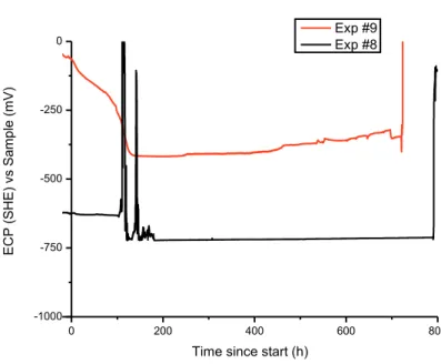
The autoclave apparatus [3] of Studsvik was used to perform two exposures (#8 and #9) in controlled environment with lower strain rate than in the previous testing [3, 4]. In each exposure, the tensile specimen and 12 copper coupons cut from the lid base material and the FSW weld metals were simultaneously exposed. A special holder made of PTFE was constructed for these coupon specimens. The autoclave loop was used to control the tem-perature at 90°C and the test solution at the desired concentration (see Table 2). The chem-istry of the solution was controlled by addition of a dosage solution containing 0.1 M NaCl and the desired amount of Na2S to the main flow. A second dosage flow containing Na2HPO4 and NaH2PO4 was used to control the pH of the solution at 7.2. Several parame-ters were monitored during testing, including the electrochemical corrosion potential (ECP) of the specimens to ensure a stable deoxygenated environment. The ECPs of both expo-sures for the whole duration of the test are shown in Figure 2, while all exposure data is presented in Appendix II. The ECP of specimens #8 and #9 were -720 mV and -370 mV vs the standard hydrogen electrode (SHE), respectively, which indicates that a reducing, anoxic condition existed throughout the full exposures.
Table 2. Target test parameters for the two exposures in the autoclave.
Parameter Target value
Temperature 90°C Cl- (added as NaCl) 0.1 M S2- (added as Na 2S) Exposure #8 1 x 10⁻³ M Exposure #9 1 x 10⁻⁵ M
Autoclave flow rate 1 l/h
Maximum strain 9 %
0 200 400 600 800 -1000 -750 -500 -250 0 EC P (SH E) vs Sam pl e (mV)
Time since start (h)
Exp #9 Exp #8
Figure 2. ECPs of exposures #8 and #9.
Each exposure experienced some minor incidents that needs special consideration: Approximately four days into exposure #8 at two separate occasions, the autoclave
ex-perienced loss of main pump flow, followed by loss of heating. The first occasion lasted for approximately ten hours, during which the autoclave cooled to ambient conditions. Deformation of the SSRT specimen was at this point still elastic. The second occasion occurred shortly after the first one, while no additional strain was applied to the SSRT specimen. Following this, the main pump was replaced, and the exposure saw no more incidents.
Right before the end of exposure #9, the dosage solution containing the buffer solution was halted, meaning that for the last day only the chloride/sulphide solution was added to the main flow.
As the first incident occurred during the elastic phase of deformation and the second oc-curred close to the end of the exposure, the two incidents were deemed not to have any critical impact on the quality of the results.
2.3. Specimen examination
Following the exposures, both the SSRT and coupon specimens were removed from the autoclave and transported from Studsvik AB to Aalto University where the analytical ob-servations of the Cu2S films and surface defects, as well as the hydrogen measurements were performed. Following the exposure, but prior to the examinations, the SSRT speci-mens were primarily only cleaned by rinsing with ethanol without removal of the Cu2S films. After initial observation of the SSRT specimens, additional ultrasonic cleaning in ethanol was applied, which removed the Cu2S films quite easily. The Cu2S films and sur-face defects were observed first with optical microscopy and macroscopy, and then by scanning electron microscopy (SEM). The SEM observations were performed with a Zeiss Merlin VP Compact field emission gun SEM (FEG SEM) equipped with a Bruker xFlash 6|30 energy-dispersive spectrometry (EDS) detector. The electron backscatter diffraction (EBSD) measurements were performed with a Zeiss Ultra 55 FEG SEM equipped with
HKL Nordlys II EBSD detector. Specimen preparation for EBSD involved polishing down to ¼ µm diamond paste and vibratory polishing in colloidal silica for at least 48 h to remove deformation from the surfaces. Additional measurements were performed at Helsinki Uni-versity for some of the coupon specimens with x-ray diffraction (XRD) to study the struc-ture of the Cu2S films.
2.4. Hydrogen thermal desorption spectroscopy (TDS)
The unloaded reference coupon specimens and SSRT specimens were studied for hydrogen uptake with thermal desorption spectroscopy (TDS) at Aalto University. The apparatus is based on a precise mass-spectrometry measurement of gas partial pressure in ultra-high vacuum (UHV) chamber, equipped with a vacuum friendly internal furnace. It allows the measurement of hydrogen desorption in temperature range of 20 to 1200oC with a con-trolled heating rate between 1 and 10oC/min. Normal vacuum in the UHV chamber is about 5×10⁻⁹ mbar, providing the possibility to monitor hydrogen in copper at concentration down to 0.02 wt.ppm. After conversion of the measured partial pressures of hydrogen to desorp-tion rate (in at.ppm or wt.ppm per second), the hydrogen concentradesorp-tion is calculated as the area under the measured TDS curve.
Samples for the TDS measurements were cut with electro discharge machining (EDM) from different parts of the tapered SSRT specimens (see Figure 1) and mechanically from the copper coupon specimens after exposure to the sulphide-containing environments. The TDS samples cut from the SSRT specimens were taken from the threaded parts, subjected to the minimum load, and from the narrow gauge-section, subjected to the maximum load. All the different types of exposed coupon specimens were measured for hydrogen uptake, meaning the base material, the two different FSW welds, and the pre-oxidized coupons. Additionally, reference TDS samples were cut from the as-supplied base material and from the air-welded FSW weld.
In order to remove the surface layer affected by the EDM cutting or mechanical cutting, the samples for TDS were mechanically ground to size of about 0.9×3.8×10.0 mm, finish-ing with 2000 grit silicon carbide (SiC) paper. Some TDS specimens, cut from the copper coupons, were ground only from one side leaving the Cu2S layer on the other side unaf-fected, which provides conditions for estimation of hydrogen distribution in the Cu2S film and copper substrate. Hydrogen uptake in the Cu2S film itself was also measured from Cu2S powder removed from one of the copper coupon specimens, which was exposed to the high sulphide environment. Just before TDS measurement, the samples (except for the powder specimen) were cleaned in acetone in an ultrasonic bath for one minute and dried in pure helium gas flow.
2.5. X-ray diffraction (XRD)
The structure of the films formed on the copper surface was studied with x-ray diffraction (XRD) analysis. The x-ray diffraction measurements were performed at Helsinki Univer-sity with PANalytical X’Pert Pro MPD in grazing incidence geometry (GIXRD) using x-ray mirror and parallel plate collimator for the parallel beam optics, and 1° constant incident angle. One of the films (from coupon specimen B3_HS) was removed from the copper substrate, ground to fine powder, and then measured in Bragg-Brentano geometry using programmable incident and anti-scatter slits and PIXcel 1D detector.
3. Results
3.1. SSRT specimen exposed to the high sulphide environment
(exposure #8)
3.1.1. Optical and SEM observations
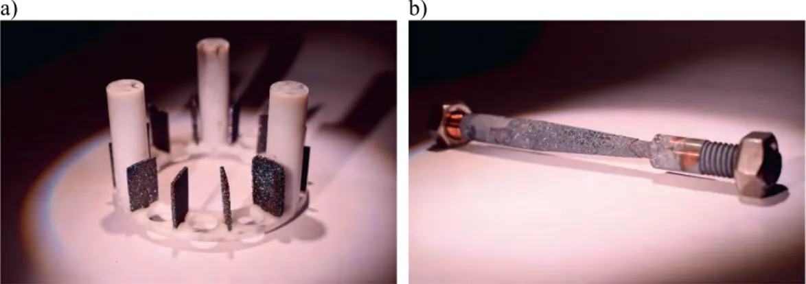
SSRT specimen #8 was tested in 0.001 M sulphide solution at 90°C together with the cou-pon specimens. The general appearance of the coucou-pon specimens and the tensile specimen after testing is shown in Figure 3. A thick, multi-layer Cu2S film formed on the SSRT specimen, as well as on the coupon specimens. The films are different in their structure since the film on the SSRT specimen was repeatedly detached from the surface during deformation of the specimen, whereas the film on the unloaded coupon specimens did not detach as easily. Figure 4 shows macrographs of the Cu2S film formed on the tensile spec-imen. The films are very brittle, and thus crack easily already during tensile testing.
a) b)
a) b)
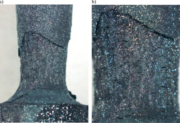
Figure 4. Macrographs of specimen #8 after testing in the high sulphide environment.
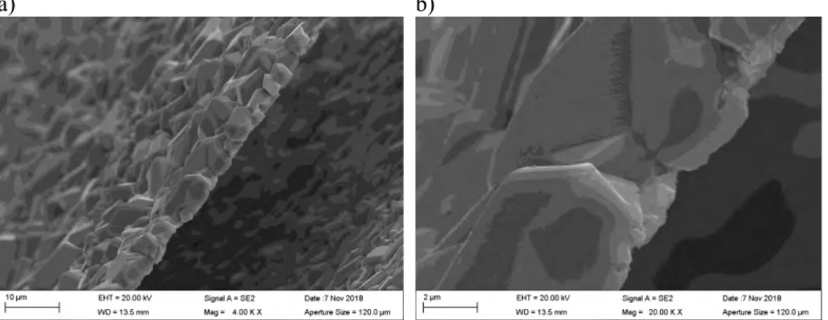
The film structures and compositions were examined in detail using scanning electron mi-croscopy (SEM) and energy dispersive x-ray spectroscopy (EDS). The SEM images in Fig-ure 5 show how the different layers of the Cu2S film crack and detach from the copper surface. It is evident from the wavy appearance of the outer cracked Cu2S film that the films detach due to deformation of the tensile specimen. Similar wavy appearance was not observed on the unloaded coupon specimens. However, the volume of the Cu2S crystals is larger than the volume of the copper substrate, which may also result in a tendency of the Cu2S film to detach easily.
There are at least three Cu2S film layers, with different crystal morphologies, formed on the SSRT specimen. As the Cu2S film detaches from the copper surface, a new film forms underneath the detached one. The Cu2S crystals grow directly from the copper surface. The crystals were confirmed by EDS to contain Cu and S, meaning that they are most likely Cu2S crystals, later confirmed by the XRD measurements. The surface beneath the crystals, visible for example in Figure 5 d) was confirmed by EDS to be Cu.
a) b)
c) d)
Figure 5. a) General view of SSRT specimen #8. b) Several Cu2S film layers formed. c) The films detach from the copper surface due to deformation of the specimen. d) The Cu2S crys-tals grow directly from the Cu surface.
Figure 6 shows details of the Cu2S films. The films crack perpendicular to the loading direction, as shown in Figure 6 a) and b). The cracking has revealed another layer of Cu2S film beneath the top film with a different crystal morphology. The outer detached film has much smaller crystal size, and the size of the crystals varies greatly, whereas the inner (also detached) film has a more consistent grain size and larger crystals. The two morphologies are shown in greater detail ion Figures 6 c) and d). Side-view of the inner detached Cu2S film is shown in Figure 7. A single layer of Cu2S crystals has formed and it was detached from the copper surface. Cracking of the film has occurred intergranularly. Since the film is very brittle, the crystals are most likely held in place partly by mechanical locking.
a) b)
c) d)
Figure 6. a) The Cu2S films crack perpendicular to the loading direction. b) Different layers of films have different crystal morphologies. c) The inner (but still detached) film has larger crystals and the size of the crystals does not vary much. d) The outer film has smaller crystals and their size varies more.
a) b)
Figure 7. Side view of the inner detached Cu2S film.
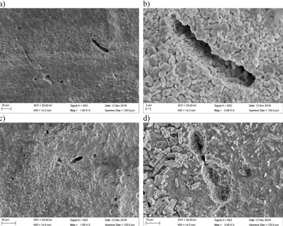
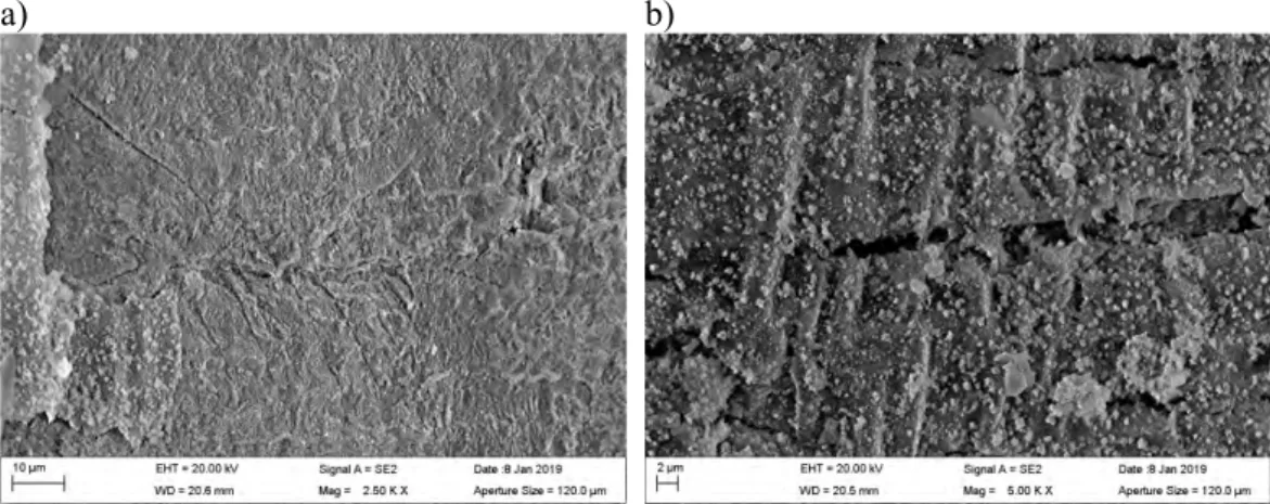
Figure 8 shows details of the Cu2S crystal growth on the Cu surface. The crystals grow directly from the copper surface, and therefore form a roughened copper surface when the Cu2S film is removed. No pitting corrosion was found. However, observation of the Cu surface beneath the Cu2S films revealed the existence of several surface defects resembling
the cracking of grain boundaries found in [3, 4]. These surface defects, shown in Figure 9, form underneath the Cu2S film, and the Cu2S crystal growth is also observed inside the defects.
After initial observations, the Cu2S films were removed by ultrasonic cleaning. This re-vealed more surface defects underneath. Some of them are shown in Figure 10. The Cu2S crystals grow inside the open defects, but in many cases the cracks are not completely filled with the corrosion products, allowing the transportation of corrosion agents in the solution inside the defects. In many locations, small pitting-like corrosion attack, as shown in Figure 11, was present on the grain boundaries. These corrosion defects may later form larger defects on the grain boundaries by joining as shown in Figure 10 d). Similar defects were not found in the unloaded coupon specimens.
a) b)
a) b)
c) d)
Figure 9. a) Surface defects form on the Cu surface underneath the Cu2S film, b) the defects forming on grain boundaries, and c, d) the Cu2S crystals growing inside the defects.
a) b)
c) d)
Figure 10. Surface defects underneath the Cu2S film were revealed by film removal with ultrasonic cleaning.
a) b)
c) d)
Figure 11. Small pitting-like corrosion attack forms on the grain boundaries.
3.1.2. EBSD of the surface defects
The locations of the largest surface defects in specimen #8 were determined and measured by SEM observations, and the tensile specimen was cut in half by EDM from that location. The cross-section was then carefully polished for EBSD to reveal the small surface defects. As a result, several surface defects were found in the same cross-section. Some of them are shown in Figure 12. The inverse pole figure (IPF) colour key for the maps is shown in Figure 13, which may be used to interpret the orientation of the Cu grains in the EBSD maps (although IPF colouring loses some of the information of the orientation).
The EBSD maps reveal that the defects form on the grain boundaries of copper, most pref-erably on random high-angle grain boundaries indicated by black coloured lines between the grains. Red coloured lines indicate twin grain boundaries. However, in one instance, shown in Figures 12 a) and b), the defect formed on a thin twinned grain following the path of two parallel twin boundaries. All the defects found in this specimen were rather small with lengths of about 10-15 µm. No deep cracks, as observed in [3, 4] in the same condi-tions, were found. The length of the longest crack in [3, 4] was about 70 µm.
a) b)
c) d)
e) f)
Figure 12. IPF coloured EBSD maps (on the left) and cross-section images (on the right) of several surface defects found in SSRT specimen #8. In the EBSD maps, white is non-indexed data points, black lines represent random high-angle grain boundaries, and red lines represent twin grain boundaries. The length of the black scale bar in the EBSD maps is 20 µm. The orientation of the Cu grains may be interpreted by using the colour key shown in Figure 13.
Figure 13. Inverse pole figure (IPF) colour key of the EBSD maps in z-direction.
3.2. SSRT specimen exposed to the low sulphide environment
(exposure #9)
3.2.1. Optical and SEM observations
Specimen #9 was subjected to the low sulphide concentration of 0.00001 M, which is an order of magnitude lower than the highest measured sulphide concentration in the Forsmark groundwater. Figure 14 shows the general appearance of the coupon specimens and the tensile specimen #9 after testing. Figure 15 shows the surface of the tensile specimen ex-amined with an optical macroscope. The appearance of the Cu2S film is very different from
specimen #8 and much thinner, although still very brittle and very easily removed.
SEM observations prior to ultrasonic cleaning revealed a thin wavy Cu2S film with smooth
base layer and like features forming on top of it, as shown in Figure 16. The crystal-like features were easily destroyed by the electron beam of the microscope when subjected to close observation with high magnification, meaning that they are not similar crystals as those observed in specimen #8. It is possible that the crystal-like features formed during the cool-down period of the autoclave at the end of the test or due to the loss of the buffer solution during the last day of exposure when only the chloride/sulphide solution was added to the main flow. The Cu2S film was also less conductive than the films formed on
No clear SCC cracks or surface defects were found in this specimen, but many grain bound-aries and slip lines were clearly corroded and visible on the surface. Figure 17 shows the corrosion attack on the grain boundaries, as well as cracking of the Cu2S film when
ob-served prior to ultrasonic cleaning. Figure 18 shows the corroded grain boundaries and clearly visible slip lines, which form due to deformation of the specimen on the copper surface, observed after ultrasonic cleaning.
a) b)
Figure 14. General view of a) coupon specimens and b) SSRT specimen #9 after testing.
a) b)
a) b)
c) d)
Figure 16. a) General view of specimen #9 prior to ultrasonic cleaning. b) Only one thin and wavy Cu2S film formed. The film was detached from the Cu surface due to plastic deformation of the specimen. c) The appearance of the film is markedly different from the previous test. d) Small crystal-like features were formed on top of the Cu2S film.
a) b)
Figure 17. a) Cu surface prior to ultrasonic cleaning with grain boundaries and slip lines visible. b) Cracking of the Cu2S film.
a) b)
c) d)
Figure 18. a), b) Cu surface after ultrasonic cleaning with corroded grain boundaries vis-ible. c), d) Clearly visible slip lines on the Cu surface with corrosion attack.
3.3. Unloaded coupon specimens and Cu
2S film characterization
The general appearance of the Cu2S films formed on the unloaded coupon specimens in the
high sulphide (named HS) and low sulphide (named LS) conditions during the four weeks exposure are shown in Figures 19 and 20, respectively. EDS analyses of the films revealed that the corrosion deposits consist of only Cu and S, implying that the corrosion product formed on the copper surface is Cu2S. This was later confirmed by separate x-ray
diffrac-tion (XRD) measurements for the coupon specimens of exposure #8. ECPs of -370 mV and -720 mV vs SHE for the specimens exposed at 0.00001 M and 0.001 M sulphide concen-trations, respectively, were rapidly stabilized during the exposure, suggesting also that the corrosion film was Cu2S, since these values are close to the equilibrium potential for
a) b)
Figure 19. Thick plate-like Cu2S crystals formed on the Cu coupons during four weeks of exposure in 0.001 M Na2S solution at 90°C. a) Coupon specimens 1W1_ox_HS and b) 1W2_HS.
a) b)
Figure 20. Thin crystalline Cu2S film formed on the Cu coupon surface during four weeks exposure in 0.00001 M Na2S solution at 90°C. Coupon specimens a) B5_LS and b) 1W4_LS.
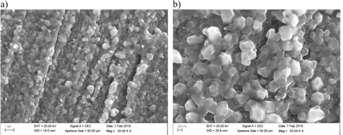
The structure of the films formed on the coupon specimens was found to change from thin (200-400 nm) porous single-layer film to a thick (10-30 µm) more compact, multi-layer film when the sulphide concentration in the solution increased. The two films are shown in Figure 21. These observations confirm that the sulphide concentration in the solution is an important factor influencing the structure and properties of the Cu2S film.
Three distinct types of Cu2S films have been reported in the literature, depending on the
sulphide concentration [10]. Type I: a thin single-layer, porous film observed at low sul-phide concentrations and low sulsul-phide fluxes; Type II: a porous, dual-layer film formed at intermediate and higher sulphide fluxes; and Type III: a passive or at least partially passive film formed at high sulphide concentrations and transport fluxes [10]. In this study, the low sulphide concentration produced a Type I film and the higher sulphide concentration pro-duced a Type II film according to this classification.
a) b)
Figure 21. a) Cross-section of thin crystalline Cu2S film on the Cu coupon after four weeks exposure in 0.00001 M Na2S solution at 90°C (coupon specimen 1W3_LS). b) Cross-sec-tion of thick crystalline Cu2S film on the Cu coupon after four weeks immersion in 0.001 M Na2S solution at 90°C (coupon specimen 1W3_HS).
3.3.1. High sulphide environment (exposure #8)
A compact film is formed at the high sulphide concentration. Once the Cu2S film covers
the Cu surface, corrosion proceeds with apparently constant rate by the growth of the film at the Cu2S/solution interface by Cu+ transportation through the film, most likely by diffu-sion along grain boundaries in the crystalline film. The film growth at the Cu2S/solution
interphase can account for the development of the well-defined large crystals of the Type II film. In this case, the Cu2S crystals are much larger (about 10-20 µm) than for Type I
films (about 200 nm). Figure 22 shows the Cu/Cu2S interface, cross-section of the film,
and roughness of the copper surface underneath the Cu2S film. Three distinct layers can be
distinguished in Figure 22 c) based on the grain size and shape. On the left, large columnar grains have grown from the copper surface, on top of this layer equiaxed fine grains have formed, and finally on top of this dual layer, the large plate-like grains have precipitated. The Cu/Cu2S interface showed no evidence of localized pitting corrosion. However, Figure
23 clearly shows that the copper surface is markedly roughened when the coherent Cu2S
grains have grown from the copper surface. Crystallographic marks have been left on the copper surface, which match exactly with the size of the crystals in the inner layer of the Cu2S film. Even though grain boundaries can be discerned from the Cu surface, no marked
intergranular corrosion has occurred in the unloaded coupon specimens. This is consistent with the presence of a uniformly distributed porous outer layer and confirms that localized anodic dissolution did not occur (no pitting locations or pitting at grain boundaries), in-cluding locations where large pores may have been present in the film.
a) b)
c) d)
Figure 22. a) Thick Cu2S film and the underlying corroded Cu surface in coupon specimen B2_ox_HS. b) Similar surface in coupon specimen B3_HS. c) Cross-section of a detached thick crystalline Cu2S film formed on coupon specimen 1W3_HS. d) Cross-section of Cu2S film formed on Cu surface of coupon specimen 1W1_ox_HS.
a) b)
Figure 23. Copper surface underneath the detached thick crystalline Cu2S film after four weeks exposure in 0.001 M Na2S solution at 90°C. Coupon specimens a) 2W1_ox_HS and b) B3_HS.
The growth of the coherent Cu2S film at the Cu/Cu2S interphase may be limited by the
build-up of an interfacial stress leading to film fracture. The Pilling-Bedworth (P-B) ratio for Cu2S on copper is 2, whereas the ratio for Cu2O on copper is 1.68. In general, if the
P-B ratio is greater than 1, compressive stresses form in the film, and if the ratio is greater than 2 the surface film is non-protective and may crack and flake off continuously exposing the metal surface [11]. Film growth at the film/solution interphase does not cause a build-up of interfacial stresses, and growth of the outer Cu2S layer can continue unimpeded at a
rate at least partially controlled by sulphide ion (SH-) diffusion to the film/solution inter-face. Most of the surface is covered with a relatively uniform deposit. Separation of the Cu2S film from the copper substrate confirms that the corroded copper surface is roughened
but not pitted. The corrosion damage is, however, non-uniform depending on the local crystal growth rates of the coherent Cu2S crystals of the inner film layer.
The outer film grows outwards by a mechanism controlled by a combination of Cu+ diffu-sion in the film and sulphide ion (SH-) diffusion in the solution. The film grows out from the copper surface in the form of flat plate-like crystals separated by some open spaces. The film growth process may also be partially controlled by a combination of SH- diffusion in the bulk solution and CuCl2- diffusion in the spaces between the Cu2S plates [12].
3.3.2. Low sulphide environment (exposure #9)
The corrosion film formed on the unloaded coupons in the low sulphide solution is shown in Figure 24. It is a continuous, single-layer cellular Cu2S film with a non-uniform
thick-ness of about 200-400 nm. The film consists of well-defined granular crystals of the same size in diameter as the film is in thickness. SEM images of openings in the film, shown in Figure 25, indicate that the Cu/Cu2S interphase shows very little corrosion attack when
compared to the high sulphide conditions. There are no indications of localized corrosion behaviour. The grinding marks are still visible on the copper surface.
Due to the roughness, brittleness, and porosity of the film, it is expected that the corrosion product film is not protective. The film growth process seems to be controlled by SH- dif-fusion partially in the bulk of the aqueous solution, as well as partially in the aqueous so-lution in the pores of the fine cellular Cu2S film.
a) b)
Figure 24. Thin crystalline Cu2S film on the Cu coupon surface after four weeks exposure in 0.00001 M Na2S solution at 90°C. Coupon specimens a) 1W1_ox_LS and b) 1W3_LS.
a) b)
Figure 25. Thin crystalline Cu2S film on the Cu coupon surface after four weeks exposure in 0.00001 M Na2S solution at 90°C. Coupon specimens a) 1W1_ox_LS and b) 1W4_LS.
3.3.3. Pre-oxidized specimens
Before exposure, some coupon specimens where pre-oxidized according to the procedure of [9] to study the conversion of Cu2O film on the copper surface to Cu2S film in aqueous
sulphide solutions. The compositions and morphologies of the oxide films were determined using SEM/EDS and XRD. The appearance of the oxide film before exposure to the sul-phide solution is shown in Figure 26.
After four weeks exposure in the high sulphide solution, the Cu2S film on the specimen
surface looks similar to the other specimens, and in general very few traces of the pre-oxidized film are preserved on the surface. Figure 27 shows the structure of a typical Cu2S
film formed on the pre-oxidized specimens after exposure to sulphide solution. When com-paring Figure 27 b) to Figure 22 c), which shows a non-pre-oxidized specimen, it can be seen that the inner Cu2S layer is very similar consisting of the columnar Cu2S crystals, but
the middle layer seems much more porous than in the non-pre-oxidized specimens. The outer precipitated plate-like large Cu2S crystals are again similar to the unloaded
non-pre-oxidized specimen. Locally under the detached Cu2S film, areas can be found where debris
of the pre-oxidized film are still preserved, as shown in Figure 28. EDS analyses of these debris show that they also contain some sulphur, indicating that they have reacted with the sulphide containing solution.
The Cu2S film formed on the pre-oxidized specimens in the low sulphide solution is thin
and contains much porosity, as shown in Figure 29. The shape of the grinding marks is often still visible on the film surface. The Cu2S crystals are also not as well distinguishable
as for the unloaded non-pre-oxidized specimens tested in the same environment. This may be seen, for example, by comparing Figure 25 b) and Figure 29 b), which have the same magnification. Under the film, the copper surface does not seem to be corroded markedly. The conversion of a Cu2O film on the copper surface to Cu2S in aqueous sulphide solutions
at both the higher and the lower concentration occurs quickly, and the conversion seems to be almost 100 % efficient. After four weeks exposure to sulphide solutions, the films on specimen surfaces are similar to the non-pre-oxidized specimens. The pre-existing oxide film does not seem to have any major effect on the Cu2S film forming process.
Figure 26. Pre-oxidized Cu surface before exposure to sulphide solution.
a) b)
Figure 27. Cross-sections of the Cu2S film formed on the pre-oxidized copper surface after four weeks exposure in 0.001 M Na2S solution at 90°C. a), b) Coupon specimen B1_ox_HS.
a) b)
Figure 28. Surface of pre-oxidized specimen under the thick Cu2S film, showing remnants of the oxide film preserved from the conversion process into Cu2S film. a), b) Coupon spec-imen B2_ox_HS.
a) b)
Figure 29. Porosity in the Cu2S film formed on the pre-oxidized specimen B2_ox_LS during four weeks exposure to 0.00001 M Na2S solution at 90°C.
3.3.4. Weld metal specimens
FSW weld metal specimens representing both welding in air, named 1W(n), and welding in Ar shielding gas, named 2W(n), where (n) represents the number of the specimen, were exposed in the test solutions simultaneously with the tensile specimen and the other coupon specimens. In general, the Cu2S film appearance is similar to the films formed on the base
material. However, weld metal specimens showed some interesting features that were not present in the base material. Figure 30 a) shows an opening in the Cu2S film, formed on the
air-welded specimen, revealing that the oxide stringers [13] in the weld metal were attacked and sulphidised under the Cu2S film. In Figures 30 b) and c), opening and depth of the
attacked oxide stringers in the weld metal may be seen. In the weld metal welded under shielding gas, no such corrosion attack was found in any of the specimens, and the copper surface under the Cu2S film was only roughened (with matching morphology to the Cu2S
crystals of the inner film), as shown in Figure 30 d). Thus, it can be concluded that also the Cu2O particles in the weld metal will be destabilized in the presence of dissolved sulphide
ions in the solution in addition to the pre-existing oxide film.
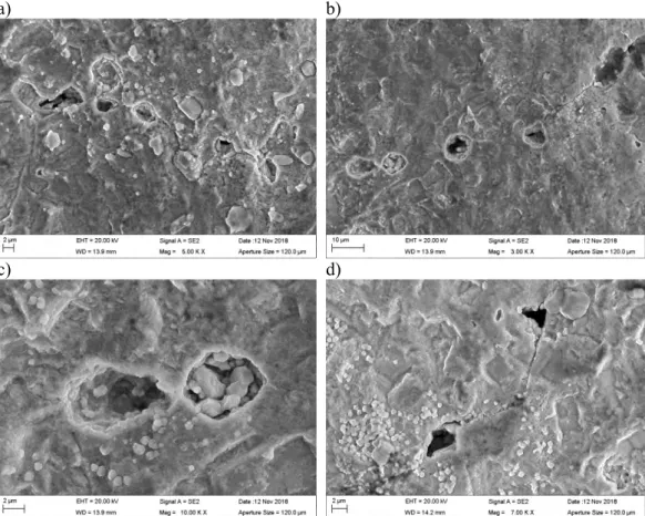
A common feature in both weld metal specimens, shown in Figure 31, was that the Cu2S
film was not continuous and there were openings revealing the Cu surface. In the middle of these openings, there was always a particle that had corroded. The particles were ana-lysed by EDS and their corrosion products always contained iron (Fe) and nickel (Ni) ox-ides and sulphox-ides. It can be concluded that these Fe/Ni rich particles most likely are debris of the tool wear, which were embedded in the weld metal during the welding process. Sometimes plenty of Fe rich corrosion products had formed filling the whole opening in the Cu2S film. This is shown in Figure 31 d).
In the low sulphide solution, very similar thin Cu2S film formed on the weld metal surfaces
as on the base material. However, typical for the weld metals was that the specimens showed small surface defects, shown in Figure 32 a), both in specimens welded in air and in the shielding gas, which are clearly visible on the surface in addition to the grinding marks. In pre-oxidized condition, the surface film was uneven and contained much poros-ity, visible as holes in the film in Figure 32 b). In the low sulphide conditions, corrosion attack on oxide stringers in the weld metal, welded in air, and on particles left from the tool wear, was not found, as in the specimens exposed to the high sulphide containing solution.
a) b)
c) d)
Figure 30. Surface morphology and cross-section of the Cu2S film, as well as attacked oxide particles on the Cu surface under the film after four weeks exposure in 0.001 M Na2S solution at 90°C. Coupon specimens a), b) and c) 1W1_ox_HS, and d) 2W1_ox_HS.
a) b)
c) d)
Figure 31. Openings in the Cu2S film on the weld specimens are related to Fe/Ni rich par-ticles embedded in the weld metal. The parpar-ticles were locally attacked during the four weeks exposure in 0.001 M Na2S solution at 90°C. Coupon specimens a) 1W1_ox_HS and b), c), d) 2W2_HS.
a) b)
Figure 32. Surface morphology of the Cu2S film and defects on the weld metal surface, as well as porosity of the film after four weeks exposure in 0.00001 M Na2S solution at 90°C. Coupon specimens a) 2W3_LS, and b) 2W1_ox_LS.
3.4. Results of hydrogen thermal desorption spectroscopy
(TDS)
Temperature dependencies of hydrogen desorption rates measured after SSRT in the high sulphide environment, and for the unloaded coupons exposed in the high sulphide environ-ment, are shown in Figures 33 and 34, respectively. The desorption curve for the as-sup-plied state is shown for comparison purposes. The graphs manifest a distinctive desorption peak of hydrogen in the temperature range of 550 to 850 K. The peaks consist of, at least, two overlapping components, which are more visible in the as-supplied state.
There are two significant findings of the TDS measurements. First, an increase of hydrogen content in all TDS samples cut from SSRT specimen #8, tested in 0.001 M sulphide envi-ronment, has occurred when compared to hydrogen content in the as-supplied state. Spec-imens S1_G1_HS and S1_G2_HS were cut from the gauge section, and specSpec-imens S1_S_HS and S1_L_HS were cut from the threaded ends of the tensile specimen (Figure 33). S1_G1_HS, which was cut from the narrow gauge-section, contains the most hydro-gen, possibly because it experienced the most deformation. The second finding concerns the hydrogen uptake in the unloaded FSW weld metal measured after exposure in the 0.001 M sulphide environment. As seen in Figure 34 a), the copper specimen welded in air (1W3_HS, green curve) manifests almost three times higher hydrogen content than the ma-terial welded in the protective atmosphere (2W3_HS, blue curve). This indicates that the copper oxide (Cu2O) particles, which form in the FSW process in the presence of oxygen
and are mixed in the bulk of copper, act as strong trapping sites for hydrogen. Moreover, a great number of hydrogen partial pressure spikes is observed on the low-temperature side of the TDS peak, evidencing that hydrogen forms gas-filled voids at the Cu2O particles,
some of which are located close to the specimen surface and open suddenly due to increas-ing gas pressure with increasincreas-ing temperature. Magnification of some of the spikes is shown Figure 34 b).
Figure 33. Temperature dependencies of hydrogen desorption rate for samples cut from tensile specimen #8 after SSRT in 0.001 M sulphide environment. Samples cut from the gauge section are named S1_G1_HS and S1_G2_HS. Samples cut from the threaded ends are named S1_S_HS and S1_L_HS. Unloaded copper coupon subjected to the same envi-ronment is named B2_ox_HS, and unexposed reference sample in as-supplied state is named B_AS1.
a) b)
Figure 34. a) Temperature dependencies of hydrogen desorption rate for samples cut from the unloaded coupons of FSW copper welded in air (1W3_HS) and in protective atmos-phere (2W3_HS), as well as for the base copper (B2_ox_HS) after exposure in 0.001 M sulphide environment. The reference samples in as-supplied state are named B_AS1 for the base material and 69_AS1 for the weld metal welded in air. b) Magnification of de-sorption spikes marked in a) with the red dashed box.
Figure 35 a) shows the hydrogen desorption curves of TDS samples cut from the SSRT specimen #9, and b) cut from the unloaded coupons of Cu-OFP tested in the same low sulphide environment. They manifest a rather different behaviour when compared to cop-per tested in the high sulphide environment. As expected, the exposure of copcop-per in the low sulphide environment results in reduced hydrogen uptake, which was not clear in the pre-vious short time testing of two weeks [3], but still hydrogen concentration in the samples cut from the SSRT specimen #9 after plastic deformation is higher than that of the unloaded coupons of the base material or argon shielded weld after exposure in the same environ-ment.
Comparison of Figure 35 b) and Figure 34 a) shows that hydrogen uptake in the unloaded copper coupons in 0.00001 M sulphide environment is markedly reduced when compared to exposure in the high sulphide environment. Note that the scale of hydrogen desorption rate is different in the two graphs. In the samples exposed to the low sulphide environment, no spikes were observed on the low temperature side of the TDS curves of FSW copper welded in air. However, hydrogen concentration in this sample (1W4_LS2) was still some-what higher than that in the coupon of the FSW copper welded with protective atmosphere (2W4_LS2).
a) b)
Figure 35.a) Temperature dependency of hydrogen desorption rate for samples cut from tensile specimen #9 after SSRT in 0.00001 M sulphide environment. Samples S07_LS, S08_LS and S10_LS were cut from the gauge section and samples S01_LS and S09_LS from the threaded ends. Unloaded base copper exposed in the same environment is marked with B4_LS2, and the reference sample in as-supplied state with Cu_Base (=B_AS1). b) Hydrogen desorption rate for samples cut from the unloaded coupons of base copper (B4_LS2) and FSW copper welded in air (1W4_LS2) and under shielding gas (2W4_LS2), measured after exposure in 0.00001 M sulphide environment, as well as for the reference sample in the as-supplied state.
It is important to notice that the hydrogen content in the unloaded copper coupons after exposure in the low sulphide environment is markedly reduced when compared to the as-supplied base material (see Figure 35 b). Such behaviour originates possibly from the fact that the autoclave tests were performed at an elevated temperature of 90°C. So-called met-allurgical hydrogen is always present in copper and it can diffuse out of the sample, if the low sulphide environment does not provide hydrogen with high enough fugacity. The low fugacity of hydrogen is evidenced by the absence of spikes in the TDS curve of the FWS sample welded in air and exposed in the low sulphide environment; hydrogen gas (H2) filled voids may form at the Cu2O particles only in the presence of hydrogen of high enough
fugacity. The hydrogen contents in the TDS samples cut from the SSRT specimen #9 were similar to the as-supplied state, but still higher than in the unloaded coupon specimens. This further indicates that plastic deformation enhances the hydrogen uptake in the SSRT spec-imen.
Finally, the copper Cu2S film was removed from the surface of one coupon specimen
ex-posed to the high sulphide environment and measured for hydrogen content. Figure 36 shows the partial pressures of hydrogen and water vapor in the Cu2S powder. It is seen, that
the powder contains hydrogen as a consequence of corrosion reactions of copper in the sulphide containing environment, as well as a small amount of water.
Figure 36. Temperature dependency of partial pressure of hydrogen (red curve) and water vapor (blue curve) in Cu2S powder detached from unloaded coupon of base copper after exposure in 0.001M sulphide environment.
For further analysis, the hydrogen contents of each specimen were calculated as area under the TDS curves, some of them shown in Figures 33-35. An overview of the hydrogen con-tents is shown visually in Figure 37 and numerically in Table 3. Coupons of base material are marked with B(n), coupons of FSW made in air are marked with 1W(n), and coupons of FSW produced in protective atmosphere are marked with 2W(n), where (n) represents the number of the coupon specimen, as several TDS samples were cut from some of the coupons. Samples cut from the SSRT specimens are marked with S(n).
Figure 37 visualizes the above conclusion, that in general the samples exposed at the higher sulphide level have a higher hydrogen content when compared to the samples exposed at the lower sulphide level. The mechanically loaded samples in both sulphide conditions show the highest hydrogen content in the narrow gauge section (1.08 wt.ppm in high sul-phide and 0.67 wt.ppm in low sulsul-phide conditions) compared to the wide gauge section (0.88 wt.ppm and 0.65 wt.ppm, respectively, for the high and low sulphide conditions) and the threaded sections showing the lowest values (0.84 wt.ppm and 0.62 wt.ppm, respec-tively). Although the differences in low sulphide conditions are within the limits of the measurement technique (0.02 wt.ppm), the high sulphide specimens seem to suggest that the hydrogen uptake is dependent on the level of deformation. However, the number of samples was limited, and the results should thus be viewed in the light of this.
It should be noted, that the highest hydrogen content of 1.58-2.05 wt.ppm was measured in the FSW weld metal welded in air and tested in the high sulphide environment. The hydro-gen content of the specimens welded in air is more than that in the mechanically loaded SSRT specimen tested in the same environment (0.83-1.08 wt.ppm). This may be explained by the oxide particles in the air welded copper functioning as hydrogen trapping sites and possibly reacting with the sulphide solution. Thus, the air welded copper is a special case. In general, the samples cut from the mechanically loaded specimens contained more hy-drogen than the unloaded base material coupon specimens tested in the same environment. In the high sulphide environment, the average hydrogen content of the unloaded coupons (excluding the air welded specimens due to the above-mentioned reason) is 0.77±0.11 wt.ppm, whereas in the SSRT specimen it is 0.91±0.09 wt.ppm. This difference is more evident in the low sulphide conditions as the coupon specimens (again excluding the air
welded specimens) contained on average 0.29±0.06 wt.ppm hydrogen, but the plastically deformed SSRT specimen contained on average 0.64±0.02 wt.ppm hydrogen. The hydro-gen content of the coupon specimens tested in the low sulphide environment was reduced from the initial base material state (which was 0.66 wt.ppm), but this may be explained by the outgassing due to the elevated temperature of 90°C and low fugacity of hydrogen in the low sulphide conditions. Still, the higher hydrogen content in the SSRT specimen, when compared to the mechanically unloaded coupons tested in the low sulphide environment, further indicates that plastic deformation of copper enhances the hydrogen uptake, resulting in these tests in similar hydrogen content in the SSRT specimen as in the as-supplied state. In the high sulphide conditions hydrogen absorption in the unloaded coupon specimens (excluding the air welded specimens) was negligible, except for specimen B3_HS, but on average plastic deformation still increased the hydrogen absorption in the high sulphide environment as well.
The exact trapping sites of hydrogen in copper are still unknown. However, the TDS peaks appear most likely due to hydrogen de-trapping from energetically deep trapping sites in the copper crystal lattice, such as vacancies and vacancy complexes. The obtained TDS results suggests that plastic deformation of Cu-OFP in the sulphide environment enhances the generation of not only the excessive hydrogen, but also the corresponding crystal lattice defects forming in plastic deformation. However, verification of the above hypothesis still needs additional studies.
Figure 37. Hydrogen contents of base materials, coupon specimens, and SSRT specimens tested in the two different sulphide environments at 90°C.
Table 3. Hydrogen contents measured with TDS from samples cut from the SSRT specimens
and from the coupon specimens, as well as from the as-supplied Cu-OFP lid material and as-welded FSW copper welded in air.
Sample Weight (g) Thickness (mm) Hydrogen content (at.ppm) Hydrogen content (wt.ppm)
B_AS1 (base material) 0.4333 0.890 41.86 0.66
69_AS1 (FSW in air) 0.3419 0.880 50.26 0.79 10-3 M Na 2S Coupon specimens B1_ox_HS* 0.2988 0.980 48.2 0.76 B2_ox_HS* 0.3031 0.980 46.6 0.73 B3_HS 0.2957 0.980 64.22 1.01 1W1_ox_HS* 0.2969 0.986 100.13 1.58 1W3_HS 0.3002 0.965 130.42 2.05 2W1_ox_HS* 0.2625 0.978 38.55 0.61 2W3_HS 0.3135 0.980 48.01 0.76
Cu2S powder** 0.0494 1.000 N/A N/A
10-3 M Na 2S SSRT specimen S1_L_HS 0.2846 0.904 53.38 0.84 S1_S_HS 0.2767 0.870 53.10 0.83 S1_G1_HS 0.3207 0.950 68.63 1.08 S1_G2_HS 0.3332 0.970 55.92 0.88 10-5 M Na 2S Coupon specimens B4_LS1 0.3190 0.970 10.35 0.16 B4_LS2 0.2982 0.960 15.78 0.25 B5_LS 0.2936 0.936 27.80 0.44 1W1_ox_LS* 0.2790 0.970 19.74 0.31 1W3_LS 0.2873 0.951 29.09 0.46 1W4_LS2 0.3074 0.947 19.16 0.30 2W1_ox_LS* 0.2933 0.960 14.20 0.22 2W3_LS1 0.3057 0.963 20.49 0.32 2W3_LS2 0.2919 0.955 19.74 0.31 2W4_LS1 0.3342 0.970 18.75 0.30 2W4_LS2 0.2942 0.990 14.00 0.22 10-5 M Na2S SSRT specimen S01_LS 0.3797 0.928 38.69 0.61 S10_LS 0.3657 0.936 42.86 0.67 S07_LS 0.3792 0.923 44.29 0.63 S08_LS 0.3791 0.924 41.63 0.66 S09_LS 0.3703 0.913 40.13 0.63
*Specimens pre-oxidized before the autoclave exposure;
**Amount of hydrogen in Cu2S powder was not calculated because of lack of calibration procedure
3.5. Sulphide and oxide film XRD characterization
The XRD diffractogram of the unexposed pre-oxidized specimen is shown in Figure 38. It confirms that the electrochemically deposited surface film on the specimen surface was a cuprite (Cu2O) film (see also Figure 26). No tenorite (CuO) was present in the film. Mainly
Cu peaks are visible because of the Cu substrate. The only oxide peak is the (111) Cu2O
peak. Note that the y-axis is in square root of the intensity. The amount of Cu2O here is
much below one atomic percent. The small peak at 39° 2 is the Kβ peak of the Cu(111) reflection. 25 30 35 40 45 50 55 60 65 Cu (200) Cu (111) sq rt( in ten si ty ) 2θ (°) Cu2O (111)
Figure 38. X-ray diffractogram of the pre-oxidized copper specimen B1_ox without expo-sure to the sulphide solution.
XRD measurements of three base material coupon specimens, two exposed in high sulphide environment (B3_HS and B2_ox_HS) and one exposed in low sulphide environment (B2_ox_LS) are shown in Figure 39. The peak locations coincide well for all the specimens, with the exception of copper substrate being clearly visible for the thin film formed on B2_ox_LS. There are large variations in intensities, though. This is probably due to the very large crystallites and non-random orientation of the crystallites, which leads to poor particle statistics. Major phase in all specimens appears to be monoclinic Cu2S (ICDD PDF card 33-490). All the reflections from specimen B3_HS can be explained by that phase. CuS does not seem to be present in any of the specimens. In comparison to the other spec-imens, there are noticeable reflections from residual Cu2O phase in the pre-oxidized B2_ox_HS specimen. These are marked with solid dots (ICDD PDF card 5-667). Some Cu2O is still left on the specimen surface from pre-oxidation before conversion of the oxide film to sulphide film (see also Figure 28). CuO was not found from the pre-oxidized spec-imen.