http://www.diva-portal.org
Postprint
This is the accepted version of a paper presented at 2017 IEEE 20th International
Conference on Intelligent Transportation Systems (ITSC), Kanagawa, Japan, 16-19
October, 2017.
Citation for the original published paper:
Aramrattana, M., Larsson, T., Englund, C., Jansson, J., Nåbo, A. (2017)
Simulation of Cut-In by Manually Driven Vehicles in Platooning Scenarios.
In: 2017 IEEE 20th International Conference on Intelligent Transportation Systems
(ITSC) (pp. 315-320).
N.B. When citing this work, cite the original published paper.
Permanent link to this version:
Simulation of Cut-In by Manually Driven Vehicles
in Platooning Scenarios
Maytheewat Aramrattana
∗,†, Tony Larsson
∗, Cristofer Englund
∗,‡, Jonas Jansson
†and Arne N˚abo
†∗School of Information Technology, Halmstad University, Halmstad, Sweden
Email:{maytheewat.aramrattana, tony.larsson}@hh.se
†The Swedish National Road and Transport Research Institute (VTI), Link¨oping, Sweden
Email:{jonas.jansson, arne.nabo}@vti.se
‡RISE Viktoria, Gothenburg, Sweden
Email: cristofer.englund@ri.se
Abstract—In the near future, Cooperative Intelligent Transport System (C-ITS) applications are expected to be deployed. To support this, simulation is often used to design and evaluate the applications during the early development phases. Simulations of C-ITS scenarios often assume a fleet of homogeneous vehicles within the transportation system. In contrast, once C-ITS is deployed, the traffic scenarios will consist of a mixture of connected and non-connected vehicles, which, in addition, can be driven manually or automatically. Such mixed cases are rarely analysed, especially those where manually driven vehicles are involved. Therefore, this paper presents a C-ITS simulation framework, which incorporates a manually driven car through a driving simulator interacting with a traffic simulator, and a communication simulator, which together enable modelling and analysis of C-ITS applications and scenarios. Furthermore, example usages in the scenarios, where a manually driven vehicle cut-in to a platoon of Cooperative Adaptive Cruise Control (CACC) equipped vehicles are presented.
I. INTRODUCTION
Cooperative Intelligent Transport Systems (C-ITS) is a strong trend in the development of the future transport systems, where the actors are equipped with wireless communication modules that enable them to communicate, interact, and co-operate. The overall goal with C-ITS is to improve safety, comfort, and efficiency [1]. The actors in C-ITS are vehicles and road infrastructure such as traffic lights, eventually it
can also include pedestrians and bicyclists in the future1.
Apart from connectivity, which is needed to achieve maximum benefits from the systems, different levels of automation and intelligent adaptivity of vehicles and infrastructure may also be part of C-ITS.
Modelling and simulation are often used to support de-sign and evaluation of C-ITS applications [2]–[5] including CACC/Platooning applications [6]–[10]. While combinations of traffic and network simulators are commonly used to study such applications [6], [8], [10], driving simulators are not common. Major reasons for this could be fewer available open source driving simulation software, compared to traffic and network simulators. And, most of the driving simulators are coupled with hardware which requires extra space and cost. Moreover, the main purpose of driving simulator studies is
1Only vehicles are studied in this paper.
focused on the driver, efforts are put on details of the ego vehicle and its driving behaviour, rather than studying a system of vehicles. However, driving simulators can offer realistic human driver behaviour and interaction, which is required in order to study the traffic scenarios with human drivers involved.
The main study cases of this paper are applications in the context of Cooperative Adaptive Cruise Control (CACC) and especially platooning. CACC and automated platooning has slightly different operational concepts depending on the inter-vehicle gap regulation strategy, as stated in [11]. However, in this paper the terms will be used interchangeably, referring to an application, that utilize vehicle-to-vehicle (V2V) communi-cation to maintain a stable platoon2 of vehicles. The goals of the application can include, e.g., to improve safety, maintain string stability3, reduce fuel consumption, and improve driver comfort. Most of the studies assume homogeneous traffic, where all vehicles are identical, connected, and automated. Even so, considering real traffic scenarios on public roads is not yet the case. In early deployment of C-ITS applications, heterogeneous traffic—where combinations of vehicles with different capabilities are involved in the system—are to be expected [12]. Such heterogeneous traffic scenarios are not often studied, especially the ones involving human driven vehicles.
In particular, this study focuses on scenarios when a man-ually driven vehicle intervene with a platoon while doing a cut-in manoeuvre, which frequently occurs in today’s traffic.
In relation to ACC4/CACC operations, a few studies have
con-sidered this type of scenario. V. Milan´es & S. E. Shladover [13] have presented effects of the cut-in and cut-out in long strings of CACC vehicles, with results from simulations and on-road experiments. Moreover, Annika F.L. Larsson, et al. [14] presented a study on reaction time of drivers in an ACC-equipped vehicle, when a cut-in happens.
Therefore, the contributions of this paper are twofold: 2In this paper, the term platoon is also refers to a string of vehicles that
are operating with the CACC function activated.
3The effects of distance error, or disturbances do not amplify as it
propagates backwards to the following vehicles in the platoon.
• We present a simulation framework with possibility to manually drive a vehicle in a C-ITS scenario.
• We show simulation results of the behaviour of two
different CACC controllers in a cut-in scenario using the simulation framework.
The remainder of the paper is organized as follows. Sec-tion II introduces a C-ITS simulaSec-tion framework with possi-bility to involve a manually driven car in C-ITS scenarios. This section also presents challenges, and results from including a human driver in the simulation framework. Section III defines the cut-in scenario, and parameters related to the CACC controllers and the simulation study. Section IV presents results from the scenario, where the manually driven car cut-in between vehicles in the platoon. Future work is presented in Section V. Finally, the paper is concluded in Section VI
II. THEC-ITS SIMULATIONFRAMEWORK
A. Background
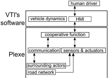
The C-ITS simulation framework consists of driving-, traffic-, and network simulators. The driving simulator is executed by the driving simulation software from the Swedish National Road and Transport Research Institute (VTI). And Plexe [6]—Platooning Extension for Veins—is used for traffic and network simulation. The software structure and included simulation models are illustrated in Fig. 1.
Plexe
road network surrounding actors
sensors & actuators communication human driver HMI cooperative function vehicle dynamics
VTI's
software
Fig. 1: Simulation models that are considered in the C-ITS simulation framework.
VTI’s driving simulation software is developed in-house at VTI. It is implemented in C++, and the same software kernel can be run on a desktop computer, or the computer-controlled moving-base driving simulators at VTI [15]. Plexe is developed based on the microscopic traffic simulator, SUMO (Simulation of Urban Mobility) [16], and the network simulator, Veins [17]. Plexe extends both SUMO and Veins to support more realistic simulation of platooning scenarios, by considering vehicle dynamics in the form of actuation lag (modelled by a low pass filter), and the V2V communication protocol stack used to send messages according to the IEEE 802.11p standard. OMNeT++ MiXiM Veins plexe-sumo SUMO plexe-veins TraCI VTI's driving simulator
Fig. 2: The TCP connections between simulation software in the C-ITS simulation framework.
As illustrated in Fig. 2, the different simulation software used in the framework are connected via three transmission control protocol (TCP) connections: a) TraCI (traffic control interface), an existing connection for SUMO and Veins to in-teract according to [18]; b)T CPsyncfacilitating
synchroniza-tion between the driving simulator and Plexe; and c)T CPapp
for exchanging information between the driving simulator and Plexe. Please refer to our previous work [19], [20] for more details.
The C-ITS simulation framework has been presented in [19], [20]. The framework is developed to support testing and evaluation of platooning applications, with a human driver in the loop. Previously, the human driver was included just as an operator or observer of the fully-automated platooning scenarios. By extending the existing framework, the human driver can now be more involved by driving a vehicle in the simulation framework. This development enables analysis of more complex platooning scenarios which are not commonly studied. For example, cut-in by non-V2V-equipped vehicles in platooning scenarios [13].
B. Involving a Human Driver
In driving simulators, it is common that the driver has freedom to drive anywhere in the simulated environment, this is one of the main features of every driving simulator. In contrast, the traffic simulation represents vehicles as al-ways driving in the middle of their lane. The only lateral movement modelled in the traffic simulation is the lane-changing behaviour, which occurs instantaneously within one time step. Driving behaviour is usually restricted in most of the microscopic traffic simulators. For instance, behaviour of each vehicle in SUMO is mainly controlled by a car-following and a lane-changing models.
Car-following models in microscopic traffic simulations are usually defined by ordinary differential equations. In SUMO, the “active” car-following model can be changed during the simulation. However, at one simulation time point, only one model can be active for a vehicle. The car-following model regulates longitudinal velocity of vehicle(s), by taking into account parameters such as distance to the preceding vehicle, current acceleration of the ego vehicle, maximum acceleration, etc. These parameters are different for each car-following model.
By default, car-following models in SUMO are collision free. In other words, the car-following models considers the distance to the preceding vehicle, and determined a “safe
speed”. Even when a command is sent to control the speed of the vehicle, the car-following model has priority to override it, if that speed is higher than the safe speed. Because the main purpose of traffic simulators has been to study traffic flow behaviour rather than hazard or traffic safety issues.
There is no such restriction in car-following models pro-posed by the Plexe framework, thus enabling the vehicles to drive closely in a platoon. Thus, to overcome this restriction, the Cruise Control car following model presented in [6] is modified to be used in this paper. Alternatively, the simulation parameters in SUMO can be set to ignore this safety check. The same problem arises for changing lane in SUMO. The vehicle will refuse to change lane if the space is not perceived as large enough for the lane-changing model. This has been solved as presented in [20]. 0 1000 2000 3000 4000 5000 6000 7000 time steps -2 0 2 4 6 lateral position (m)
From logged data from VTI From Plexe
Lane markings
Fig. 3: Lateral positions of the manually driven vehicle within the simulation framework.
To facilitate manual driving in the simulation, information about longitudinal speed and current lane of the ego vehicle
are sent from the driving simulator to Plexe via the T CPapp
connection (as illustrated in Fig. 2). The simulation framework run at 0.01 second time step (100 Hz). Figure 3 shows plots of the logged lateral positions at each time step from Plexe and the driving simulator. The information about the ego vehicle’s current lane comes from the driving simulation software. There, the lane change occurs when the front axle of the ego vehicle crosses the lane marking in the driving simulator. However, in Plexe, the lane change is instantaneous as depicted by the red dashed plot in Fig. 3.
III. THECUT-IN
A cut-in scenario by a manually driven vehicle is achieved using the simulation framework presented in the previous section. The cut-in scenario is simulated on a two-lane straight highway. As illustrated in Fig. 4, four vehicles are simulated, three cars that are operated by a CACC function (the vehicle no. 1, 2, and 3 in Fig. 4) driving on the right lane, and one manually driven car (the vehicle no. 4 in Fig. 4) on the left lane. During the simulation, the driver of the manually driven car (no. 4) performs a cut-in manoeuvre, merging and placing the car in front of the second vehicle in the platoon (as shown in Fig. 4). Further, it is assumed that the manually driven car does not have automated driving capability, but may have an ability to transmit V2V communication messages such
as to communicate its intention, or broadcasting Cooperative
Awareness Messages (CAMs). Table I lists the configuration that the manually driven vehicle may have. In this paper, only one configuration marked by ‘⋆’ in Table I is studied. That is the cut-in scenario by a manually driven vehicle without V2V communication (non-communicating vehicle).
3 2 1
4
Fig. 4: The manual cut-in scenario. The vehicle no. 4 is driven by a human driver, the other cars are operated by the
CACC function in the simulator.
TABLE I: Possible configurations for the human-driven car. The ‘⋆’ indicates the one that considered in this paper.
Sharing Intention
Sending CAM Yes No
Yes
No ⋆
The following two existing CACC controllers in Plexe are used for the platooning vehicles, namely:
• Rajamaniis the constant-distance gap controller, which
is implemented by the author of Plexe following the book by Rajamani [21, Chapter 7]
• Ploeg is the constant-time gap controller, which is
im-plemented by the author of Plexe following the work by
Ploeg et al.[22]
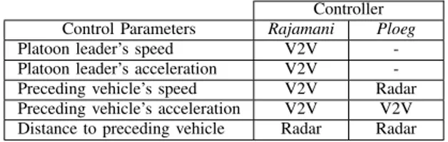
Apart from the different control strategies, there are a few more differences between these two controllers. The Rajamani controller uses information about the speed and acceleration of the platoon leader as control parameters, while the Ploeg controller only uses information about the preceding vehicle. Moreover, the Rajamani controller obtains the speed of the preceding vehicle from the V2V communication, while the
Ploeg controller obtains the information from the radar. The differences are summarized in Table II. Nevertheless, during the operation of both CACC controllers in our simulation, each follower receives the information about speed, acceleration, and position of the platoon leader and its preceding vehicle via V2V communication. A desired inter-vehicle distance of 17.5 meters (0.6 second headway time) was chosen for the CACC controllers. All vehicles are equipped with radar that detects an object in front. If there is no such object, nothing is detected and the radar returns -1 as output. As mentioned in Section II-B, the lane change in Plexe happens instantaneously, when the front axle of the vehicle in the driving simulator crosses the lane marking (see Fig. 3). Therefore, in this paper the radar is assumed to have a relatively wide angle covering the driving lane, i.e. it will detect the cut-in vehicle as soon as the cut-in vehicle’s front axle cross the lane marking.
TABLE II: List of the information used by the two CACC controllers and their source.
Controller Control Parameters Rajamani Ploeg
Platoon leader’s speed V2V -Platoon leader’s acceleration V2V -Preceding vehicle’s speed V2V Radar Preceding vehicle’s acceleration V2V V2V Distance to preceding vehicle Radar Radar
IV. RESULTS
In this section, vehicle no. 4 in Fig. 4 will be referred to as the “manually driven car”, and the platooning vehicles no. 1, 2, and 3 will be referred to as the platoon leader, second
vehicle, and last vehicle respectively, as illustrated in Fig. 4.
A. Conventional Car Cut-In
The results of the cut-in scenario using two CACC con-trollers with desired inter-vehicle gap of 17.5 meters (0.6 second time headway) are presented in this subsection. At the steady-state, the platoon leader is always driving with constant speed of 90 km/h (25 m/s). Since the platoon leader is not affected by the cut-in manoeuvre it is excluded from all the plots in this subsection.
40 50 60 70 80 90 100 110 time (s) 0 10 20 30
gap to the preceding car (m)
The manually driven car (no. 4) Platooning car no. 2 Platooning car no. 3
(a) Plots of the distances measured by radar to the object in front. 40 50 60 70 80 90 100 110 time (s) 15 20 25 30 35 speed (m/s)
The manually driven car (no. 4) Platooning car no. 2 Platooning car no. 3
(b) Plots of each vehicle’s speed.
Fig. 5: Results from the cut-in scenario using Rajamani controller with desired gap of 17.5 m.
Figure 5 shows the behaviour of the Rajamani controller, when the manually driven car cut into the platoon. Figure 5a depicts measurements from the radar in each of the vehicles. The cut-in occurs at approximately 61 second simulation time, where the measurements from radar change instantaneously
for the manually driven car and the second vehicle. The inter-vehicle distance is reduced to 6.35 meters for the second vehicle. Consequently, the second vehicle adjust its speed, and is able to prevent a collision. At approximately 85 seconds, the manually driven car leave the platoon giving a big gap in front of the second vehicle. Thus, it speeds up to close the gap and maintains a stable platoon. One can observe that the controller is string stable by looking at the behaviour of the last vehicle (platooning car no. 3), which does not amplify the error caused by the second vehicle.
40 50 60 70 80 90 100 110 time (s) 0 10 20 30
gap to the preceding car (m)
The manually driven car (no. 4) Platooning car no. 2 Platooning car no. 3
(a) Plots of the distances measured by radar to the object in front. 40 50 60 70 80 90 100 110 time (s) 15 20 25 30
speed (m/s) The manually driven car (no. 4) Platooning car no. 2 Platooning car no. 3
(b) Plots of each vehicle’s speed.
Fig. 6: Results from the cut-in scenario using Ploeg controller with desired gap of 0.6 second headway time. For the Ploeg controller, its behaviour during the cut-in scenario is presented in Fig. 6. In this case, the cut-in occurs at approximately 52 seconds simulation time, and the inter-vehicle distance is reduced to 6.75 meters for the second vehicle. Consequently, the second vehicle adjusts its speed, and is also able to prevent a collision. The manually driven car then leave the platoon at approximately 86 seconds. Again, the string stability of the controller can be observed.
B. Collision
Plots in Fig. 7 presents a collision, when the manually driven car cut into a platoon operated by the Rajamni controller at 17.5 meters vehicle distance. Even though the inter-vehicle gap at the cut-in point (≈ 61 seconds time) is 9.76 meters, which is higher than that of the same scenario above, the large difference in speed causes the collision (see Fig 7b at 63 seconds).
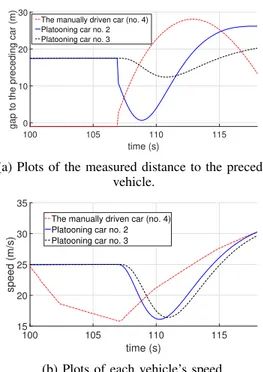
On the other hand, the Ploeg controller was able to handle the situation, when the cut-in vehicle has a difference in speed, as shown in Fig. 8 (at 107 seconds simulation time).
40 45 50 55 60 65 time (s) 0 5 10 15 20 25
gap to the preceding car (m)
The manually driven car (no. 4) Platooning car no. 2 Platooning car no. 3
(a) Plots of the measured distance to the preceding vehicle. 40 45 50 55 60 65 time (s) 0 10 20 30 speed (m/s)
The manually driven car (no. 4) Platooning car no. 2 Platooning car no. 3
(b) Plots of each vehicle’s speed.
Fig. 7: Results from the cut-in scenario, when a collision occurs after the cut-in. Platooning vehicles are using
Rajamani controller with desired gap of 17.5 m.
Nevertheless, it requires the second vehicle to apply maximum deceleration of 4.5 m/s2, in order to prevent a collision. The maximum deceleration is considered as an emergency braking manoeuvre, according to [23]. Furthermore, this hard-braking manoeuvre could be dangerous to the vehicles behind the platoon, and might result in a rear-end collision.
Furthermore, we simulated a similar situation with the same speed difference, but with a desired inter-vehicle gap of 30 meters. The Rajamani controller is then able to handle the situation and prevent the collision. However, the collision still occurs when the platoon leader speeds up, because the controller’s dependency to the platoon leader’s speed and acceleration. The platooning vehicles speed up to follow the platoon leader, and collide into the manually driven car. Hence, to prevent a collision, switching the active controller to ACC when a cut-in is detected by non-communicating vehicles, as suggested in [13] is required. Also, the vehicle that the manually driven car merged in front of have to be assigned as the new platoon leader for each platooning vehicle behind it. In contrast, the Ploeg controller reacts differently to the platoon leader speeding up, the collision did not happen in this case. Because most of the controller’s decision is based on the information from the radar, which detects the manually driven car. Although the collision did not happen in our simulation, it is still possible under certain amount of leader’s acceleration, and other parameter settings than the ones used in this simulation. Therefore, even though the Ploeg controller behave similarly to ACC, i.e. using radar to detects inter-vehicle gap and relative speed, switching to conventional ACC
100 105 110 115 time (s) 0 10 20 30
gap to the preceding car (m)
The manually driven car (no. 4) Platooning car no. 2 Platooning car no. 3
(a) Plots of the measured distance to the preceding vehicle. 100 105 110 115 time (s) 15 20 25 30 35 speed (m/s)
The manually driven car (no. 4) Platooning car no. 2 Platooning car no. 3
(b) Plots of each vehicle’s speed.
Fig. 8: Results from the cut-in scenario using the Ploeg controller with a desired gap of 0.6 second headway time.
when the cut-in is detected is preferable. V. FUTUREWORK
Many aspects of cut-in scenarios are still to be explored as follows. First, having cut-in manoeuvres with such large speed difference on a highway is not common, however not impossible. The results in Section IV-B show that the different designs of CACC controller may achieve similar efficiency in terms of string stability, but it can have different effects on the safety of the driver. Therefore, in the evaluation of the CACC controller design, safety should also be considered, in addition to string stability. Further investigation on a hazard and risk analysis framework for evaluation of safety-related issues is required.
Detecting the cut-in by a non-communicating vehicle is a challenge in itself. Observing a sudden change in distance measured by the radar as shown in the scenario above is one way to detect the cut-in event. The platooning vehicles may, as a complement, be equipped with a camera system, or other sensors such as LiDAR. Then, sensor fusion algorithms can be applied to better detect, or even predict the cut-in manoeuvre. Furthermore, considering future scenarios when conventional vehicles are equipped with V2V communication modules. They can still be driven manually, but have a possibility to broadcast CAM. In addition, intentions to cut-in, or change lane, can be broadcast. Although the standard CAM does not include the intention of the vehicle, this has been proposed in the i-GAME Cooperative Lane Change Message (iCLCM) in the Grand Cooperative Driving Challenge 2016 [1]. To fully utilize the intention message, extension on the platooning application with a strategy to handle the message is required.
Moreover, the more common cut-in events are perhaps the ones happening at the on-ramps to highways, which is more time-critical due to the limited space in the acceleration lanes. Using V2V communication to communicate the intention as discussed above could be necessary to facilitate the cut-in, especially for long platoons. If we were to facilitate such cut-in, many questions need to be answered. For instance, How
should the platoon react to the intention message? Should the platoon make a gap to support the cut-in, how big gap will the human drivers accept? The proposed C-ITS simulation framework has potential to be used as a tool to study such questions.
Last but not least, the behaviour of the manually driven car varies between different simulation runs and drivers, but the scenarios are fixed in this paper, i.e. the manually driven car always cut-in between the first and second vehicle in the platoon. Hence, other realistic traffic scenarios must also be considered, e.g. cut-in at different parts of a platoon, different time headway settings, etc. Moreover, using this simulation framework, human drivers’ behaviour can be gathered to create a car-following model that includes the cut-in behaviour (as also desired in [13]).
VI. CONCLUSIONS
This paper presents the recent development of a C-ITS sim-ulation framework consisting of driving-, traffic-, and network simulators. The development allows human drivers to drive in the C-ITS simulation framework, which was not previously possible. Allowing manually driven vehicles by human drivers in a C-ITS simulation enables vast future studies related to C-ITS applications that involve human drivers. One of such applications include studying the cut-in scenario by a manually driven vehicle in a platooning application as presented in this paper. Preliminary results on a collision case study suggest that a radar-based CACC controller showed promising performance compared to a V2V-based controller with respect to collision avoidance. Safety issues and future works related to the cut-in scenario are presented and discussed as the results.
ACKNOWLEDGMENT
The authors would like to thank Jonas Andersson Hultgren at VTI for his guidance and support on the driving simulation software. Also, Michele Segata from the University of Trento (Italy), for his valuable advices regarding modification and details of Plexe.
REFERENCES
[1] C. Englund, L. Chen, J. Ploeg, E. Semsar-Kazerooni, A. Voronov, H. Hoang Bengtsson, and J. Didoff, “The Grand Cooperative Driving Challenge (GCDC) 2016 - boosting the introduction of Cooperative Automated Vehicles,” IEEE Wireless Communication Magazine, no. August 2016 Issue, 2016.
[2] F. J. Ros, J. A. Martinez, and P. M. Ruiz, “A survey on modeling and simulation of vehicular networks: Communications, mobility, and tools ,” Computer Communications, vol. 43, pp. 1 – 15, 2014.
[3] C. Englund, L. Chen, and A. Voronov, “Cooperative speed harmonization for efficient road utilization,” in 2014 7th International Workshop on
Communication Technologies for Vehicles, Nets4Cars-Fall 2014, 2014, pp. 19–23.
[4] Y. Zhao, A. Wagh, Y. Hou, K. Hulme, C. Qiao, and A. W. Sadek, “Integrated traffic-driving-networking simulator for the design of con-nected vehicle applications: eco-signal case study,” Journal of Intelligent
Transportation Systems, pp. 1–13, 2014.
[5] M. Gu´eriau, R. Billot, N.-E. E. Faouzi, J. Monteil, F. Armetta, and S. Hassas, “How to assess the benefits of connected vehicles? A simulation framework for the design of cooperative traffic management strategies ,” Transportation Research Part C: Emerging Technologies, vol. 67, pp. 266 – 279, 2016.
[6] M. Segata, S. Joerer, B. Bloessl, C. Sommer, F. Dressler, and R. L. Cigno, “Plexe: A platooning extension for Veins,” in 2014 IEEE
Vehic-ular Networking Conference (VNC), Dec 2014, pp. 53–60.
[7] J. Larson, K. Y. Liang, and K. H. Johansson, “A Distributed Framework for Coordinated Heavy-Duty Vehicle Platooning,” IEEE Transactions
on Intelligent Transportation Systems, vol. 16, no. 1, pp. 419–429, Feb 2015.
[8] D. Jia and D. Ngoduy, “Platoon based cooperative driving model with consideration of realistic inter-vehicle communication,” Transportation
Research Part C: Emerging Technologies, vol. 68, pp. 245 – 264, 2016. [9] L. Zhao and J. Sun, “Simulation Framework for Vehicle Platooning and Car-following Behaviors Under Connected-vehicle Environment,”
Procedia - Social and Behavioral Sciences, vol. 96, pp. 914 – 924, 2013.
[10] D. Jia, K. Lu, J. Wang, X. Zhang, and X. Shen, “A Survey on Platoon-Based Vehicular Cyber-Physical Systems,” IEEE Communications
Sur-veys Tutorials, vol. 18, no. 1, pp. 263–284, Firstquarter 2016. [11] S. E. Shladover, C. Nowakowski, X.-Y. Lu, and R. Ferlis,
“Cooper-ative Adaptive Cruise Control: Definitions and Operating Concepts,”
Transportation Research Record: Journal of the Transportation Research Board, no. 2489, pp. 145–152, 2015.
[12] M. Aramrattana, T. Larsson, and C. Jansson, Jonas Englund, “Di-mensions of Cooperative Driving, ITS and Automation,” in Intelligent
Vehicles Symposium (IV). Seoul: IEEE, 2015.
[13] V. Milan´es and S. E. Shladover, “Handling Cut-In Vehicles in Strings of Cooperative Adaptive Cruise Control Vehicles,” Journal of Intelligent
Transportation Systems, vol. 20, no. 2, pp. 178–191, 2016.
[14] A. F. Larsson, K. Kircher, and J. A. Hultgren, “Learning from expe-rience: Familiarity with ACC and responding to a cut-in situation in automated driving,” Transportation Research Part F: Traffic Psychology
and Behaviour, vol. 27, Part B, pp. 229 – 237, 2014, vehicle Automation and Driver Behaviour.
[15] J. Jansson, J. Sandin, B. Augusto, M. Fischer, B. Blissing, and L. K¨allgren, “Design and performance of the VTI Sim IV,” in Driving
Simulation Conference, 2014.
[16] D. Krajzewicz, J. Erdmann, M. Behrisch, and L. Bieker, “Recent Devel-opment and Applications of SUMO - Simulation of Urban MObility,”
International Journal On Advances in Systems and Measurements, vol. 5, no. 3&4, pp. 128–138, December 2012.
[17] C. Sommer, R. German, and F. Dressler, “Bidirectionally Coupled Network and Road Traffic Simulation for Improved IVC Analysis,” IEEE
Transactions on Mobile Computing, vol. 10, no. 1, pp. 3–15, January 2011.
[18] A. Wegener, M. Pi´orkowski, M. Raya, H. Hellbr¨uck, S. Fischer, and J.-P. Hubaux, “TraCI: An Interface for Coupling Road Traffic and Network Simulators,” in Proceedings of the 11th Communications and
Networking Simulation Symposium, ser. CNS ’08. New York, NY, USA: ACM, 2008, pp. 155–163.
[19] M. Aramrattana, T. Larsson, J. Jansson, and A. N˚abo, “Extended Driving Simulator for Evaluation of Cooperative Intelligent Transport Systems,” in Proceedings of the 2016 Annual ACM Conference on
SIGSIM Principles of Advanced Discrete Simulation, ser. SIGSIM-PADS ’16. New York, NY, USA: ACM, 2016, pp. 255–258.
[20] ——, “Cooperative Driving Simulation,” The Driving Simulation
Con-ference 2016 VR, 2016.
[21] R. Rajamani, Vehicle dynamics and control, 2nd ed. Springer US, 2012. [22] J. Ploeg, B. T. M. Scheepers, E. van Nunen, N. van de Wouw, and H. Nijmeijer, “Design and experimental evaluation of cooperative adaptive cruise control,” in 2011 14th International IEEE Conference
on Intelligent Transportation Systems (ITSC), Oct 2011, pp. 260–265. [23] European Commission, “COMMISSION REGULATION (EU) No
347/2012 of 16 April 2012 implementing Regulation (EC) No 661/2009 of the European Parliament and of the Council with respect to type-approval requirements for certain categories of motor vehicles with regard to advanced emergency braking systems,” 2012.