MALMÖ UNIVERSIT Y HEAL TH AND SOCIET Y DOCT OR AL DISSERT A TION 20 1 8:3 ELEN A GONZÁLEZ ARRIB AS MALMÖ UNIVERSIT FLEXIBLE AND TR ANSP ARENT BIOL OGIC AL ELECTRIC PO WER SOUR CES B ASED ON N AN OS TRUCTURED ELECTR ODES
Elena González Arribas
Flexible and transparent biological
electric power sources based on
nanostructured electrodes
F L E X I B L E A N D T R A N S P A R E N T B I O L O G I C A L E L E C T R I C
P O W E R S O U R C E S B A S E D O N N A N O S T R U C T U R E D
E L E C T R O D E S
Malmö University
Health and Society, Doctoral Dissertation 2018:3
© Copyright Elena González Arribas 2018
Front cover illustration: “In the eye” by Amanda Paniagua Liarte
ISBN 978-91-7104-828-8 (print)
ISBN 978-91-7104-829-5 (pdf)
ISSN 1653-5383
Elena González Arribas
Flexible and transparent biological
electric power sources based on
nanostructured electrodes
Malmö University, 2018
Faculty of Health and Society
Department of Biomedical Science
To my family and in memory of my grandfather, Benito González López Para mi familia y en memoria de mi abuelo, Benito González López
“Y quizá hayas andado el camino ya, cuando mires atrás. Si estás atrapado en las
sombras, aguarda, aguarda. Del lodo crecen las flores más altas.”
Lodo
, una canción de Xoel López“And maybe you've already walked the path, when you look back. If you are stuck in
the shadows, hang on, hang on. The highest flowers grow from the mud. “
CONTENTS
LIST OF PUBLICATIONS AND CONTRIBUTION ... 9
ABBREVIATIONS ... 12
ABSTRACT ... 14
POPULÄRVETENSKAPLIG SAMMANFATTNING ... 15
BIOENERGY ... 17
THESIS AT GLANCE ... 18
BIOLOGICAL ELECTRIC POWER SOURCES ... 20
Classification based on biocatalyst ... 20
Biocatalysts ... 23
Oxidoreductases ... 23
Organelles ... 29
Immobilisation of biocatalysts ... 30
Classification based on operational principle ... 33
Biofuel cells ... 33
Biosupercapacitors ... 36
EXPERIMENTAL METHODS ... 42
Microscopy ... 42
Atomic force microscopy ... 42
Scanning electron microscopy ... 43
Spectral methods ... 44
Ultraviolet-visible spectrophotometry ... 44
Electrochemical methods ... 45
Electrochemical potential ... 45
Standard potential ... 46
Formal potential ... 46
Devices to study electrode reactions and to test electrochemical systems ... 48
Two-electrode systems ... 49
Three-electrode systems ... 49
Electrochemical techniques ... 51
Voltammetry ... 51
Amperometry ... 52
Potentiometry ... 53
RESULTS AND DISCUSSION ... 54
Summary of the research papers ... 54
OUTLOOK ... 57
ACKNOWLEDGMENTS ... 62
REFERENCES ... 67
LIST OF PUBLICATIONS AND
CONTRIBUTION
Paper I:
E. González-Arribas, D. Pankratov, S. Gounel, N. Mano, Z. Blum, S.
Shleev, Transparent and capacitive bioanode based on specifically
engineered glucose oxidase. Electroanalysis, 23 (2016) 1290-1297.
• Contribution to paper I:
Took part in the designing of experiments and performed all
experimental part, except SEM imaging. Participated in the data
processing, writing of the experimental part of the paper and prepared
all graphic materials.
Review I:
D. Pankratov, E. González-Arribas, Z. Blum, S. Shleev, Tear based
bioelectronics. Electroanalysis, 28 (2016) 1250-1266.
• Contribution to review I:
Performed a literature overview and took a large part in writing of the
Chapter 4.
Paper II:
E. González-Arribas, T. Bobrowski, C. Di Bari, K. Sliozberg, R.
Ludwig, M. D. Toscano, A. L. De Lacey, M. Pita, W. Schuhmann, S.
Shleev, Transparent, mediator- and membrane-free enzymatic fuel cell
based on nanostructured chemically modified indium tin oxide
electrodes. Biosensors and Bioelectronics, 97 (2017) 46-52.
• Contribution to paper II:
Took part in designing of experiments, performed some experiments.
Participated in the evaluation of results, writing of the manuscript, and
prepared graphic materials.
Review II:
S. Shleev, E. González-Arribas, M. Falk. Biosupercapacitors. Current
Opinion in Electrochemistry, 5 (2017) 226-233.
• Contribution to review II:
Performed a literature review, helped with some graphic materials and
took a small part in writing of the manuscript.
Paper III:
T. Bobrowski, E. González-Arribas, R. Ludwig, M. D. Toscano, S.
Shleev, W. Schuhmann, Rechargeable, flexible and mediator-free
biosupercapacitor based on transparent ITO nanoparticle modified
electrodes acting in
µM glucose containing buffers. Biosensors and
Bioelectronics, 101 (2018) 84-89.
• Contribution to paper III:
Took part in designing of experiments and performed a significant part
of the experimental work. Participated in the evaluation of results and
preparation of graphic materials.
Paper IV:
E. González-Arribas, O. Aleksejeva, T. Bobrowski, M. D. Toscano, L.
Gorton, W. Schuhmann, S. Shleev. Solar biosupercapacitor, 74 (2017)
9-13.
• Contribution to paper IV:
Took part in designing of experiments and performed a significant part
of the experimental work, viz. fabricated and characterised biocathodes
and the complete biodevice. Participated in the evaluation of results,
writing of the manuscript and prepared some graphic materials.
Other publications not included in this thesis:
1. D. Pankratov, R. Sundberg, J. Sotres, I. Maximov, M. Graczyk, D.B.
Suyatin, E. González-Arribas, A. Lipkin, L. Montelius, S. Shleev.
Transparent
and
flexible,
nanostructured
and
mediatorless
glucose/oxygen enzymatic fuel cells. Journal of Power Sources, 294
(2015) 501-506.
2. Y.M. Parunova, S.O. Bushnev, E. Gonzalez-Arribas, P. Falkman,
A.V. Lipkin, V.O. Popov, S. Shleev, D. Pankratov. Potentially
implantable biocathode with charge-storing function based on
nanocomposite polyaniline/carbon nanotubes. Russian Journal of
Electrochemistry, 52 (2016) 1166-1171.
3. D. Pankratov, E. González-Arribas, Y.M. Parunova, M.A.
Gorbacheva, Y.S. Zeyfman, S.V. Kuznetsov, A. Lipkin, S.Shleev. New
nanobiocomposite materials for bioelectronics devices. Acta Naturae,
24 (2015) 98-101.
ABBREVIATIONS
AFM
atomic force microscopy
An
Aspergillus niger
APTES
(3-aminopropyl)triethoxysilane
BFC
biofuel cell
BOx
bilirubin oxidase
BSC
biosupercapacitor
C
acapacitance density
CDh
cellobiose dehydrogenase
CE
counter electrode
Ct
Corynascus thermophilus
CV
cyclic voltammetry
CYT
cytochrome
DET
direct electron transfer
Dh
dehydrogenase
EDC
1-ethyl-3-(3-dimethylaminopropyl)carbodiimide
EDL
electric double layer
EDLC
electric double layer capacitor
EFC
enzymatic fuel cell
ET
electron transfer
FAD
flavin adenine dinucleotide
GDh
glucose dehydrogenase
GLYMO
(3-glycidyloxypropyl)trimethoxysilane
GOx
glucose oxidase
IET
intramolecular electron transfer
ITO
indium tin oxide
LMPO
2lytic polysaccharide monooxygenase
LSV
linear sweep voltammetry
MCO
multicopper oxidase
MET
mediated electron transfer
Mt
Myrothecium verrucaria
MWCNT
multi-walled carbon nano-tubes
NHS
N-Hydroxysuccinimide
NP
nanoparticle
OCP
open circuit potential
OCV
open circuit voltage
Pa
Penicillium amagasakiense
PEDOT
poly(3,4-ethylenedioxythiophene)
PPQ
pyrroloquinoline quinone
q
aanodic charge
q
ccathodic charge
RE
reference electrode
SEM
scanning electron microscopy
TM
thylakoid membrane
TTF-TCNQ tetrathiafulvalene-tetracyanoquinodimethane
UV-Vis
ultraviolet-visible spectrophotometry
ABSTRACT
The thesis is focused on biological electric power sources based on
transparent and flexible nanostructured electrodes. The power
generating part of these biodevices was decorated with different
biomaterials electrically wired to transparent electrodes based on either
thin gold films, or indium tin oxide. Planar electrodes were additionally
nanostructured by applying different nanomaterials to the electrode
surfaces (such as indium tin oxide nanoparticles, graphene, carbon
nanotubes) or by using nanoimprint lithography to increase the real
surface area and thus boost enzyme loading. Bilirubin oxidase was used
a cathodic biocatalyst for oxygen electroreduction, whereas different
biomaterials were exploited as anodic bioelements, viz. redox enzymes
(cellobiose and glucose dehydrogenase, as well as glucose oxidases) and
thylakoid membranes, for glucose electrooxidation and light harvesting,
respectively. Charge-storing parts of biodevices were based on
electroconducting polymers, e.g. poly(3,4-ethylenedioxythiophene),
carbon nanotubes, graphene, and indium tin oxide nanoparticles. The
bioelectrodes were characterised in detail electrochemically, and also
using scanning electron microscopy and atomic force microscopy.
Transparent, membrane-free enzymatic fuel cells, as well as chemical
and solar biosupercapacitors were assembled and basic parameters of
biodevices, viz. open-circuit voltages, power and charge density, as well
as stability, were studied in continuous and pulse operating modes.
POPULÄRVETENSKAPLIG
SAMMANFATTNING
Portabel medicinteknisk utrustning framträder alltmer som en av de
mest lovande metoderna för vårdövervakning och personlig behandling.
Förebyggande vård och hantering av kroniska sjukdomar är
resurskrävande
och
en
överföring
av
det
konventionella
sjukhuscentrerade sjukvårdssystemet till ett individcentrerat vårdsystem
skulle vara samhällsekonomiskt gynnsam. I ett sådant scenario
representerar bärbara mätenheter en teknik för övervakning av
patienter på ett icke-invasivt och lättanvänt sätt. Denna teknik har
möjlighet att tillhandahålla långsiktiga hälsostatusövervakningar och
förmedla realtidsdata som läkare kan analysera för att ge patienterna
återkoppling utan att behöva träffa patienterna lika ofta. Dessutom är
många utan kroniska sjukdomar också intresserade av att övervaka
kroppens hälsotillstånd för att förhindra sjukdomar och uppnå en
högre livskvalitet.
Dagens bärbara enheter integrerar elektronik med låg strömförbrukning
och trådlös teknik, s.k. ”low power wireless technology”, för att
överföra information från enheten till en mottagare. Elektronik behöver
tillförlitliga strömkällor för att säkerställa funktionen, och biologiska
kraftkällor är särskilt lämpliga alternativ att använda i bärbara enheter,
eftersom de har hög prestanda när de används under fysiologiska
förhållanden.
Olika biologiska kraftkällor har tillverkats och testats i denna
avhandling. Materialen som används för att tillverka dem är
transparenta och flexibla. Dessa två egenskaper bidrar starkt till
användarvänligheten och ökar därmed benägenheten att använda
sådana kraftkällor. De biologiska kraftkällorna omvandlar kemisk
energi till elektrisk energi genom att oxidera glukos och reducera syre
under förhållanden som liknar dem som föreligger i mänsklig tårvätska.
Detta arbete bidrar till att öka kunskapen om flexibla, transparenta och
nanostrukturerade material som används för tillverkning av biologiska
kraftkällor.
BIOENERGY
This work has been developed within the framework of a Marie Curie
Initial Training Network, BIOENERGY (Biofuel cells: From
fundamentals to applications in bioelectrochemistry).
I have been working as a European fellow during three years in
collaboration with nine other internationally renowned research teams
from Germany, Sweden, Ireland, UK, France, Poland, Spain, and
Austria, and three industrial partners from UK and Spain.
The European project has facilitated collaboration between the research
groups and industrial partners, and did provide workshops as a training
vehicle for the fellow.
The institutions and main objectives to accomplish during
collaborations were:
• Collaboration with Institute of Catalysis and Petrochemistry
(ICP), CSIC, Spain involved optimisation of chemical
modification of transparent indium tin oxide (ITO) electrodes
to immobilise different biocatalysts.
• Collaboration with Ruhr-University Bochum, Germany
involved nanostructuration of surfaces using two different
strategies for ITO nanoparticle (ITONP) deposition,
biocatalysts covalent immobilisation and performance tests of
the resulting enzymatic fuel cell.
THESIS AT GLANCE
THESIS A
T A GL
AN
BIOLOGICAL ELECTRIC POWER
SOURCES
In this section, the relevance of the investigation on biological power
sources, as well as the configuration of the specific bioelectrochemical
systems developed, will be discussed.
Classification based on biocatalyst
Biological electric power sources cover an area of applications that
previously developed conventional electric power sources do not readily
match. Briefly, biological power sources have the ability of converting
solar or chemical energy into electrical energy, using biocatalysts from
different types of biological material including cells, organelles, and
proteins (Figure 1). In this work, the focus is on biofuel cells (BFCs)
that use enzymes as biocatalysts, i.e. enzymatic fuel cells (EFC), as well
as on biosupercapacitors (BSCs), which employ both redox enzymes
and organelles.
The biocatalysts mentioned outperform the metal catalysts used in
conventional fuel cells in terms of reaction rates (Masa and Schuhmann,
2016; Shleev et al., 2016), and operate under milder conditions, viz.
temperatures in the range 20-40 ˚C and neutral pH (Barton et al., 2004;
Falk et al., 2013; Heller, 2004; Xu et al., 2017). Additionally, the
biocatalysts group is very diverse, when it comes to the different redox
reactions that they can catalyse. Moreover, biocatalysts show specificity
towards different biofuels present in e.g. human physiological fluids
(Falk et al., 2013), and towards oxygen as a general biooxidant. Thus,
biocatalysts appear to be the best choice to develop electric power
sources with potential applications in devices operating under
physiological conditions.
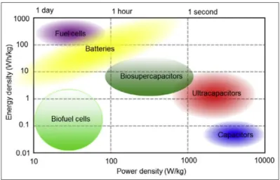
However, regarding power and energy density, the values achieved from
biodevices are very low when compared with conventional electric
power sources (Figure 2). By definition, electric power is the rate at
which electrical energy is transferred to an electric circuit (Fowle,
1978). This rate is low in the case of biological power sources due to
inadequate communication between the active site of the biocatalysts
and the electric circuit, specifically the conductive support that
configures the electrode (Figure 3) (Masa and Schuhmann, 2016; Shleev
et al., 2016), and other factors, e.g. high internal resistance of
biodevices.
The catalytic mechanisms of the biocatalysts used in this work, the
strategies employed to overcome the electron transfer (ET) limitation,
and the different types of biological power sources completed are
detailed below. The design of the bioelectrocatalytic devices included
selecting materials and surface modifications that targeted increased
power output and stability, as well as to favour possible wearable
device applications.
Biocatalysts
Electrocatalysis is a type of catalysis that results in the improvement of
the rate of an electrochemical reaction taking place on an electrode
surface. The term biocatalysis refers to the same process but concerning
the acceleration of electrochemical reactions carried out by biological
catalysts (Masa and Schuhmann, 2016; Tarasevich, 1985). The
biocatalysts used in this work include redox enzymes (oxidoreductases)
and organelles.
Oxidoreductases
Oxidoreductases are catalytic proteins that catalyse a coupled oxidation
and reduction. (Price and Stevens, 1982; Toone and Editor, 2007).
They transfer at least one electron between two or more substrates,
mediated by a cofactor (Milton and Minteer, 2017).
Figure 3. Schematic representation of the mechanism of a cathodic
bioelectrocatalytic system which contain several redox centers (A and B) (Shleev et
al., 2016).
The cofactors vary the oxidation state while catalysis is taking place,
and there are several possible cofactors for oxidoreductases (Rasmussen
et al., 2016). In this work, the oxidoreductases used incorporate the
following cofactors:
-
Flavin adenine dinucleotide (FAD) in glucose oxidase (GOx)
(paper I) and in the dehydrogenase (Dh) domain of cellobiose
dehydrogenase (CDh) (paper II and, III)
-
Pyrroloquinoline quinone (PQQ) and FAD in glucose
dehydrogenase (GDh) (paper III)
-
Heme in the cytochrome (CYT) domain of CDh (paper II and III)
-
Copper ions in bilirubin oxidase (BOx) (paper II, III and IV)
As regards enzymatic bioelectrocatalytic oxidation and reduction, the
electrode acts as one of the substrates, behaving as electron acceptor or
donor, respectively (Milton and Minteer, 2017). However, the enzyme
cannot establish direct communication with the electrode in every case,
owing to the fact that the active site of some enzymes appears to be
deeply buried within the protein, at a distance that does not allow
proper electric communication with the electrode (Bartlett et al., 1988;
Barton et al., 2001; Masa and Schuhmann, 2016). Therefore, the design
of the bioelectrochemical systems developed in this work has been
adapted to a particular biocatalyst, as explained below.
Anodic enzymes
Glucose oxidase
GOx, i.e. β-D-glucose:oxygen-1-oxidoreductase, is the anodic enzyme
used in paper I. In the paper, GOx from two different fungal species,
viz. Aspergillus niger and Penicillium amagasakiense, were used. Both
oxidoreductases are globular proteins with an average diameter of 8 nm
(Bourdillon et al., 1980; Wilson and Turner, 1992). The enzyme is a
dimer composed of two identical subunits, each containing two FAD
cofactors. The FAD is bound tightly in GOx and undergoes reduction
and oxidation without dissociating from the apoenzyme (Swoboda,
1969).
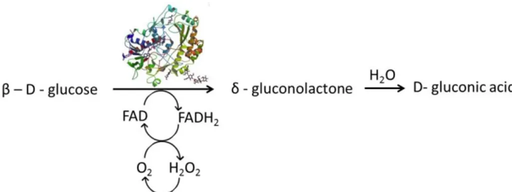
GOx catalyses the oxidation of β-D-glucose to glucono-δ-lactone,
which subsequently hydrolyses spontaneously to gluconic acid
(Leskovac et al., 2005). The two protons and electrons gained from
glucose oxidation fully reduce the FAD cofactor to FADH
2, that in turn
is re-oxidised by reducing oxygen to hydrogen peroxide (Figure 4)
(Wilson and Turner, 1992).
In addition to oxygen, the enzyme GOx can be oxidised by a large
number of other electron acceptors. In paper I, an organic salt,
tetrathiafulvalene-tetracyanoquinodimethane (TTF-TCNQ) is used as
diffusional electron acceptor that shuttles the electrons from the active
site of the enzyme to the surface of the developed electrodes, carrying
out mediated electron transfer (MET) (Chaubey and Malhotra, 2002;
Pauliukaite et al., 2007). In this organic salt, TTF is an electron donor
and TCNQ is an acceptor (Jaeger and Bard, 1980).
Figure 4. Catalytic mechanism of GOx. Glucose oxidation is coincidental with
FAD reduction (PDB file for GOx image: 1CF3).
In paper I, a specifically engineered GOx from Penicillium
amagasakiense (Courjean and Mano, 2011; Suraniti et al., 2013) is
used with the purpose of catalytic efficiency towards glucose, and
decreasing Michaelis constant, K
M,
in order to improve the
performance of the bioanode when subjected to low glucose
concentrations.
Cellobiose dehydrogenase
CDh, is an extracellular oxidoreductase secreted by wood degrading
fungi (Henriksson et al., 2000). Cellobiose is the natural substrate of
CDh. CDh is a monomeric enzyme composed of two domains: Dh and
CYT. The former is the catalytically active domain since it contains the
redox active cofactor FAD. The cofactor is non-covalently bound to Dh
and it is nested within the protein structure (Tan et al., 2015).
Figure 5. The catalytic mechanism of CDh from Neurospora crassa (NcCDh) in
which two electrons are obtained from the carbohydrate oxidation and transferred
to the FAD cofactor present in Dh domain and thereupon transferred to one or two
electron acceptors (1-EA and 2-EA) or to the CYT domain which transfers one
electron at a time either to an LMPO or to an electrode (Grippo et al., 2017).
The Dh domain is connected by a flexible linker to a CYT domain
(Zámocký et al., 2008). To re-oxidase FADH
2to FAD, CYT plays an
important role, acting as an electron mediator, with an iron containing
heme group. This metal ion interconverts between Fe
2+(reduced) and
Fe
3+(oxidised) states in order to transfer electrons (Henriksson et al.,
2001) from the Dh domain to an electron acceptor. The two domains
are separated by a distance of 9 Å, allowing efficient intramolecular
electron transfer (IET) (Tan et al., 2015).
CDh catalyses the oxidation of cellobiose to cellobionolactone, while
gaining two electrons. When present in wood degrading fungi, CDh
transfers the two electrons to electron acceptors, lytic polysaccharide
monooxygenases (LMPOs), as a consequence of the oxidation reaction
(Figure 5) (Flitsch et al., 2013).
In papers II and III, CDh from ascomycete Corynascus thermophilus
(CtCDh) was used as anodic enzyme to oxidise glucose, since CtCDh is
known to be a variant with high catalytic activity for this substrate at
neutral pH (Coman et al., 2010). CtCDh was able to communicate with
the electrode without mediators, in a direct electron transfer (DET)
reaction. The two protons and two electrons gained from glucose
oxidation fully reduce the FAD cofactor to FADH
2(Zámocký et al.,
2008).
Pyrroloquinoline quinone-glucose dehydrogenase
GDh, i.e. D-glucose: (pyrroloquinoline-quino) 1-oxidoreductase, is a
dimeric quinoprotein with two identical subunits that require the
presence of a quinone as cofactor to act as a catalyst (Oubrie et al.,
1999), and the quinone, PQQ, acts as a redox shuttle (Laurinavicius et
al., 2004). PQQ dependent GDh has been broadly used to replace GOx
(Tsujimura et al., 2006) because GDh does not rely on molecular
oxygen as the electron acceptor (Schubart et al., 2012).
The enzyme oxidises a broad range of carbohydrates to the
corresponding lactones, with concomitant reduction of PQQ to PQQH
2and it is able to donate electrons to various artificial electron acceptors
(Figure 6) (Matsushita et al., 1989; Oubrie et al., 1999). In paper III,
PQQ-GDh was used as anodic enzyme for glucose oxidation and DET
was achieved between the enzyme and the surface of the electrode,
corroborating previous reports (Murata et al., 2009; Razumiene et al.,
2006; Zayats et al., 2005).
Cathodic enzyme
Bilirubin oxidase
BOx, with the systematic name bilirubin:oxygen oxidoreductase, is a
monomeric redox enzyme that belongs to the group of multicopper
oxidases (MCOs) (Shleev et al., 2005). Specifically, BOx is a MCO that
carries four copper ions, i.e. T1, T2 and the binuclear T3 site (Milton
and Minteer, 2017; Shimizu et al., 1999; Shleev et al., 2005; Solomon et
al., 1996). T1 is the copper ion that accepts electrons from reduced
substrates or electrodes, consecutively transferring electrons via an IET
pathway to the T2/T3 cluster (Ramirez et al., 2008). The latter cluster is
finally responsible for the four-electron
reduction of oxygen to water
(Figure 7) (Cracknell et al., 2011; Shimizu et al., 1999).
Figure 6. Catalytic mechanisms of PQQ-GDh (PDB file for PQQ dependent GDh
image: 5MIN).
MCOs, and specifically BOx, have been widely used as cathodic
enzymes for oxygen bioelectroreduction in BFCs (Coman et al., 2010;
Coman et al., 2008; Falk et al., 2012a; Falk et al., 2012b; Wang et al.,
2012b). In this work, BOx from Myrothecium verrucaria (MvBOx) has
been used in papers II and III in EFCs, and in paper IV in a solar
biosupercapacitor.
Organelles
The term organelle refers to specialised subunits within eukaryotic cells
that carry out specific functions (Kerfeld et al., 2005). One of these
specialised subunits, thylakoids, are responsible for the light-dependent
reactions during photosynthesis (Govindjee et al., 2016). Thylakoids
consist of a thylakoid membrane (TM) and thylakoid lumen. In this
thesis, thylakoid membranes were immobilised on an electrode surface
to obtain DET (paper IV).
A thylakoid membrane carries photosynthetic pigments and integral
proteins including photosystems I and II, ATP synthase, a cytochrome
b6f complex, and mobile electron carriers, such as plastoquinone and
plastocyanin (Figure 8). According to a previously published
investigation (Rasmussen and Minteer, 2014), electrons from the first
five photosynthesis ET steps are donated to electrodes with immobilised
TM.
Even when the biological components are deemed as suitable materials
to catalyse reactions of interest, their usage might be hampered by
limited long-term stability (Bornscheuer, 2003) due to chemical,
thermal (Jesionowski et al., 2014) or mechanical changes. As detailed
below, the particular procedure employed to immobilise biocatalysts to
or within the supports is crucial to overcome stability and ET
limitations, and to ensure performance enhancements of the biodevices.
Immobilisation of biocatalysts
The process of immobilisation involves attachment of a biocatalyst on a
conductive surface to generate heterogeneous biocatalytic systems. The
main objective of immobilisation is to secure the most robust and stable
composite, to avoid perturbation when the overall conditions change.
Figure 8. Schematic representation of TM with the components involved in the
light-dependent reactions of photosynthesis. Dashed black arrows: electron flow;
dashed red arrows: proton flow (Rasmussen and Minteer, 2014).
There are different types of immobilisation procedures (Figure 9), of
which the following have been used in the current work:
-
Physical absorption in which a physical interaction is established
between the electrode surface and the biocatalyst. This
interaction includes intramolecular interaction forces, ionic
interactions and hydrogen bonding, and hence the immobilisation
will be less robust (Datta et al., 2013; Haider and Husain, 2008;
Sardar and Gupta, 2005).
-
Covalent immobilisation methods based on the reaction between
enzyme amino acid side chains, e.g. arginine, aspartic acid or
histidine, with functional groups present on the surface of the
electrodes that have been chemically modified. This type of
immobilisation is stronger and avoids leakage of the biocatalyst
(Sheldon, 2007).
-
Physical entrapment with biopolymers, specifically with gelatine
which is a protein-based hydrocolloid material (Datta et al.,
2013; Sheldon, 2007) that retains the biocatalysts.
-
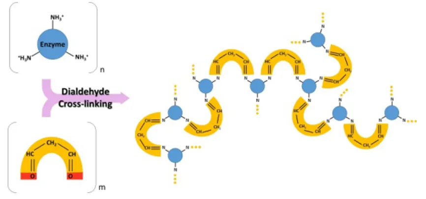
Crosslinking, specifically with glutaraldehyde, a molecule that
contains two aldehyde groups that can form covalent imine
bonds with amine groups from two different enzyme molecules
(Figure 10) (Szamocki et al., 2007). This process generates a
network of cross-linked enzymes.
Figure 9. Schematic representation of the different protein immobilisation
procedures.
In paper I. a GOx solution was dropped on the electrodes, enzyme
molecules were crosslinked and physically entrapped in a protective
layer of gelatine.
In papers II and III, CDh was covalently attached using aspartic and
glutamic acid residues present on the enzyme that were exposed to a
carbodiimide coupling agent and an auxiliary nucleophile (Figure 2, top
of
paper
II).
The
reactants
used
were
1-ethyl-3-(3-dimethylaminopropyl)carbodiimide (EDC) and N-Hydroxysuccinimide
(NHS) to generate an ester on the protein. The active ester present on
the protein can then react with amino groups on the chemically
modified [(3-aminopropyl)triethoxysilane (APTES)] electrode surface.
Both, EDC and NHS are water soluble and can be used in aqueous
media. There is the risk that the NHS esters formed on the protein
molecule may couple to other proteins. A different covalent
immobilisation protocol was used in the same papers for the cathodic
biocatalyst BOx and for the anodic enzyme PQQ-GDh (Figure 2,
bottom of paper II). In this case, the surface was chemically modified
with
(3-glycidyloxypropyl)trimethoxysilane
(GLYMO)
and
hydroxylated epoxy groups are expected to bind to amino groups
present on PQQ-GDh or BOx surfaces by generating secondary amino
groups (Abad et al., 2002).
Figure 10. Chemical reaction that leads to crosslinking of enzymes generating a
copolymer enzyme-glutaraldehyde.
Once the proper biocatalysts are selected and appropriate
immobilisation protocols are developed and optimised, the resulting
bioelectrocatalytic systems can be used to configure different biological
power sources, as explained further below.
Classification based on operational principle
Biological power sources can be classified in two groups, viz. BFCs and
biosupercapacitors (BSCs), Figure 11. BFCs can be conventional and
also charge-storing, when low and high capacitive bioelectrodes are
used, respectively. BSCs are devices based on highly capacitive
electrodes. Based on charging principles, these biodevices can be
classified as charging and conventional (without the ability to
self-charge) electric power sources.
Biofuel cells
As already mentioned, BFCs are power sources able to convert chemical
energy to electric energy using a biological material present on one
electrode, at least (Shleev et al., 2015), and usually at two electrodes.
On one of the electrodes the biomaterial catalyses the oxidation of a
certain biofuel and on the other electrode a different biocatalyst
catalyses the reduction of a biooxidant. In this way, flows of electrons
Figure 11. Classifications of electric power biodevices based on operational
principle.
Figure 12. Features that determine the performance of an EFC (Adapted with
permission from (Cracknell et al., 2008). Copyright 2008 American Chemical
Society).
and ions are established through the external circuit and the electrolyte,
respectively, as a consequence of the redox reactions taking place on
both electrodes.
The difference between the equilibrium redox potential of a
half-reaction and the potential at which the redox half-reaction is actually
observed, is called overpotential (Madan, 2015). In order to improve
voltage and power outputs of BFCs, one should select enzymes with the
lowest overpotentials for the oxidation and reduction reactions, thus
maximising the voltage, current, and power outputs of biodevices
(Figure 12).
It is known that BFCs deliver low power/current density but this is not
a serious limitation if the goal is to apply BFCs as power sources for
low energy demanding devices, such as biosensors or other low energy
consuming electronics (Barton et al., 2004; Gellett et al., 2010). Smart
approaches have already been developed, e.g. self-powered sensors that
use the analyte to be detected, as the fuel for the anodic electrode
(Grattieri and Minteer, 2018; Katz et al., 2001).
BFCs as power sources for wearable devices
Personalised medicine is being established as a way of improving the
quality of life of patients by self-monitoring, employing user-friendly
biomedical devices. Among the bioelectronics that are being designed
and developed, wearable devices seem to be a convenient alternative,
since they can be worn by the user with minimal invasion and no
requirement of expertise skills (Bandodkar, 2017; Falk et al., 2012a;
Katz et al., 2015; Willner and Katz, 2006).
The proposed wearable devices rely on microelectronics that need to be
suitably powered. A promising option is to implement energy sources
able to harvest electrical energy from chemical energy available in
physiological settings. In this thesis, the focus is on potential
applications of transparent, flexible, and nanostructured biological
power sources for wearable devices, such as smart electronic contact
lenses. On a self-contained ocular device, a tear-based biological power
source would generate stable power in pulse mode during several hours
as shown in paper III. However, apart from space limitations, other
issues, including consumption of biofuels and the biooxidants, must be
accounted for. The low concentration and low restoration rates of
biofuels present in tears leads to low power output by the EFC, when
performing in continuous mode.
In an ideal prototype of a smart electronic contact lens, an embedded
sensor would detect a particular analyte relevant for the subject and
forward the information wirelessly to a receiver. The sensor can detect
the analyte, and act as one of the electrodes of the EFC at the same
time. In this way the device is generating energy while
detecting/consuming the analyte. Several biofuels are available in
human lachrymal fluid, e.g. glucose, dopamine, ascorbic acid, while
molecular oxygen is the biooxidant (Falk et al., 2012a).
Different strategies have been adopted to overcome problems regarding
the power output needed to sustain the performance of the biodevice.
The direction that our research group promotes is the development of
thin, flexible and transparent biological power sources able to work in
pulse mode, taking advantage of the capacitive features of the electrodes
(Pankratov et al., 2014a; Pankratov et al., 2014b). Biological power
sources, assembled with highly capacitive electrodes constitute BSCs, a
term that is explained in more detail below.
Biosupercapacitors
A conventional capacitor is an element of an electrical circuit composed
by two metal sheets or plates, separated by a dielectric material, that
can be polarised by applying an electric field (Winter and Brodd, 2004).
Therefore, in a conventional capacitor a potential has to be applied
externally to accumulate opposite charges on each plate, see Equation
1:
𝐶 =
𝑄
𝐸
While the charging process is taking place, an excess of electrons
appears at one plate and a deficiency of electrons (excess of electron
holes) on the other one. In this type of capacitor, charges are
accumulated uniquely in the electric field between the plates (Winter
and Brodd, 2004).
Supercapacitors, also named electrochemical capacitors, do not have a
dielectric material but an electrolyte ionically connecting the plates.
Once the external voltage is applied, a charging process is initiated and
the electrodes are polarised, accumulating positive charges on the
positive electrode and negative charges on the negative electrode (Wang
et al., 2012a; Winter and Brodd, 2004).
A unique feature of the biosupercapacitors in the present work is that
there is no need to apply an external voltage to charge these devices
since the immobilised enzymes polarise both plates by catalysing redox
reactions that leads to an accumulation of charges of opposite sign on
the electrodes. The capacitive features, viz. ability to store electric
charges, of biosupercapacitors rely on different types of capacitance
based on reversible charge-transfer reactions (pseudocapacitance)
and/or electric double layer capacitance (Pankratov et al., 2014a;
Pankratov et al., 2014b) as in the “non-bio” electrochemical capacitors.
The capacitance of the electrodes for biological power sources is tightly
related to the materials used to construct them.
In order to understand the different types of capacitance and the criteria
to select the appropriate capacitive material for electrodes, some
important theoretical concepts are clarified below.
Electrical double layer
When any type of electrode is immersed in an electrolyte solution, a
specific interfacial region, the double layer, is formed. The electrical
properties of this layer influence the electrochemical measurements. In
the electrochemical setup used to measure the current that flows at a
working electrode (WE), the electrical double layer (EDL) can be
considered as a capacitor. This EDL capacitor must be charged in order
to obtain a desired potential at the WE. This involves the flow of a
capacitive current in the electrical circuit, not related to any redox
process. The capacitive current can be used for analytical purposes since
it incorporates information about the double layer (Bak et al., 2011;
Kyotani et al., 1996; Wang et al., 2012a).
There are several models published in the literature to describe the
structure of the double layer, but there is no general model that applies
to all cases. The combination of several factors, such as type of material
of the WE, type of solvent or supporting electrolyte, determine the
structure of the double layer.
Helmholtz was first in introducing to the scientific community the
concept of a double layer at the surface of a metal in contact with an
electrolyte. His model included a compact layer of ions in contact with
the charged metal surface. Gouy and Chapman proposed later a model
that includes a diffuse double layer in which the ions move to certain
distance from the surface of the electrode. The physicist Stern described
the double layer with a model that combined the two previous ones, the
rigid Helmholtz layer and the diffuse layer of Gouy and Chapman.
Many more models followed later, to complete the description of the
double layer (Pletcher and Editor, 2009).
A simplified model is shown in Figure 13 including two planes as
proposed by Helmholtz:
• Inner Helmholtz plane (IHP): electrode surface reached only by
solvent molecules. It is formed by specifically adsorbed ions.
• Outer Helmholtz plane (OHP): formed by charged species that
can approach the electrode just to certain distance since they
are anions and cations surrounded by solvent molecules.
Figure 13. Scheme representing the different layers within the electric double
layer (M= metal).
Faradaic and non-faradaic processes
The reactions governed by Faraday’s law (Equation 2) are called
faradaic processes. In these reactions the charges are transferred across
the electrode-solution interface due to the ET that constitutes oxidation
or reduction reactions.
𝐼 ×𝑡 = 𝑛×𝑧×𝐹
Where I is current; t is time; n is the number of moles of the product; z
is the valency of ions of the product; F is Faraday’s constant equivalent
to 96500 C mol
-1.
Non faradaic processes do not involve charge-transfer reactions.
However, they take place when a changing potential or solution
composition modifies the structure of the electrode-solution interface,
due to adsorption or desorption processes that translates to external
current flow even though charge does not cross the interface (Bard and
Faulkner, 2001).
Hence, the following classification for capacitors based on type of
capacitance can be established (Frackowiak and Beguin, 2001; Wang et
al., 2012a; Zhang and Zhao, 2009):
-
Electric double layer capacitors (EDLCs): store energy by
accumulating ions present in the electrolyte, physically
absorbed/desorbed to form a double layer on electrodes with
specific surface area. In this case charges are stored
electrostatically.
-
Pseudocapacitors:
in
this
case
charges
are
stored
electrochemically by faradaic redox reactions with
charge-transfer between the electrolyte and the electrode.
-
Hybrid capacitors: combine an electrode that store charges
electrochemically
with
an
electrode
that
store
them
electrostatically (Pankratov et al., 2014a).
Capacitive nanostructured materials
The selection of the proper conductive and capacitive materials is
relevant in order to maximise the capacitance of the devices.
The capacitance of the electrodes for BSCs strongly depends on the
surface area of the electrode, accessible to the electrolyte. There are
three general groups of materials used in this work for BSCs:
• Carbon based materials with high specific surface area. These
materials have the advantage of being abundant, inexpensive,
and easy to produce. In addition they are non-toxic with
excellent electric conductivity, combined with high chemical
stability and wide operating temperature range (Kyotani et al.,
1996; Ruiz et al., 2007). They store charges mostly in an ECDL
at the electrode/electrolyte interface, and hence, the capacitance
depends largely on the surface area accessible to the electrolyte
ions (Wang et al., 2012a). Multiwall carbon nanotubes
(MWCNTs) and graphene flakes are high surface area
carbon-based materials used in paper I.
• Conducting polymers are faradaic materials. They are
inexpensive, have high conductivity in an appropriately doped
state, high voltage window and high storage capacity (Kalaji et
al., 1999). Conducting polymers show capacitive behaviour
through redox processes; when oxidation takes place, ions are
transferred to the polymer backbone and when reduction
occurs, ions are released to the electrolyte. These redox
reactions take place in the entire polymer bulk, not just on the
surface (Wang et al., 2012a). In paper I, the conductive polymer
poly(3,4-ethylenedioxythiophene) (PEDOT) was used. When
PEDOT is electrochemically deposited on an electrode, a highly
porous amorphous film is obtained, which allows higher
capacitance values than for electrodes based on activated
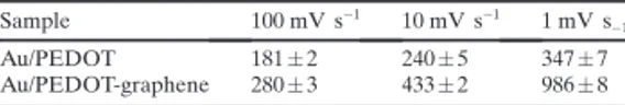
carbons (Li et al., 2005). In paper I, a combination of
capacitance through redox processes and through ECDL was
accomplished by forming a PEDOT-graphene composite.
• Metal oxides can provide higher energy density for
electrochemical supercapacitors than conventional carbon
materials, and metal oxides are more stable than conducting
polymers (Wang et al., 2012a). They store energy
electrostatically, but also support electrochemical faradaic
reactions between electrode and ions within an appropriate
potential window (Bak et al., 2011). The metal oxide chosen
has to be electrically conductive and two or more oxidation
states must be accessible. When electrodes where constructed
using metal oxide nanoparticles (NPs), as in paper II, III and IV
with ITONPs, the ability of storing charges in both faradaic and
non-faradaic modes was promoted.
In addition to capacitance, important features of supercapacitors in our
studies
were
operational
stability
(when
applying
several
charge/discharge
cycles)
and
transparency.
In
the
case
of
biosupercapacitors, as already mentioned, there is no need of applying
an external voltage since the biocatalysts polarise the electrodes. In
paper I with a capacitive bioanode and in paper III with an
EFC/biosupercapacitor, self-charging of the cells was monitored with
potentiometry at zero current. Discharge was triggered by applying a
potential pulse using amperometry (paper I) or by connecting the circuit
to an external resistor (paper III and IV). The electroanalytical methods
are explained in the next section.
EXPERIMENTAL METHODS
Microscopy
Atomic force microscopy
Atomic force microscopy (AFM) is a tool that allows the visualisation
at the nanoscale. It works by raster scanning a surface with a sharp tip
(the radius of its apex is typically in the range of a few nanometers)
attached at the free end of a soft micro-cantilever. In most AFM setups,
the sample is placed on top of a piezoelectric tube (the scanner), so that
its position can be controlled with sub-nanometer precision. A similar
precision is achieved in the monitoring of the deflection of the
cantilever, commonly with an optical detection system.
This consists in focusing a laser beam on the free end of the cantilever,
and monitoring the reflected beam with a segmented photodetector
(Figure 14). Both the positioning system and the photodetector signals
are connected to an electronic unit that is computer-controlled. AFM
can be operated in a variety of modes.
In this thesis, tapping mode has been used. In tapping mode, the
amplitude of the oscillation of the micro-cantilever, and thus the
average distance between tip and sample, is kept constant while
scanning the sample by adjusting its vertical position during the process.
The topography of the sample is then reconstructed by inverting its
vertical movements during the scan.
AFM has been used in this thesis as a useful tool to characterise
nanostructured surfaces. In paper II (supporting information), 2D and
3D representations of the nanostructured surface of electrodes were
obtained, with the corresponding height profiles. This characterisation
allowed the determination of the thickness and degree of uniformity of
the layer of ITONP used to nanostructure the electrodes.
Scanning electron microscopy
Scanning electron microscopy (SEM) uses an electron beam to scan the
surface of the sample. The atoms of the sample become excited by the
electron beam, emitting secondary electrons. An electron detector
collects the secondary electrons that allows rendering of an image
(Figure 15).
In papers I and II SEM images allowed us to characterise the conductive
nanostructured surfaces used in our studies. Samples were characterised
in high vacuum mode.
Spectral methods
While there are several spectral methods, widely used in research
nowadays, ultraviolet-visible (UV-Vis) spectrophotometry was exploited
in this thesis.
Ultraviolet-visible spectrophotometry
Spectrophotometry is the quantitative measurement of absorption and
transmission properties of materials as function of wavelength. The
absorption of UV-Vis radiation by a material involves the excitation of
electrons in atoms and molecules. The light will be absorbed just if it
has the amount of energy needed to excite the electrons from a lower to
a higher energy level. The wavelength of light that has the energy
required to cause one of the electronic transitions will be absorbed.
UV-Vis spectrophotometry was used in this thesis to measure the
absorbance of light by a sample, performing scans within a certain
range of the spectrum. The UV light region appears in the wavelength
range ca. 190-400 nm and the visible light in the range ca. 400-800 nm.
Absorption and transmission spectra have been obtained and
interpreted in some of the papers in this thesis. Specifically, in paper I
and II, UV-Vis spectrophotometry has been used to evaluate the
transmittance and absorbance of the different conductive surfaces used
to shape transparent electrodes.
Electrochemical methods
Electrochemical methods have been employed to study different systems
in this work. In order to apply these methods and interpret the obtained
results it is important to understand fundamental principles of electrode
reactions and the electrical properties of electrode-solution interfaces.
Parameters, such as electrochemical potential, standard potential and
formal potential are important terms in electrochemistry, as explained
below.
Electrochemical potential
For a better understanding of electrochemical potential, firstly the
definition of chemical potential has to be considered. From a
thermodynamic point of view, the chemical potential is the rate of
change of the free energy needed to be cumulated or released by a
species during a chemical reaction or a phase transition (Huebner and
Barfield, 2014). Generally, there is a tendency to move from a higher
energy level to a lower energy level, releasing free energy. However, in
the term “chemical potential” the electric forces that are present in the
surroundings of an ion, influencing its motion, are not considered.
Consequently, the electrochemical potential includes the energy
contribution of electrostatics in addition to the energy quantity
determined by the chemical potential. In electrochemistry, ions move
from a region with higher electrochemical potential to a region with
lower electrochemical potential.
Standard potential
Specifically and by convention, the standard potential (E°) is the
measure of the electrode potential for a half-reaction of a redox process
under standard conditions, i.e. 25
°C, at 1 atm pressure and with
solutes at an effective concentration of 1 mol dm
-3(Bard and Faulkner,
2001). The potential in electrochemical experiments can be driven at
the electrode (by an external power supply) to negative potentials
causing the electrons to reach levels of energy high enough to be
transferred to empty electronic states on species present in the
electrolyte. This flow of electrons from the electrode to the electrolyte is
a reduction current. Alternatively, the potential can be driven to
positive potentials so the electrons on species present in the electrolyte
will transfer to the electrode for a more favourable energy level, that
translates into a flow of electrodes from the electrolyte to the electrode,
which is an oxidation current (Bard and Faulkner, 2001). The
potentials, at which these oxidation and reduction processes take place,
are tightly related to the standard potential of a chemical species. The
standard potential of a cell or half-reaction is obtained under
conditions, where all species are in their standard states (Bard and
Faulkner, 2001).
Formal potential
The formal potential (E°’) relates to specific conditions, which divert
from the standard conditions already mentioned.
Formal potential is a very convenient parameter to evaluate half-cell
potentials since very often the activity coefficients of the chemical
species involved are unknown. The formal potential incorporates the
For instance, if we consider the half-reaction:
𝑜𝑥𝑖𝑑𝑎𝑛𝑡 + 𝑒
!→ 𝑟𝑒𝑑𝑢𝑐𝑡𝑎𝑛𝑡
If the kinetics of ET are fast, the concentration of the oxidant ([Ox])
and the concentration of the reductant ([Red]) at the electrode surface
can be assumed to be at equilibrium with the electrode potential, as
governed by the Nernst equation for the half-reaction, which includes
concentrations instead of activities and formal potential instead of
standard potential:
𝐸 = 𝐸
!+
𝑅𝑇
𝑛𝐹
ln
𝑎
!"𝑎
!"#= 𝐸
!+
𝑅𝑇
𝑛𝐹
𝑙𝑛
𝛾
!"𝑜𝑥
𝛾
!"#𝑟𝑒𝑑
Which is
𝐸 = 𝐸
!"+
𝑅𝑇
𝑛𝐹
𝑙𝑛
𝑜𝑥
𝑟𝑒𝑑
Where
𝐸
!"= 𝐸
!+
𝑅𝑇
𝑛𝐹
ln
𝛾
!"𝛾
!"#The way of determining values of standard potentials for half-reactions
and cells is by measuring formal potentials values at different ionic
strengths and extrapolating them to zero ionic strength, where the
activity coefficients are close to unity (Bard and Faulkner, 2001).
Open circuit potential and voltage
Open circuit potential (OCP) and open circuit voltage (OCV) are the
difference of potential between two terminals, when no external electric
current flows between the terminals. It implies that a pair of redox
forms linked by a given half-reaction (redox couple) is present at each
electrode, establishing a true equilibrium.
(3)
(4)
(5)
For instance, two half-reactions in the case of glucose/oxygen BFCs are
the following:
𝑔𝑙𝑢𝑐𝑜𝑛𝑜𝑙𝑎𝑐𝑡𝑜𝑛𝑒 + 2𝐻
!+ 2𝑒
!→ 𝑔𝑙𝑢𝑐𝑜𝑠𝑒
𝑂
!+ 4𝐻
!+ 4𝑒
!→ 𝐻
!