DOCT OR AL DISSERT A TION IN ODONT OL OG Y MIC HAEL BR AIAN MALMÖ UNIVERSIT
DIGIT
AL
DENTIS
TR
Y
MICHAEL BRAIAN
DIGITAL DENTISTRY
Studies on the trueness and precision of additive
manufacturing and intraoral scanning
Malmö University, Faculty of Odontology
Doctoral Dissertation 2018
© Copyright Michael Braian 2018
Photographs and illustrations: Michael Braian ISBN 978-91-7104-940-7 (print)
MICHAEL BRAIAN
DIGITAL DENTISTRY
Studies on the trueness and precision of additive
manufacturing and intraoral scanning
Malmö University, 2018
Department of fixed prosthodontics
Faculty of Odontology
The publication is also available in electronic format at muep.mau.se
“Set your goal and conquer it” Mohsen and Parvin Braian
TABLE OF CONTENTS
LIST OF PUBLICATIONS ... 11
THESIS AT A GLANCE ... 12
ABSTRACT ... 14
POPULÄRVETENSKAPLIG SAMMANFATTNING ... 17
ABBREVIATIONS AND DEFINITIONS ... 19
INTRODUCTION ... 21
Metrology ...21
Accuracy and Precision ...21
Repeatability and Reproducibility ...22
Validation ...23
Measurements ...23
Tolerance, allowance and clearance ...24
CONVENTIONAL WORKFLOW FOR FIXED PROSTHODONTICS ... 26 Conventional impression ...26 Stone model ...28 Die processing ...28 Wax up ...29 Investment ...29 Casting ...30 Post-processing ...30
PARTIALLY DIGITAL WORKFLOW FIXED PROSTHODONTICS .. 31
Extraoral scanner ...31
COMPLETELY DIGITAL WORKFLOW
FOR FIXED PROSTHODONTICS ... 33
Intraoral scanner ...33 History ...33 Light source ...33 Working principles ...34 Triangulation ...34 Confocal microscopy ...35 Data processing ...35 Point cloud ...35 Post-processing ...36 Scanning strategy ...38
Accuracy of intraoral scanners ...40
Computer-aided design ...41
Design perimeters ...42
Computer-aided manufacturing ...43
Subtractive manufacturing ...44
Accuracy of subtractive manufacturing...46
Additive manufacturing ...46
History ...46
Product development ...47
The STL file ...48
Fabrication principles ...48
Additive manufacturing applications in dentistry ...49
Accuracy of additive manufacturing of polymer constructions . 50 Build orientation ...51
Accuracy of additive manufacturing of metallic constructions .. 52
DIGITAL VERSUS CONVENTIONAL WORKFLOW ... 53
Production tolerances in dentistry ...54
Marginal fit ...54
Final remarks ...55
HYPOTHESIS ... 56
SPECIFIC AIM ... 57
MATERIALS AND METHODS ... 58
Study I ...58
Study II ...62
RESULTS ... 73 Study I ...73 Study II ...75 Study III ...80 Study IV ...89 DISCUSSION ... 95 Discussion on methods ...95 Study I ...95
Studies II and III ...101
Study IV ...110
Discussions on results ...117
Study I ...117
Studies II and III ...118
Linear measurements ...118
Degree and corner radius measurements ...122
Inter-observatory variability ...125 Study IV ...126 CONCLUSIONS ...130 ACKNOWLEDGEMENTS ...131 REFERENCES ...132 PAPERS I–IV ... 143
LIST OF PUBLICATIONS
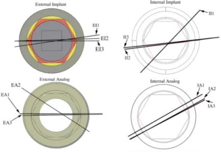
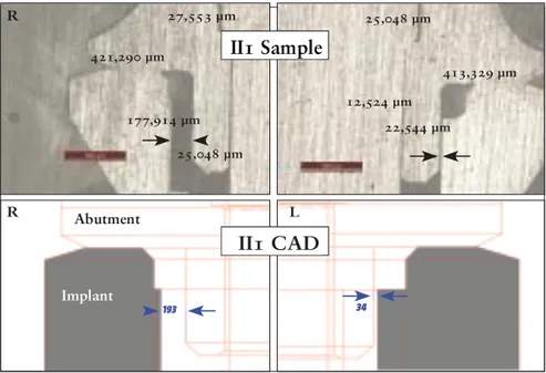
I. Tolerance measurements on internal- and external-hexagon implants. Braian M, De Bruyn H, Fransson H, Christersson C, Wennerberg A. Int J Oral Maxillofac Implants. 2014 Jul-Aug;29(4):846-52.
II. Production tolerance of additive manufactured polymeric objects for clinical applications. Braian M, Jimbo R, Wennerberg A. Dent Mater. 2016 Jul;32(7):853-61 III. Geometrical accuracy of metallic objects produced with
additive or subtractive manufacturing: A comparative in vitro study. Braian M, Jönsson D, Kevci M, Wennerberg A. Dent Mater. 2018 Jul;34(7):978-993
IV. Trueness and precision of five intraoral scanners on scanning edentulous and dentated full arch mandibular casts: A comparative in vitro study. Braian M. DDS, CDT, Wennerberg A, DDS, Ph.D. Accepted, journal of prosthetic dentistry
THESIS AT A GLANCE
To present the horizontal clearance of the
interface between internal-hexagon and
external-hexagon implants and analogues with
corresponding cylindric gold and plastic
abutments upon delivery from the implant
manufacturer.
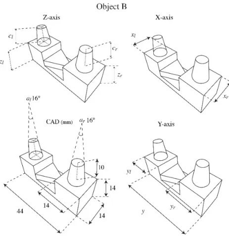
To determine the production accuracy of four
commercially available polymeric additive
manufacturing systems by reverse engineering
two geometrical objects.
To evaluate the production accuracy of five
additive manufacturing systems and one
subtractive manufacturing system for the
production of metallic components by reverse
engineering two geometrical objects
To study the accuracy of four different intraoral
scanners for full-arch scanning of one
edentulous model and one dentated model.
I
II
III
IV
Prefabricated gold abutment on
internal-hexagon implants showed tolerances <90 µm.
In contrast, prefabricated plastic cylinders
showed errors of <100 µm for external-hexagon
implants and <130 µm for internal-hexagon
implants.
To present the horizontal clearance of the
interface between internal-hexagon and
external-hexagon implants and analogues with
corresponding cylindric gold and plastic
abutments upon delivery from the implant
manufacturer.
To determine the production accuracy of four
commercially available polymeric additive
manufacturing systems by reverse engineering
two geometrical objects.
To evaluate the production accuracy of five
additive manufacturing systems and one
subtractive manufacturing system for the
production of metallic components by reverse
engineering two geometrical objects
To study the accuracy of four different intraoral
scanners for full-arch scanning of one
edentulous model and one dentated model.
I
II
III
IV
Prefabricated gold abutment on
internal-hexagon implants showed tolerances <90 µm.
In contrast, prefabricated plastic cylinders
showed errors of <100 µm for external-hexagon
implants and <130 µm for internal-hexagon
implants.
ABSTRACT
Artificial designs and features usually control production workflows in the industry. The operator has the freedom to adapt designs to achieve the desired function; when the operator is satisfied, mass production of the two objects is possible. The production workflow for prosthetic restorations in dentistry is a fairly complicated procedure that requires several well-controlled processes, and each unit is individually adapted to one unique situation. The aim of the final restoration is to replace damaged or missing soft and hard tissue, and to restore function, phonetics and aesthetics. The restoration has high material property requirements in order to withstand high forces, thermal changes, aging and humidity. If the fit of the reconstruction is insufficient there is a high probability for clinical failures ranging from inflammatory processes to reconstruction fractures. The grading of perfect, sufficient and insufficient fit is unknown although the definition clinically acceptable fit has been used to describe and control a reconstruction that is well seated and controllable by the clinician. Study I in this thesis focuses on the clearance (play) between different implant components in order to achieve a threshold value for how accurate the production in dentistry needs to be. We found that metallic components on external hex connections have a clearance
of approximately 50 µm.
Not only is every case individually designed and manufactured, but the receiving intraoral part also needs to be replicated into an extraoral part ahead of production, a procedure that has been possible with different impression materials. Subsequently, the production
goes through a series of controlled compensations to fit the intraoral situation. The conventional workflow starts by the selection of an impression tray, ranging from custom-made trays to plastic stock trays. The ideal trays are rigid, thereby minimising flexure during the impression taking. There are several types of impression materials with different properties regarding setting time, volume changes and mechanical properties. The next step in the conventional workflow is the casting of the impression. There are various types of gypsum products utilised in dentistry, and they require different amounts of water. The differences depend on the shape and compactness of the crystals. Type IV dental stone gypsum is often used in reconstructive dentistry with a typical setting expansion of 0.10%. For the partial digital workflow the same volume changes can be seen for the conventional impression, the stone model production and the die processing. In order to design the intended construction digitally instead of using wax, the model needs to be digitised in an extraoral scanner, also known as desktop scanner.
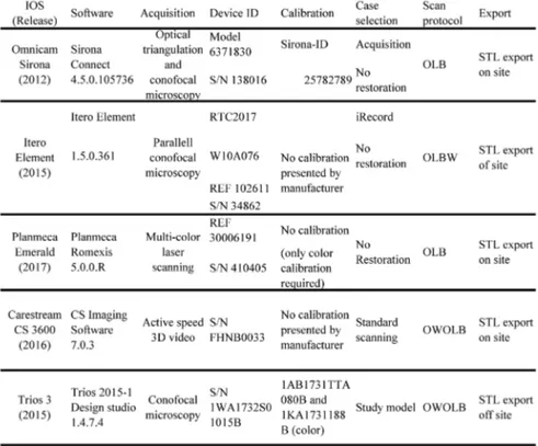
The fully digital workflow consists of a direct digitisation of the oral cavity utilising intraoral scanning devices. All intraoral scanners have the same goal, to digitise the size, shape and surface of a physical object into a geometrical virtual shape. This acquisition needs to be repeatable, reproducible and accurate. The IOS manufacturers try to achieve these goals with different hardware and software setups. Study IV focuses on the acquisition accuracy of five different intraoral scanners for the digitisation of edentulous and dentated models. The results suggest that the devices had lower accuracy for the digitisation of the edentulous models when compared to the dentated model. Furthermore, Study IV presented observations suggesting that full-arch scans had lower accuracy when compared to shorter full-arch scans on both models. For the cross-arch measurements on the edentulous scans, the trueness values ranged from 6 µm to 193 µm, and, for the shorter arch measurements, the results ranged from 2 µm to 103 µm. For the dentated cast, the cross-arch trueness values ranged from 6 µm to 150 µm, and, for the shorter arch measurements, the results ranged from 4 µm to -56 µm.
The digitised file is then utilised as a virtual model by a computer-aided designer in order to virtually design the intended reconstruction. The designed file is then manufactured utilising computer-aided manufacturing, which can be performed either by a subtractive machine (milling) or by additive systems (3D printing). Study II and Study III explore the production tolerances for producing polymeric and metallic objects from additive systems. Study III also contained a subtractive group. The results from these two studies suggest that all tested additive systems for producing polymeric objects were, on average, <20 µm for both precision and trueness, and the additive systems for manufacturing metallic objects ranged from >500 µm to <30 µm in trueness, with precision values of <100 µm. The subtractive system showed trueness values of <25 µm with a precision around 20 µm.
POPULÄRVETENSKAPLIG
SAMMANFATTNING
Vid mindre tandskador och hål i tänderna, kan tandläkaren laga dessa direkt inne i munnen med plastfyllningar. Men om skadan är större, eller om tanden är så pass skadad att den måste dras ut, måste tandvården använda sig av andra material för att återskapa den förlorade tanden. Vid större skador får man oftast tillverka en krona eller en bro, en krona ersätter skador på en tand och en bro ersätter en eller flera förlorade tänder. Kronor och broar kan inte tillverkas direkt i munnen, dessa måste framställas av en tandtekniker i ett tandtekniskt laboratorium. För att kunna göra detta måste tandteknikern ha en gipsmodell av patientens tänder. I decennier har tandläkarna tagit avtryck med en metallsked i patientens mun och sedan skickat det avtrycket till tandteknikern som i sin tur hällt i gips för att framställa modellen. Därefter använder tandteknikern vax för att bygga upp det som saknas och med hjälp av gjutning kan man sedan få fram ett metallskelett. På metallskelettet lägger man porslin för att efterlikna vanliga tänder. Idag finns det modernare tekniker för tandvården att använda, både för tillverkningen och för avtrycket. En studie i avhandlingen har undersökt hur pass bra en 3D scanner kan avbilda patientens tänder. I stort sett filmar då tandläkaren tänderna från alla möjliga vinklar, sedan sätts filmen ihop till en tredimensionell digital modell, som skickas över internet till tandteknikern. Tandteknikerna kan sedan forma kronan eller bron direkt i datorn, när formen är klar kan denna framställas i en datorstyrd fräsmaskin eller av en 3D printer. Två av avhandlingens
studier har tittat på hur pass bra olika 3D printrar är på att framställa relevanta former. Ingen av studierna har gjorts inne i munnen på patienter, så man bör vara lite försiktig med att dra för stora slutsatser. Avhandlingen visar dock på att både 3D scanningen och 3D printrarna har stor potential att kunna ersätta eller komplettera det traditionella sättet att framställa kronor och broar.
ABBREVIATIONS AND DEFINITIONS
Accuracy Closeness of agreement between a measured
quantity value and a true quantity value of a measurement
Allowance Amount of designed intentional deviation
AM Additive manufacturing
CAD Computer-aided design or computer-assisted design
CAM Computer-aided manufacturing or computer-assisted
manufacturing
Clearance The distance between two mating dimensions
DLP Digital light processing
DMLS Direct metal laser sintering
IOS Intraoral scanner
Precision Closeness of agreement between measured quantity
values obtained by replicate measurements on the same or similar objects under specified conditions
Repeatability Condition of measurement, out of a set of conditions
that includes the same measurement procedure, operators, measuring system, operating conditions and location, and replicates measurements on the same or similar objects over a short period of time Reproducibility Condition of measurement, out of a set of conditions
that includes different locations, operators, measuring systems, and replicate measurements on the same or similar objects
SLA Stereolithography
SLS Selective laser sintering
SM Subtractive manufacturing
STL Standard tessellation language or stereolithography
STEP Standard for the exchange of product model data
Tolerance Total amount that a specific dimension is permitted
to vary
Traceability Property of a measurement result whereby the result
can be related to a reference through a documented unbroken chain of calibrations, each contributing to the measurement uncertainty
Trueness Closeness of agreement between the average of an
infinite number of replicate measured quantity values and a reference quantity value
INTRODUCTION
Metrology
Metrology is the science of measurement and its applications. The measure is used to communicate size, quantity, position, condition and time.
Accuracy and Precision
Two terms are central to understanding metrology: accuracy and precision. Accuracy relates to the closeness of a measured value to a standard or a known (true) value, whereas precision pertains to the closeness of measured values to each other. Figure 1 illustrates the correlation between these two terms, if the centre of the target would be referred to as the true value or the standard, then Figure 1a shows a result that has both low accuracy and precision. In contrast, Figure 1d illustrates results that are both accurate and precise. When conducting research, it is normal to calculate the standard deviation (SD) and the mean value of a measurement (mean). Relating these two terms to the metrological nomenclature would correlate the mean value as accuracy and the standard deviation to precision. ISO 5725-1[1] uses two terms to describe accuracy; the first is precision and the second is trueness. Trueness is described as closeness of agreement between the calculated mean from several measurements in comparison with a true or accepted reference value. If ISO 5725-1 is used as reference, then all accuracy legends in Figure 1 would change to trueness and image d) would be regarded as accurate and a) as not accurate, meanwhile image b) would be described as having a low trueness; the shooter is precise but not accurate. Only Study IV in this thesis has used the ISO 5725-1 definition.
Figure 1. Illustration of the correlation between accuracy and precision.
Repeatability and Reproducibility
The typical term for irregularity between repeated measurements is precision. For describing the irregularity of a measurement method two conditions of precision have been found necessary, termed repeatability and reproducibility. Under repeatability conditions, the following factors:
1. Operator 2. Equipment used 3. Equipment calibration
4. Environment (temperature, humidity, air pollution, and so forth)
5. Time elapsed between measurements
are considered constants and do not contribute to the variability, while, under reproducibility conditions, they vary and do contribute to the irregularity of the test results. Hence, repeatability and reproducibility are the two extremes of precision, with the first describing the lowest and the second the highest variability in results [1].
Validation
Figure 1a would illustrate measuring equipment that has low accuracy and precision for measuring that specific object. It could also mean that the objects being measured are both manufactured inaccurately and imprecisely. To remove one of these errors, the measurement equipment should be validated if the true value (bull’s eye) is exactly
10 mm ± 0.10 mm, the measuring device should be validated to be
greater. The validation is also referred to as quality assurance or quality control. The process of quality assurance would require the operator to measure an object with known dimensions to validate the measuring equipment. One example of objects with known dimensions is gauge blocks; the reason why their dimensions are referred to as known is that they have been measured by measuring
equipment with extreme accuracy, generally on an ≤1 µm level.
Measurements
The core challenge of metrology is that the measuring tool used to measure an object must have a reference of greater accuracy, this is referred to as traceability. Without traceability, measurements are meaningless at best and could even be misleading. This means that the tool being used to measure an object requires the capability to measure that specific object with higher accuracy than the process in which it is going to be used. All measurements consist of the part, the measuring device and the standard or the known value, see Figure 2. No measurements can be made with perfect accuracy. An instrument, when repeatedly subjected to the same input, may not indicate the same output. Response of an instrument may change with time due to wear. Environmental conditions such as temperature, pressure and humidity could affect the outcome. To achieve a reliable measurement, the operator needs to decrease possible errors by measuring room temperature, heat transformations, equipment conditions, and so forth.
Figure 2. All measurements require these three elements.
Tolerance, allowance and clearance
Tolerance could also be described as “good enough”, i.e. all manufactured parts can vary in size or shape but still be satisfactory for their purpose. Tolerance is the total amount that a certain dimension is allowed to vary. Many objects such as drills, gears, threads and screws have specific tolerance requirements that are described by different standardisation organisations (United States Y14.5M and International Standards Organisation). Tolerance in manufacturing is strongly correlated to function, and the intended object should have good enough tolerances in order to function properly. On the contrary, allowance is when an operator intentionally over- or under-sizes a design in order to compensate for forthcoming machining procedures. One example would be the intended under-sizing of an object that will expand during a heat-treatment process. Clearance could be described as the air or space between two manufactured parts, as shown in Figure 3.
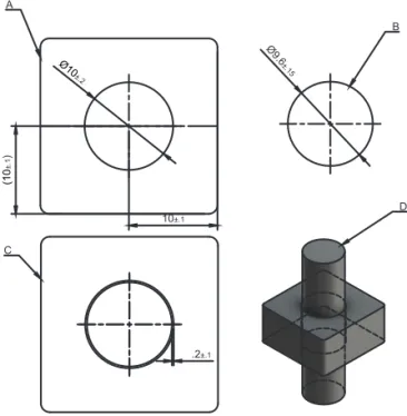
Ø10 ±.2 Ø9.6 ±.15 (10 ±.1 ) 10±.1 .2±.1 A B C D
Figure 3. Example of the tolerance between a cylinder and a hole. The cylinder (D and B) is designed to move freely in the axial direction. In order to achieve this, there are production tolerance requirements for the manufacturing of the cylinder and the counterpart (A and C). In this example, clearance would be the air between the cylinder and the hole, while tolerance would be all the ± markings.
CONVENTIONAL WORKFLOW FOR
FIXED PROSTHODONTICS
Artificial designs and features usually control production workflows in the industry; Figure 3 shows a two-part object in which both the product features are designed and controlled digitally. The operator has the freedom to adapt both designs to achieve the desired function; when the operator is satisfied, mass production of the two objects is possible. In the field of dentistry, the construction manufacturing is adapted to a specific case individually. Not only is every case individually designed and manufactured, but the receiving intraoral part also needs to be replicated into an extraoral part ahead of production, a procedure that has been possible with different impression materials. Subsequently, the production goes through a series of controlled compensations to fit the intraoral situation (Figure 4).
Conventional impression
The conventional workflow is illustrated by green markings in Figure 4. The production starts by the selection of an impression tray, ranging from custom-made trays to plastic stock trays. The ideal trays are rigid, thereby minimising flexure during the impression taking[2]. There are several types of impression materials with different properties regarding setting time, volume changes and mechanical properties. Some of the elastomeric impression materials are made from polysulfide, condensation silicon, addition silicone or polyether materials. Studies have shown that different combinations of viscosity and impression techniques result in variances in accuracy. Satheesh
Figure 4. Production workflow illustration: the green markings illustrate the conventional workflow, the red markings, the partially digital workflow and the blue markings the digital workflow. The orange markings illustrate the outcome possibilities when utilising the different production techniques.
et al.[3] showed variations of volume changes ranging from 0.04% to 1.34% depending on impression material and impression technique utilised. The next step is the transportation of the impression to the dental technician. The findings from Murat et al.[4] suggest that storing time and humidity conditions affect the dimensional stability of the impression. One five-day test on an addition silicone material revealed mean differences immediately after impression at 43 µm ± 162 µm to 0 µm ± 191 µm five days later. Similar contraction settings after 24 hours could be found for polysulfide 0.40-0.45%, condensation silicone 0.38-0.60%, addition silicone 0.14-0.17% and for polyether 0.19-0.24%[5]
Stone model
The next step in the conventional workflow is the casting of the impression. There are various types of gypsum products utilised in dentistry, and they require different amounts of water. The differences depend on the shape and compactness of the crystals. The reaction between water and the crystals results in an exothermic heat reaction and expansion. Type IV dental stone gypsum is a strong material with minimal setting expansion, making it ideal as the foundation for the production of both fixed and removable prosthodontics. The required properties of type IV dental stone gypsum by the American Dental Association are a water powder ratio of 0.22-0.24 and a maximum two hour setting expansion of 0.10%[5]. After the setting of the stone model, the cast is segmented in one or several sections determined by the clinical case. Depending on the die system utilised, dimensional changes will occur ranging from 7 to 54 µm when comparing the pre-sectioning and post-sectioning dimensions of the stone model[6].
Die processing
When the sectioning is performed, the workflow continues with the addition of die hardener and spacer in order to achieve abrasion resistance and cement clearance between the die and intended construction. The die hardener could change the dimensions of the die by up to 0.16%[7]. The application of the die spacer is performed by painting on layers. The average thickness of one die spacer manufacturer (Nice Fit, gold; Shofu Inc. Kyoto, Japan) showed
a spacer thickness of 12.8 ± 2.62 µm (2 coats), 26.80 ± 3.90 µm (4 coats), and 38.09 ± 4.26 µm (6 coats)[8].
Wax up
For indirect waxing technique, a type II wax is utilised. The wax is softened by heat, whereby it can be applied to the die. During the cooling and heating process the wax enters a liquid in a rigid state, at the same time it expands and contracts thermally pending between 0-1.0%[9]. When the desired shape of the reconstruction is achieved, the wax pattern is removed from the die. This procedure may result in a plastic deformation of the wax pattern most noticeable at the crown margin [10, 11].
Investment
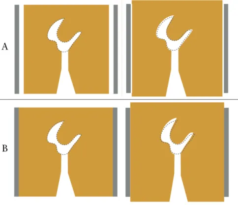
There are two types of investment materials, based on gypsum or phosphate. Gypsum-based investment is used for the conventional casting of gold alloys, while phosphate bonded investment is used for metal ceramic constructions and for pressable ceramics. The investment materials are also sensitive to the water/powder rations similar to the dental stone materials. Phosphate bonded investments undergo two dimensional changes – first there is a setting expansion and later a thermal expansion. Lloyd et al.[12] studied the setting expansion of different phosphate-based investments showing an expansion ranging from 0.78 to 3.3% depending on manufacturer, vacuum–mixing system and operator. Hutton et al.[13] studied the thermal expansion of phosphate bonded investments, finding expansions ranging from 1.01 to 1.71% depending on the manufacturer. The investment material is poured into a solid metal ring casting flask, and a ring liner is attached to the inside of the flask in order to allow expansion to the sides. The cylindrical openings allow expansion in the axial directions. This procedure is performed in order to allow a uniform expansion of the investment material (Figure 5).
Figure 5. A) Illustrates a casting flask with liner. This allows for a uniform expansion. B) Illustrates the results without liner.
Casting
During the investment there are two steps of expansion, first a setting expansion and later a thermal expansion. Depending on investment material and temperatures, a linear expansion as high as 1.7% may be obtained. If the casted alloy has a casting shrinkage of less than 1.7%, the casted crown could be too large[14]. The volume compensations are dependent on investment material, setting expansion, thermal expansion, application of liner, and the casting shrinkage of the alloy.
Post-processing
The conventional workflow for fixed prosthodontics results in either a pressed ceramic core/full anatomic construction or an alloy-based core. For the production of core-based frameworks porcelain is added in order to achieve an aesthetic construction; full anatomic (monolithic) ceramic constructions could be stained for characteristics (Figure 4).
PARTIALLY DIGITAL WORKFLOW
FIXED PROSTHODONTICS
Extraoral scanner
Figure 4 illustrates the conventional workflow for fixed prosthodontics in green, while the partially digital workflow is marked in red. For the partially digital workflow the same volume changes can be seen for the conventional impression, the stone model production and the die processing. It is also possible to scan the conventional impression directly, avoiding the stone model production. In order to design the intended construction digitally instead of using wax, the model needs to be digitised in an extraoral scanner, also known as a desktop scanner. There are two different types of extraoral digitising devices utilised to digitise dental stone models; optical and mechanical. The mechanical scanners collect data with a tactile method by touching the surface of the stone model, while the optical scanners employ a light source and cameras for triangulation. Accordingly, the optical scanner will be in focus.
Hardware
Extraoral dental laboratory scanners consist of a light source, receptor and a positioning system that orientate the object being digitised in different axes. The light source projects thin lines onto the object, when the light hits the surface it forms a profile; at the same time the receptor assesses the situation. In order to acquire a geometry with undercuts the object needs to be turned towards the light source, or vice versa[15]. The angle and distance between the light source and receptor are known, making it possible to measure objects
calculating the trigonometry, also known as triangulation[16]. The light source consists of either a laser or white light, the combination of light source and the reflective surface properties of the object being digitised are of importance for accuracy[17]. The extraoral scanners have a systematic digitising strategy because of the automatic surface projection, and the computer-controlled turntable that systematically coordinates the movement in collaboration with the receptor and the light source[18].
Performance
Several studies have tested the extraoral scanners utilised in dentistry for trueness and precision. Mandelli et al.[19] studied seven scanners utilising a standardised master model. Two of the scanners tested utilised lasers as a light source and the other five utilised structured light. All the tested scanners showed trueness values <20 µm with precision values ranging from 3.8 to 19.8 µm. Similar findings were shown by Luthardt et al.[20] with average trueness at 18.8 µm with a precision at 1 µm. Su et al. [21] compared intraoral scanning and extraoral scanning on five different reference models; their findings for the extra oral devices ranged from 8.67 to 24.33 µm (mean) with SD values ranging from 0.71 to 3.46 µm.
COMPLETELY DIGITAL WORKFLOW
FOR FIXED PROSTHODONTICS
Intraoral scanner
HistoryIn 1970, Francois Duret presented a concept of how to utilise scanning technologies from industry adapted for dentistry. His idea was to digitise preparations optically with a laser and then mill the final restoration, a process generally known as computer-aided design and computer manufacturing for dental restorations. The concept was further developed in the 1980s by Werner Mörmann and Marco Brandestini, who scanned their first patient in December the same year. Two years later (1982) the first handheld scanner for intraoral use was developed, and, by 1983, the first optical impression of an inlay was utilised. By 1985, the first functional intraoral scanner (IOS) was commercially available through CEREC 1 (Sirona, Bensheim, Germany)[22].
Light source
All intraoral scanners have the same goal, to digitise the size, shape and surface of a physical object into a geometrical virtual shape. This acquisition needs to be repeatable, reproducible and accurate. The IOS manufacturers try to achieve these goals with different hardware and software setups. There are two basic acquisition steps, firstly the scanner utilises some kind of optical light to capture the object. This light could either be active or passive. The passive light uses ambient light and is reliant on the texture of the object being digitised. The active light is either white, red or blue structured and is less reliant on
the texture of what is being digitised[16]. In the active technique, a luminous point is projected onto the object being digitised, this point is then captured by the receptor, making it possible to calculate the distance through triangulation. The surface acquisition consists of either images or a video (made from different frame rates). All these techniques are based on reflections from the surface of what is being scanned. For intraoral use there are many challenging surfaces such as blood, saliva, metals, composite surfaces, enamel, dentine, soft tissue and different light conditions depending on operator unit and office light[18]. Some manufacturers recommend the application of a powder on the surfaces before scanning. This procedure changes the reflective properties of the surfaces and simplifies the acquisition[23]. The powder application procedure could change the surface geometry
by up to 40 µm depending on how the powder is applied[24]. Another
strategy to overcome the reflective surfaces in the oral cavity is the use of polarizing filters[16].
Working principles
TriangulationAlso known as trigonometry, this is a measuring principle for optical systems to acquire the distance to the object being digitised. There are two types of triangulation, passive and active. The active method is the most utilised in dentistry because passive triangulation requires high contrast targets to work satisfactorily, and is thus not suitable for intraoral use[25]. In the active version a laser beam is deflected by a mirror, and the laser hits the surface and illuminates the object being digitised. A receptor registers the illuminated area; because of the fixed relation between laser and receptor a triangle is shaped and the distance to the object is possible to calculate. To speed up the process a series of patterns are projected onto the object instead of a laser dot. This is called the structured light method, consisting of an image of black and white lines that are projected onto the surface. If the scanned object is flat the receptor will register perfectly straight lines. If something is obstructing the lines the receptor will register deformed lines, thus making it possible to calculate the line deviations resulting in a surface topology[17]. Triangulation is not possible to conduct if the area being digitised is invisible to both, or either of, the laser or the receptor[26].
Confocal microscopy
This is a technique that acquires images on different focal depths. The lenses in confocal microscopy have a specific focal depth, and, when the digitised object is in focus, a 2D image is acquired. Then the camera is moved, thus a different area of the object will be in focus[16], resulting in several 2D images that are later software-processed. With mechanical systems adapting the lenses inside of the camera it is possible to acquire different focal depths faster, speeding up the acquisition process[26]. There are several other techniques utilised by different commercially available IOS devices.
Data processing
The digital data obtained from both intraoral scanners and extraoral scanners are represented by a point cloud; the digitising devices do not have the capability to acquire the whole surface of the object being digitised. Independent of light source and working principles, the virtual version of the digitised object will consist of points. The points represent the x, y and z coordinates of the digitised object.
Point cloud
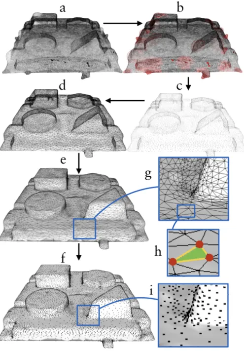
The density of the point cloud depends on the digitising device and technique, operator, scan time, and software algorithms utilised by the manufacturer, along with the complexity and reflective properties of the geometry that is being digitised and many other parameters[17]. Figure 6 illustrates a test object digitised with a Trios (2nd generation 3Shape, Copenhagen, Denmark) the files have been manipulated for educational purposes. Figure 6a illustrates a very dense and unprocessed point cloud instantly after the acquisition, during calculation of the 2D images to 3D files. Each 2D image has to overlap the previous one; this procedure is often described as a stitching or the best fit algorithm. The alignment process is an important feature necessary to achieve an accurate 3D file. During this process unwanted scatter will ascend, because of dust, saliva, blood, reflections, humidity on the scanner mirrors and so forth. In the process of this sampling, the software tries to preserve the measured features by assessing the points and profile of surrounding points[27]. Figure 6b illustrates with red dots areas where the software algorithm has reduced deviant points in the cloud[18]. At the same
time areas missing point data will be calculated by the software and a polygonisation process will ensure that the surface is closed[17]. The intraoral scanners are not designed to assume specific shapes such as spheres or cylinders, with the exception of some scanners that adapt their reconstruction algorithm for scanning implant scan bodies. There are several types of reconstructive polygonisations but they all have one thing in common; they are estimating the geometry of the missing points[27].
The points in the cloud go through a triangulation process that converts the points to a polygonal model, also known as a mesh (Figure 6d, e). The mesh image from Figure 6d is simpler to observe compared to the dataset in Figure 6a. In Figure 6e the mesh model has a surface added, making it even easier to distinguish the geometries on that specific model. The surface texture of virtual 3D files simplifies for observers distinguishing between different shapes. Modern IOS has the possibility to colour the digitised version of whatever is scanned, making it even easier to distinguish between blood, saliva, enamel, dentine, and so forth.
Post-processing
There are several post-processing procedures available for the scanned virtual object. A virtual model with a high-density point cloud (Figure 6a, b), could display the scanned object sufficiently, but the file would be very big and difficult to work with without capable computers. This is an especially important aspect for scanners utilised in dentistry, because the file usually needs to be either sent to a dental technician or to a chairside manufacturing unit. If the files are too big they could obstruct a convenient workflow. At the same time, it is equally important that the file is accurate and reliable as a reference for the rest of the workflow. In order to reduce the file size and at the same time keep the 3D object intact, the IOS manufacturers utilise a polygon-editing operation, reducing the number of polygons and simultaneously preserving the shape of the object[27] Figures 6b and 6c illustrate the reduction of point cloud data. Flat surfaces require fewer polygons then curved surfaces to retain their shape. Typically, the areas with large 3D curvatures will keep many polygons after the polygon-editing process, which is illustrated in Figures 6h and 6i[16].
Figure 6. a) raw cloud file b) unnecessary cloud data (red) is removed c) simplified point cloud d) each point is bound by a line configuring a mesh of triangles e) a surface is added to each polygon (triangle) g) triangle shape h) red dots are vertices (points) yellow lines are edges f) combined image of surfaces and points (vertices) i) example of the software algorithm that keeps points in 3D curves and reduces them on moderate geometries.
One example of this feature is the software algorithm for the Trios (3Shape, Denmark, Copenhagen) scanners. At the beginning of the workflow the operator needs to decide on what type of reconstruction the intraoral impression will be utilised. If the operator selects, for instance, a crown preparation on tooth 11, the software will make sure to keep as many polygons in that area during the polygon-reduction process as possible, meanwhile the rest of the virtual model will have a reduced number of polygons[28].
Scanning strategy
Extraoral scanners usually have a disclosed chamber, where the object is placed inside of the chamber and the scanner is isolated. In this way, the environment can be controlled for temperature and light conditions. Furthermore, the digitisation is systematic and computer-controlled. When scanning a dental stone model, the lab scanners have the possibility to acquire large areas of the model on each image[29]. For intraoral scanning, however, this procedure is not possible. Instead, the operator needs to sweep over the tissues to acquire the images. Because of the optical technologies utilised in different intraoral scanners, the operator needs to keep a certain distance ranging from 5-30 mm to the tissues being digitised because of variations in focal depth [16]. The IOS heads are often small, thus each acquired image is small. Because of the stitching process described earlier, all the small images need to be aligned in order to achieve a full-scale model[16, 30]. The alignment of each image is achieved by software algorithms identifying comparable point cloud data on the two images. The alignment process is challenging if the operator scans a totally flat surface. In contrast, the alignment is easier to achieve if the surface has a complex organic shape, like an occlusal surface of a molar.
Figure 7. a) Scanning procedure with a wiggling motion in the incisal region. b) Zig-zag motion scanning. c) Occlusal, buccal and lingual procedure. The scanning strategy, also known as scanning protocol or scan path, describes the acquisition process for intraoral scanning. One example would be to start scanning the occlusal surface in the maxilla from the posterior region to the incisal edge of the canine. Now the scanner is turned to acquire the buccal, incisal and palatal parts of the front teeth utilising a ‘wiggling’ motion (Figure 7a). When reaching the incisal part of the second canine the occlusal surfaces are acquired anterior to posterior. When reaching the last molar, the scanner tip is angled and the palatal and buccal surfaces are scanned respectively. Ender et al.[31] studied different scan strategies for full-arch scanning with different intraoral scanners, finding that the different strategies could impact upon the accuracy of the digital models up to almost 100%. Muller et al.[32] tested different scanning strategies. For one IOS system, they found that one of the three strategies (similar to the one described previously) had significantly better trueness and precision compared to other strategies.
Accuracy of intraoral scanners
In 2012, the International Organization for Standardisation published ISO 12836;2012 Dentistry - Digitizing devices for CAD/ CAM systems for indirect dental restorations – Test methods for assessing accuracy (the document was revised in 2015 to ISO 12836 2015). The ISO describes a standardised way to test the trueness and precision of primarily extraoral digitising devices in dentistry. Regarding the validation process of intraoral scanners there are currently no standards. As a consequence of this, most of the studies published with regards to this topic have non-comparable methods, reference models and trueness validations (reference scanner or computer metric measurement system)[33]. Even if some studies are comparable, the IOS manufacturers upgrade their hardware and software continuously, making it even more challenging to compare new scanners from the same manufacturer to older generation scanners with different hardware and software architecture[34]. As previously described, the software algorithms have an impact on the final digital model, so changes in the algorithms could possibly have important effects on the final result. A standardised way of testing the accuracy is needed in order to compare different intraoral scanning devices.
Ender and Mehl[35] compared conventional and digital impressions for full-arch scans in vitro. The authors rejected the hypothesis that the conventional and digital impressions would be equally accurate. The models made with vinylsiloxanether (VSE) material showed the highest accuracy. Ender et al.[36] continued to study the conventional and digital impressions in vivo and in vitro for full-arch models. Once again they had to reject the same hypothesis, but this time they found precision differences between the groups. The digital impressions were significantly less precise compared to the VSE impressions. They also found that the digital impressions performed better in the in vitro group compared to the in vivo group. However, there were no differences between the in vitro and in vivo group for the VSE material. Malik et al.[37] compared full-arch digital and conventional impressions for trueness and precision, and had to reject the hypothesis that there would be no difference between the groups. The conventional polyvinyl siloxane (PVS) impression
presented significantly higher accuracy in comparison to the digital impression. While there were statistical differences, they also found that all the tested impression methods showed accuracy levels to be less than 100 µm.
It is evident that the intraoral scanners have difficulties scanning full arches with high trueness and precision, even when studying different digital impression without comparison to the conventional impressions[33, 38-41]. Ender et al.[42] studied the precision of several IOSs on scanning quadrants (short arches). They found the different impression systems displayed significantly different levels of precision. They also concluded that all the digital impressions tested were capable of digitising the quadrant with clinically satisfying precision (threshold value was not presented). The found the mean trueness to be between 10 and 48 µm, with precision values ranging from 4 to 16 µm depending on manufacturer and impression technique. Nedelcu et al.[43] studied accuracy and precision of digital impression systems in vivo, with the conclusion:
“Intraoral scanners can be used as a replacement for conventio-nal impressions when restoring up to ten units without extended edentulous spans”.
Mangano et al.[44] studied trueness and precision for four IOSs on scanning two reference models with implant analogues, one partially edentulous and one totally edentulous. For the partially edentulous model the trueness ranged from 40.8 µm (SD 6.4) to 219.8 µm (SD 59.1), and, for the edentulous model, they presented trueness ranging from 55.2 µm (SD 10.4) to 204.2 µm (SD 22.7). The authors concluded that there was significant difference between the different IOSs, and this should be considered for the production of long-span prosthesis.
Computer-aided design
As seen in Figure 4, the next process in the digital workflow is computer-aided design (CAD). There are several dental-specific CAD software applications available, with different features and functions. Some of the features are universal for all types of dental
CAD software; these will now be described. The operator imports the scanned file either directly from an intraoral scan or indirectly from an extraoral scan. When the digital impression has finished with the previously described post-processing procedure, the virtual model is regarded as a master cast on which the restoration will be designed[45]. For the production of a one-unit full anatomic crown, the virtual master cast goes through a series of steps, usually starting with a clean-up stage where the operator can remove unnecessary mesh data. Regarding intraoral digital impressions, the unnecessary data could be information from the patient’s tongue, cheeks, lips or any other structure captured from the scanner that has no meaning in the production steps to follow. When the operator is satisfied with the clean-up, the process continues by defining the preparation finish line; this could be done manually, automatically or a combination of both[46]. The next step is the adaptation of a library tooth with pre-defined anatomy[47]. The operator places the tooth as close as possible to the desired shape, with possibilities to morph the tooth in different directions, size changes and other shape-defining procedures[48]. The desired shape will then automatically adapt to the previously defined finish line[45]. The process continues with an adaptation to the antagonist either manually, automatically or a combination of both[46, 47].
Design perimeters
The digital workflow for designing constructions virtually not only consists of the actual anatomical designs, but also of design parameters that adapt the construction for the manufacturing unit and the final reconstruction material. Comparable to the conventional workflow, the cement spacer is added to the virtual die digitally. The operator can choose dimensions and cement spacer combinations, for example a 25 µm spacer in the first mm from the finish line and another cement space set to 50 µm for the rest of the die. The cement spacer in the virtual design has the same purpose as for the conventional workflow, intended as clearance for the cement. The operator also has the possibility to apply clearance features to the antagonist and adjacent teeth in order to adapt the design to the virtual environment of that specific situation. Some other parameters that most types of dental CAD software enable are the design parameters for edge
thickness, edge angles, undercut adaptation, milling diameter, minimal thickness warnings and connector dimensions (for fixed partial dentures). Depending on what material and manufacturing unit the reconstruction is going to be produced in, these parameters will vary. One example is the manufacturing parameters of IPS e-max CAD (Vivadent Ivoclar, Liechtenstein Schaan,) in the dental CAD software Exocad (Exocad GmbH, Germany, Darmstadt)[49]. Table 1 shows the recommended parameters from the manufacture for the production of crowns and bridges made from their lithium disilicate material. The parameters are defined for that specific dental CAD software (in this case Exocad), preparing the designed construction for the computer aided manufacturing (CAM) step to follow and post-production processes such as the crystallisation process. Similar parameters can be found from other manufacturers.
Table 1. Exocad production parameters for designing and manufacturing IPS e.max CAD constructions.
Software description G ap thickness of cement A dditional distance
x/y Beginning of cementM inimal thickness H orizontal crown margin A ngle A ngled crown margin C ross section of connector Single crown anterior 0.06 mm 0.02 mm 1.20 mm 1.00 mm 0.20 mm 65° 0.10 mm –
premolar 0.06 mm 0.02 mm 1.20 mm 1.00 mm 0.20 mm 65° 0.10 mm – molar 0.06 mm 0.02 mm 1.20 mm 1.00 mm 0.20 mm 65° 0.10 mm – primary tele 0.06 mm 0.02 mm 1.20 mm 1.00 mm 0.20 mm 65° 0.10 mm – anterior 0.06 mm 0.02 mm 1.20 mm 1.20 mm 0.20 mm 65° 0.10 mm 16 mm² posterior 0.06 mm 0.02 mm 1.20 mm 1.50 mm 0.20 mm 65° 0.10 mm 16 mm² anterior 0.06 mm 0.02 mm 1.20 mm 1.20 mm 0.20 mm 65° 0.10 mm 16 mm² posterior 0.06 mm 0.02 mm 1.20 mm 1.50 mm 0.20 mm 65° 0.10 mm 16 mm² M illing parameters A nticipate milling Y es D iameter 1.31 mm IPS e.max C A D (C rown/bridge)
C ement spaces External surfaces
M inimum connector area/ 2 crowns M inimum connector area / 1 pontic C onnector settings
Computer-aided manufacturing
Figure 4 illustrates the next process for digital dentistry, namely the CAM step. In the production processes for dental application, computerised manufacturing is divided into two main groups, subtractive and additive. The subtractive group consists of machines that remove material from a solid body with rotating tools, in order to attain the designed shape. The additive group consist of machines that add material layer by layer, solidifying each layer or the end-product in order to attain the designed shape.
Figure 8. Illustration of the machining nomenclatures correlated to subtractive manufacturing.
Subtractive manufacturing
When the operator has completed the design procedure, the file will be processed by CAM software. The CAM software will calculate computerised numerical controlled (CNC) machining tool paths also known as G-codes[50] for the designed reconstruction. The tool paths consist of the object’s profile data, and also contains the selection of cutting tool type for different parts of the design as well as the rotational speed of the cutting tool[18, 29, 51]. The G-code also contains information regarding cooling sequences during the manufacturing process. There are many subtractive manufacturing units available for dental application, ranging from small units for chairside use to machines for industrial use. A unit generally consists of a machine frame, a tool holder, a workpiece holder and rotational axis ranging from 3-5 axis[51]. The size and shape of the tool tip in correlation to the tool path will determine how closely the object will be manufactured to the designed geometry (Figure 8). If the tool tip has a high diameter with steps between the tool paths, the manufactured object will end up with a rough surface[18]. In mechanical engineering the surface roughness created by CNC machining is referred to as tool path cusp height[52]. To achieve a smooth surface the tool paths need to be close to each other and the diameter of the cutting tool needs to be as small as possible.
Figure 9. Illustration of drill compensation. The dotted lines illustrate the intended design, because of the tool dimension limitations the CAM procedure need to compensate in sharp areas.
The tools utilised for cutting the bulk material will be subject to wear; when the sharpness or abrasiveness is reduced, the surface roughness of the manufactured object will be affected. The wear of the tools utilised during the fabrication process is correlated to the hardness of the bulk material. If the bulk material is soft, the tools will be less affected[53]. Most dental CAM machines have the ability to change tools during the manufacturing process. Typically, the process starts with a highly abradant tool that has the ability to remove a high amount of material in the periphery – as the tool paths get closer to the intended design, the machine changes tool, to a smaller diameter. If the prepared tooth has sharp edges with an edge radius smaller than the smallest diameter of the machining tool, the design software will have to compensate for this in the design, also known as drill compensation (Figure 9).
For the milling of yttrium-stabilized tetragonal zirconia polycrystals (Y-TZP), or metallic materials, the bulk material could either be pre-sintered (green stage) or densely pre-sintered. Both bulk versions have their advantages and disadvantages – as previously described, milling hard materials wears out the tools, something that would take place with the densely sintered version. Furthermore, the pre-sintered version
needs to go through a sintering process, leading to a shrinkage. For the pre-sintered version, the CAM software needs to compensate allowance for the shrinkage before the manufacturing[54].
Accuracy of subtractive manufacturing
Kirsch et al.[55] studied the manufacturing trueness for four different milling units, by designing different single unit constructions that were later manufactured in dental CAM machines. The manufactured objects were compared to the designs, a process also known as reverse engineering. They found an overall trueness in the range of 25,7 µm ± 9,4 µm to 48,7 µm ± 23,3 µm. They concluded that the five-axis machines showed highest trueness, because these milling devices had the ability to process areas that were difficult for machines with less axes to reach. Bosch et al.[56] used a similar approach to investigate the dimensional accuracy on milled reconstructions. Their findings for trueness ranged from 42 to 76 µm in the occlusal areas and 41 to 96 µm in the inner areas (surface close to the preparation). They concluded that a five-axis milling machine accomplishes accurate reconstructions, and that a small diameter rotary tool resulted in more accurate milling. In a review based on 70 studies by Papadiochou et al.[57] marginal adaptations of different CAD/CAM technologies were evaluated. Their findings suggest that the majority of dental restorations produced with CAD/CAM presented marginal
discrepancies ≤120 µm.
Additive manufacturing
HistoryAlso known as rapid prototyping, additive manufacturing (AM) is a manufacturing technology invented by Charles ‘Chuck’ Hull in 1984[58]. The invention describes a production process of producing solid plastic models by successively applying thin layers of curable material on a build plate. The build plate is then moved away from the liquid surface by a thickness of one layer and the layer-curing process starts all over again; this production process was named stereolithography (SLA). Hull also explains in his patent that the SLA process helps the operator to avoid the tool path processes otherwise necessary in subtractive manufacturing. He also describes the invention as a time- and material-saving process for part production.
Instead of weeks and months of production time, the part can be produced rapidly. The following citation describes the purpose of the patent;
“Hence, the stereolithographic apparatus of the present inven-tion satisfies a long existing need for a CAD and CAM system ca-pable of rapidly, reliably, accurately and economically designing and fabricating three-dimensional plastic parts and the like.”
The AM technology has been utilised just as Hull hoped in his patent, as the manufacturing sector has been using it for rapid-design purposes ahead of mass production. Meanwhile, one of the significant advantages with the additive technique has been the ability to produce almost any shape. This includes generic, biological shapes such as human organs. Thus, the technique has been adopted by scientists, medical doctors, artists, architects and other professionals in need of generic designs[59]. According to the Wholers report[60] from 2018, 135 companies around the world produced and sold AM systems in 2017. They also reported an increase of nearly 80% of sold metallic AM systems in 2017 (estimated to 1768 units). According to the same report from 2017[61], nearly half of the AM businesses use polymer manufacturing units. Currently, there are several versions of AM for light curable resins.
Product development
The product development for industrial AM processes starts with a design concept. During this process the operator needs to decide whether the concept is going to be manufactured subtractively or additively. The concept is later visualised and designed through CAD software – if SM is going to be used the designer needs to take this into account; as previously stated the SM technology has some limitations regarding design features because of the tactile five-axis movement technology. For AM production the operator has almost total design freedom. When the CAD is finished, the file goes through a software process preparing it for manufacturing. The SM units use the G-code preparation, while, for AM production, the pre-production process consists of a slicing algorithm that slices the 3D object into profile layers with a thickness defined by the operator with limitations of the
The STL file
The original SLA approach to build parts was based on building walls (the profile of the object). This led to two types of problems: 1) weak structural strength because the object was hollow, and 2) failures in the layer-to-layer adhesion. Further developments of the SLA patent led to the invention of the STL file, also known as Standardised Tessellation Language file. The file structure describes the surface geometry of a design by triangulating the surface – the more triangles that are formed the better surface resolution. Data points representing the triangle coordinates in each slice are then transferred to the AM system for layering, making it possible to manufacture objects that are not only produced by a thin wall[62].
Fabrication principles
The operation of all AM systems is based on the same principles; the fabrication of parts layer-by-layer without the need for manufacturing tools. Furthermore, there are three basic fabrication stages, starting with the selection of build parameters, where the operator selects layer height (thickness) and placement of supporting structures so that the object being produced has limited movement and to support overhangs from distortion. The next phase consists of the manufacturing of the part; the SLA system utilises a light curable liquid resin, curing source utilising ultra violet (UV) light and an elevation platform. The three parts are coordinated in the fabrication process. When the UV light strikes the polymer surface, it cures one layer of polymer. The first layers adhere to the elevating platform, the elevator is lowered by one layer’s height. A new layer of uncured resin is then recoated and polymerised with UV light, forming another layer on top of the previous layer. This process continues layer-by-layer until the part fabrication is completed[15]. The third and final stage is the post-production phase, consisting of cleaning, surface enhancements, and post-curing[15, 63]. The original patent for SLA described a laser as light source; however, today there are other light sources available. One system often seen for dental applications is the Digital Light Projection (DLP) technology, the light source in this case is a projector utilising UV light to cure the resin. For the production of metallic components, the fabrication principles are the same. Instead of a liquid light curable resin the AM of metallic components utilises a
fine metallic powder. One thin layer of the powder is coated onto the elevation platform, the object layers are then either melted (Selective Laser Melting, SLM)[64], sintered (Selective Laser Sintering, SLS for polymers, or Direct Laser Metal Sintering, DLMS) or merged utilising either a high-energy laser, electron beams (Electron Beam Melting, EBM) or some kind of binder[65]. The elevation platform is then lowered by one layer’s height and the process starts all over again. The post-production phase for metallic components consists of cleaning, sintering or heat treatment and surface enhancements.
Additive manufacturing applications in dentistry
The limitation of use for dental application is correlated to materials that are biocompatible or bioinert; the continuing material development from additive manufacturers enables more dental applications. For the production of polymers, AM technologies are being used for the fabrication of dental models[66, 67], provisional reconstructions[68], surgical guides[69], occlusal devices[70], prosthetic metallic frameworks for both fixed[71] and removable prosthodontics[72]. For metallic applications AM technologies are being used for prosthetic frameworks in Ti-6Al-4V alloys, and Co-Cr. The metallic AM systems also have the ability to manufacture surgical Ti-6Al-4V alloy implants individualised for patient requirements[65]. For the additive production of metallic components, the dental field has predominantly utilised Direct Metal laser sintering and Selective Laser Melting. Both of these technologies are powder based, the main difference between the technologies is that the first one sinters the powder particles and the second melts it. The SLS technology has a limited use in dentistry today, primarily because of the higher surface roughness on the end products compared to SLA and DLP manufacturing. The SLS technology does not require support structures and the technology has the ability to manufacture tough objects with greater material properties compared to objects manufactured through SLA (Table 2).
Table 2. Table illustrating different additive technologies utilised in dentistry today.
Accuracy of additive manufacturing of polymer constructions
Salmi et al.[66] studied the accuracy of medical polymer models of human craniums, comparing three different AM technologies. They found that the model errors were in the range of 0.18% to 0.80% in deviation when compared to the original CAD model. Turbush et al.[73] compared the accuracy of implant placement by studying three different types of surgical implant guides made with SLA utilising cone beam computerized tomography (CBCT) as base. They found that the mean angular deviation was 2.2 ± 1.2 degrees, and the mean linear deviation was 1.18 ± 0.42 mm at the implant neck. They could not identify any significant differences among the guides, and they concluded that the average linear deviation was 1 mm between planned implant placement and the actual placement. Arnold et al.[74] studied the accuracy of producing removable partial dentures utilising five different methods: conventional, SLA (castable), SLM (direct) and two types of subtractive (direct and castable). They found that both of the AM groups exhibited the
highest discrepancies, whereas the subtractive group showed the best results. Fathi et al.[75] studied the marginal and internal fit of wax patterns produced by conventional, subtractive, and additive methods, finding that the additive wax patterns were more accurate (36 ± 5 µm) than the conventional (141 ± 31 µm) method. Other authors have compared marginal and internal fit on printed wax patterns to conventional and milled constructions, with differing results. Homsy et al.[76] concluded that the subtractive method of wax pattern fabrication presented better marginal and internal fit compared to the conventional and additively manufactured groups. Yau et al.[77] compared additive and subtractive manufacturing of models for orthodontic planning. They concluded that the subtractive five-axis machine produced models with an accuracy of 10-20 µm while the additive group had an accuracy ranging from 30-50 µm.
Build orientation
For the SLA approach different types of polymers are utilised. Ideally, the materials consist of monomers, comonomers and reactive oligomers. The resins should have a viscosity suitable for AM (not too high or too low). The balance between type of monomers, photo initiator concentration and curing intensity/speed gives the end product different properties[78]. Tahayeri et al.[68] studied additively manufactured provisionals for crown and bridge applications. They found that the provisionals had an elastic modulus close to 2000 MPa, comparable to conventional provisonals. They also found that the manufacturing orientation of the test objects affected the accuracy. When manufacturing the objects at a 90-degree orientation the length accuracy was 2% on average, while the thickness had a 20% error. When the orientation was changed to 0 degrees the thickness accuracy was reduced to 10% error. They also found that, depending on which colour setting was selected, they could see sample thickness variations of 41.5%. Alharbi et al.[79] studied the build angle and support structures of full anatomic polymer crowns made through SLA. They concluded that the build orientation should be 120 degrees with thin supports. Depending on support thickness and build orientation, the maximum deviation and minimum deviation ranged from 548 µm (210°-thick supports) to -548 µm (270°-thick supports). Osman et al.[80] also studied the correlation between
accuracy and build angle, with a similar approach as the previous study. They utilised a DLP system for production, concluding that the highest dimensional stability was achieved at 135 degrees.
Accuracy of additive manufacturing of metallic constructions
Huang et al.[81]studied the marginal fit of metal ceramic CoCr crowns manufactured with SLM. They compared the SLM group with a conventionally casted group, finding that mean marginal discrepancies of 75.6 µm ± 32.6 for the SLM group and 91 µm ± 32.1 for the casted CoCr group. They concluded that the marginal Co-Cr metal ceramic crowns had better marginal fit in comparison with the casted Co-Cr crowns. They also found that the SLM group had less accurate occlusal fit compared to the casted group. Kim et al.[82] compared the marginal and internal gaps of Co-Cr copings fabricated with SLM, subtractive manufacturing and conventional casting. Their findings showed that the mean of the marginal discrepancies for the SLM group was 239 µm ± 126.0 while the lost wax casted group had a marginal discrepancy of 91 µm ± 80.9 and the subtractive group 60 µm ± 20.6. Their findings also suggested that the SLM group had a higher occlusal gap compared to the other groups, when compared to the subtractive group, the occlusal gap was 4 times larger for the SLM group. Bae et al.[83] studied the production accuracy of subtractive manufacturing and two additive methods; SLM, and SLA. Their findings suggested that both of the additive systems had higher accuracy than the subtractive group. Örtorp et al.[84] studied the fit of Co-Cr three-unit frameworks, comparing four different manufacturing techniques. Two of the groups consisted of a milling group and a DLMS group. The found that the DLMS group had the lowest mean gap value (<100 µm).