http://www.diva-portal.org
Preprint
This is the submitted version of a paper presented at 22nd IEEE International Requirements Engineering
Conference (RE'14), Karlskrona, Sweden, from the 25th to the 29th of August, 2014.
Citation for the original published paper:
Zhou, J., Lundqvist, K., Lönn, H., Karlsson, D., Liwång, B. (2014)
Towards Feature-Oriented Requirements Validation for Automotive Systems.
In:
N.B. When citing this work, cite the original published paper.
(c) 2014 IEEE. Personal use of this material is permitted. Permission from IEEE must be obtained for
all other users, including reprinting/ republishing this material for advertising or promotional purposes,
creating new collective works for resale or redistribution to servers or lists, or reuse of any copyrighted
components of this work in other works.
Permanent link to this version:
Towards Feature-Oriented Requirements Validation
for Automotive Systems
Jiale Zhou
1, Yue Lu
1, Kristina Lundqvist
1, Henrik L¨onn
2, Daniel Karlsson
2, Bo Liw˚ang
3 1School of Innovation, Design and Engineering, M¨alardalen University, V¨aster˚as, Sweden2
Advanced Technology and Research, Volvo Group, G¨oteborg, Sweden 3
Swedish Radiation Safety Authority (SSM), Stockholm, Sweden 1{zhou.jiale, yue.lu, kristina.lundqvist}@mdh.se
2{henrik.lonn, daniel.b.karlsson}@volvo.com 3
bo.liwang@ssm.se
Abstract—In the modern automotive industry, feature models have been widely used as a domain-specific requirements model, which can capture commonality and variability of a software product line through a set of features. Product variants can thus be configured by selecting different sets of features from the feature model. For feature-oriented requirements validation, the variability of feature sets often makes the hidden flaws such as behavioral inconsistencies of features, hardly to avoid. In this paper, we present an approach to feature-oriented requirements validation for automotive systems w.r.t. both functional behaviors and non-functional properties. Our approach first starts with the behavioral specification of features and the associated require-ments by following a restricted use case modeling approach, and then formalizes such specifications by using a formal yet literate language for analysis. We demonstrate the applicability of our approach through an industrial application of a Vehicle Locking-Unlocking system.
Index Terms—feature-oriented requirements modeling; model-based requirements validation; eTASM; RUCM; software prod-uct lines; systems functional behaviors and non-functional prop-erties
I. INTRODUCTION
With the growing maturity and standardization of the au-tomotive domain, requirements specifications for auau-tomotive systems tend to center around the concept of feature models. Feature models [1] are proposed to capture the commonality and variability within a software product line by using features, between which there are relations and constraints. Further, a feature [2], [3] is a logical unit of functionality comprehensible to end-users, which consists of the requirements (i.e., the feature requirement hereafter) associated with the feature and the corresponding behavioral specification (i.e., the feature behaviors hereafter). A product can be configured by selecting a set of features (i.e., the feature set hereafter) from a feature model. The validity of a feature set refers to two situations: 1) one is from the structural perspective, i.e., the selected features should conform to the constraints defined by the feature model and, 2) the other is from the functional perspective, i.e., no un-desirable behaviors exist between two or more (as integrated) feature behavioral specifications. In order to increase the confi-dence of the validity of the feature set, several feature-oriented requirements validation techniques [3], [4], [5], [6], [7], [8] have been developed. However, it is well recognized that with
the increasing size of feature models, the inherent variability of the feature sets leads to an inevitable issue that the hidden flaws of features are difficult to avoid [9]. Especially, the feature interaction problem (referring to the situation that two or more features exhibit unexpected behaviors) cannot be detected when the features are used in isolation.
As the unexpected behaviors can result in uncertainties and even hazards of automotive systems, adequate efforts on de-tecting the unexpected feature interactions thereby must be ap-plied in the early stages of the pertaining development process. In the literature, there are many examples [7], [10], [11] where the process starts with translating the natural language specifi-cation (NLS) of a feature into a formal language specifispecifi-cation (FLS) of the feature behaviors, and then the requirements validation is performed based on the generated formalisms. To our best knowledge, the main drawbacks of using NLS lie in: 1) ambiguities in the NLS cause imprecise definitions and even wrong understanding of the feature behaviors and, 2) the direct translation from the NLS to a FLS tends to be very costly and, 3) the NLS hinders to a large extent the possibility of performing automatic feature-oriented requirements validation. To challenge the feature interaction problem and make up for the deficiency in the current practice, in this paper we propose a model-based approach to feature-oriented require-ments validation. To be specific, our approach firstly specifies features by using an informal yet restricted natural language (from scratch) without losing ease of use, and then formalizes a set of executable models based upon the aforementioned intermediate specifications to perform the requirements vali-dation. The approach is comprised of four steps as follows:
• Feature Specification specifies the behaviors and
re-quirements of features by following the restricted use case modeling (RUCM) approach [12], which adopts a generic use case template and several restriction rules to reduce ambiguity and facilitate further analysis.
• Feature Behaviors Formalization formalizes the feature behaviors in terms of a formal yet literate specification us-ing the extended Timed Abstract State Machine (eTASM) language [13], which generates executable models for analysis.
• Feature Requirements Formalization models the
ture requirements by using the Observers technique [13] in eTASM for validation purpose.
• Feature Validation performs three kinds of model-based validation checking to detect the hidden flaws in the se-lected features, including Logical Consistency Checking, Coverage Checking, and Model Checking.
We also demonstrate the applicability of our approach through an illustration application, and the remainder of this paper is organized as follows: An introduction to the background knowledge is presented in Section II. Section III introduces the illustration application i.e., the Vehicle Locking-Unlocking (VLU) system. Our approach to feature-oriented requirements validation is described and illustrated by using the VLU system in Section IV. Section V discusses the related work, and finally concluding remarks and future work are drawn in Section VI.
II. BACKGROUND
In this section, we briefly introduce the RUCM ap-proach [12] and the formal specification language eTASM [13] used in our approach for a better understanding.
A. Restricted Use Case Modeling
The restricted use case modeling (RUCM) [12] is a use case modeling approach that extends the UML [14] use case diagram by proposing a use case template and 26 restriction rules for reducing ambiguity and easing automated analysis. In our work, we specify features by populating the proposed use case template and following the restriction rules. In order to meet our needs, we make two slight modifications to the tem-plate. First, for the purpose of traceability, the use case name is required to follow the form of FeatureName UseCaseName or merely FeatureName. Second, the Basic Description entry is replaced by Feature Requirement which specifies the re-quirement that the feature is associated with. Figure 1 shows the modified template and the brief explanation for each entry.
Fig. 1. The modified use case template of RUCM.
The feature behaviors are specified via use case flows, which are composed of one basic flow and one or more alternative flows. The basic flow specifies the main execution path in terms of a sequence of steps and a postcondition. Alternative flows specify execution branches when deviations occur somewhere in the reference flow that can be the basic flow or an alternative flow. There are three types of alternative flows: a specific alternative flow refers to a specific step in the reference flow; a bounded alternative flow refers to more than one step in the reference flow; a global alternative flow refers to all steps in the reference flow. RUCM defines 16 restriction rules to constrain the use of natural language, as shown in Figure 2. A set of keywords are also defined in the other 10 rules to specify control structures. For example, the keyword VALIDATES THAT (as shown in Figure 4) is used for condition checking. In particular, if the condition evaluates to be true, the current flow continues, otherwise an alternative flow will be executed. The detailed description of all the restriction rules and keywords are provided in [12].
Fig. 2. The rules of RUCM to constrain the use of natural language.
B. The Extended TASM Language
eTASM [13] is a formal language for the specification of safety-critical systems, which extends the Timed Abstract State Machine (TASM) language [15] with the Observer and Event constructs. eTASM inherits the easy-to-use characteristic from TASM, which is a literate specification language understand-able and usunderstand-able without extensive mathematical training. An eTASM model consists of three parts – an environment, a set of machines, and a set of observers. The environment defines the set and the type of machine variables which machines can monitor or control, and the set of named resources which machines can consume. An machine consists of a set of monitored variables (which can affect the machine execution), a set of controlled variables (which machines can modify), and a set of machine rules. The set of rules specify the
machine execution logic in the form of “if condition then action”, where condition is an expression depending on the monitored variables, and action is a set of updates of the controlled variables. We can also use the rule “else then action” which is enabled merely when no other rules are enabled. A rule can specify the annotation of the time duration and resource consumption of its execution. The duration of a rule execution can be the keyword next that essentially states the fact that time should elapse until one of the other rules is enabled. The observers will monitor the events triggered by the execution of machines, and each observer represents one correctness property of interests that should be satisfied by the proposed system. In the eTASM language, four types of events can be triggered: The ChangeValueEvent type is triggered by a specific eTASM environment variable whenever its value is updated, the ResourceUsedUpEvent is triggered by the case whenever the resource of the application is consumed totally, and the RuleEnableEvent and RuleDisableEvent are triggered whenever the corresponding eTASM rule is enabled or disabled, respectively. An observer is made up of an ObserverEnvironment, a Listener, and an Observation. The ObserverEnvironment defines a set of observer variables and an EventsFilter that filters out irrelevant event types to the observer. The Listener specifies the expected events sequence following the syntax and semantics of regular expression. The Observation indicates the monitoring result, i.e., whether the correctness property monitored by the observer is satisfied.
eTASM describes the basic execution semantics as the computing steps with time and resource annotations: In one step, it reads the monitored variables, selects a rule of which condition is satisfied, consumes the specified resources, and after waiting for the duration of the execution, it applies the update set instantaneously. During the execution, eTASM triggers events whenever possible. The events sequence is monitored by observers. Once an expected sequence is ob-served, the corresponding monitoring result will be concluded. As a specification language, eTASM supports the concepts of parallelism (which stipulates that eTASM machines are executed in parallel) and hierarchical composition (which is achieved by means of auxiliary machines which can be used in other machines). There are two kinds of auxiliary machines - function machines that can take machine variables as parameters and return an execution result, and sub machines that can encapsulate machine rules for reuse purpose [15]. Communication and interaction between machines can be achieved by defining corresponding environment variables.
III. ILLUSTRATIONAPPLICATION
In this section, we describe a simplified Vehicle Locking-Unlocking (VLU) system, as a running example to illustrate our approach in this work. The proposed VLU system aims to replace the mechanical key, as a control access to a vehicle, and it follows a common pattern in feature-oriented require-ments specification: The basic functionality is encapsulated as an individual feature, and additional/optional enhancements are specified as features that provide the increments in
func-tionality. Specifically, such features are Central Locking (CL), Auto-lockout (AUL) and Anti-lockout (ANL). Figure 3 shows the features of the VLU system in the form of technical feature model tree which is presented in EAST-ADL [16].
Central Locking (a basic feature) locks and unlocks all the doors of the vehicle upon receipt of a command from the user key fob.
Auto-lockout (an optional feature) locks all the doors of the vehicle when a timeout expires after the vehicle has stopped. It provides a theft protection in case that the driver forgets locking the doors manually.
Anti-lockout (an optional feature) enables unlocking of the doors while a key is in ignition after the vehicle has stopped, of which purpose is to prevent the driver from being locked out of the vehicle.
In simple applications such as the one above, it is possible to manually analyze the interactions between features for re-quirements validation. However, the real-world systems often have a large number of complex features, making the per-taining manual analysis extremely time-consuming and error-prone. The main motivation for our approach is to provide a semi-automatic technique for feature-oriented requirements validation for automotive systems, by performing undesirable feature interaction analysis. In the rest of the paper, we will use the aforementioned simplified application to illustrate our approach for features modeling, features specification, and auto-detection of undesired interactions.
Fig. 3. The technical feature model tree of the VLU system.
IV. THEAPPROACH TOFEATURE-ORIENTED
REQUIREMENTSVALIDATION
In this section, we will introduce our approach that ad-dresses the issue of formalizing and validating feature-oriented requirements specifications. In general, our approach is con-ducted in four steps as follows:
• Step 1: Feature Specification specifies the behaviors and requirements of features by using the RUCM use cases, which facilitates the further analysis.
• Step 2: Feature Behaviors Formalization formalizes the feature behaviors using the eTASM machines, which are executable analysis models.
• Step 3: Feature Requirements Formalization formal-izes the feature requirements by using the eTASM Ob-server technique.
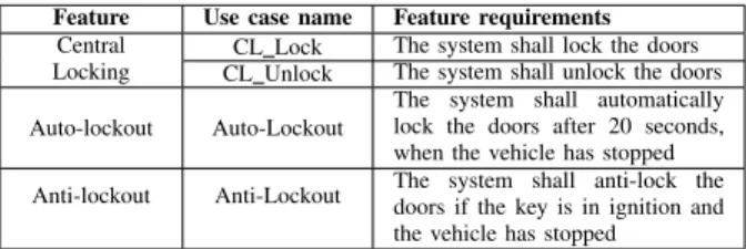
TABLE I
THE IDENTIFIED USE CASES AND CORRESPONDING FEATURE REQUIREMENTS.
Feature Use case name Feature requirements Central
Locking
CL Lock The system shall lock the doors CL Unlock The system shall unlock the doors
Auto-lockout Auto-Lockout
The system shall automatically lock the doors after 20 seconds, when the vehicle has stopped Anti-lockout Anti-Lockout The system shall anti-lock thedoors if the key is in ignition and
the vehicle has stopped
• Step 4: Feature Validation performs three types of checking by using model-based analysis techniques, to detect the hidden flaws in feature specifications.
We will go into details about each step by introducing the adhering sub-steps and show a running example to il-lustrate our approach. Specifically, Section IV-A introduces feature specification using the RUCM use cases. Section IV-B and Section IV-C discuss modeling of the behaviors and requirements of features respectively. Section IV-D presents the analysis and results of feature validation of the VLU system.
A. Feature Specification
The Feature Specification step describes the features of a system in a restricted natural language, which can facilitate the further transformation from an informal specification to the formal one, for the purpose of validation. In this step, each feature will be specified by following the RUCM approach, and there are two sub-steps in our work as follows:
• Step 1.1: Use Cases Identification: Since a feature
captures a set of cohesive functionalities in the form of requirements and corresponding behaviors, it is therefore necessary to split the functionalities and identify the possible use cases based on the expert’s understanding of the feature.
• Step 1.2: Use Cases Specification: Use cases are spec-ified by filling the RUCM template using a restricted natural language. In order to facilitate the further analysis, some predefined restriction rules must be followed. In the VLU system, there are three selected features i.e., CL, AULand ANL (as introduced in Section III). The specification of features, as an example, is illustrated by applying the proposed steps to the CL feature. To be specific, since the CL feature describes two opposite functionalities, two use cases can be thereby identified in terms of CL Lock and CL Unlock, as shown in Table I. Figure 4 and Figure 5 describe the filled use case templates of CL Lock and CL Unlock, respectively. B. Feature Behaviors Formalization
This step is to analyze the specified RUCM templates and formalize the corresponding feature behaviors by using eTASM models which are executable simulation models for analysis. The Feature Behaviors Formalization step contains four sub-steps:
Fig. 4. The CL Lock use case of the CL feature.
Fig. 5. The CL Unlock use case of the CL feature.
• Step 2.1: System Constituents Identification extracts
the relevant system constituents referred in the RUCM use cases and specifies them in eTASM machines.
• Step 2.2: Constituents Interaction Identification
identi-fies the interactions between different system constituents referred in the RUCM use cases and specifies them in eTASM environment variables.
• Step 2.3: Machine Rules Specification analyzes the possible states of identified machines and specifies feature behaviors by using a set of eTASM machine rules.
• Step 2.4: Property Annotation adds non-functional property annotations to the relevant eTASM machines. 1) System Constituents Identification: The identification of the system constituents from the use cases is of importance in the process to formalize the behaviors of the proposed system and model the scenarios for model-based validation. In order to do so, we recommend the following two tasks:
• External Constituents Identification: Use case actors are considered as external constituents which interact with the proposed system. The external constituents will be modeled to simulate the execution scenarios.
• Internal Constituents Identification: Each use case is
considered to be an internal constituent, making up the proposed system. The internal constituents will be mod-eled to simulate the proposed system.
In this step, a list of eTASM machines w.r.t. the identified constituents is defined for the VLU system, as shown in Table II.
2) Constituents Interaction Identification: Two types of interaction between the sending constituent (i.e., sender) and receiving constituent (i.e., receiver) are considered in our
TABLE II
THE ETASMMACHINES IDENTIFIED FOR THEVLUSYSTEM. Machine Quantity Category Brief Description
KEY FOB 1 External model the key fob’s behavior LIGHT 1 External model the light’s behavior DOORS 1 External model the behavior of doors IGNITION 1 External model the behavior of ignition
VEHICLESPEEDSENSOR 1 External model the behavior of vehicle speed sensor
CL LOCK 1 Internal lock doors
CL UNLOCK 1 Internal unlock doors
AUTO LOCKOUT 1 Internal lock doors when timeout expires ANTI LOCKOUT 1 Internal anti-lock doors if key is in ignition
approach:
• Data Transmission Interaction (DTI)represents that data (such as the state information and various sensor values) are transferred from the sender to the receiver, which are modeled as eTASM environment variables. The variables are named as sender datatype which denotes the trans-ferred data. Line 2 in Figure 7 shows an example.
• Data Modification Interaction (DMI) represents that the
data of the receiver is directly changed by the sender, which are modeled via directly modifying the value of the receiver’s environment variable. The variables are named in the form of receiver datatype, which denotes the modified data. One example can be found in Lines 9 and 10 in Figure 7.
Since RUCM requires the interaction between a system and an actor to be clearly described without omitting some information about its sender and receiver, it is therefore easy to identify interactions between constituents from the use case models. Figure 6 shows the identified interactions in our VLU system, which are twelve interactions. Further, the solid lines represent DTIs, and the dashed lines represent DMIs.
Fig. 6. The identified interactions between constituents in the VLU system.
3) Machine Rules Specification: The restricted use case flow sentences (e.g., in basic and/or alternative flows) can to a large extent facilitate the transformation from use case models to analysis models [17]. Based on the sentences specified in use case flows, we recommend the following sub-steps to specify the eTASM machine rules:
• Identification of possible states of the corresponding constituent: The possible states of a constituent can be identified via analyzing the adjectives and verbs in the use case flows. A user-defined type is used to represent the
possible states, and a state variable is defined to denote the current state of the constituent.
• Identification of the transition conditions of states: The conditions of a certain machine rule are given, according to the pertaining values of the state variables and the transition conditions.
• Identification of the actions when the system enters a specific state: The actions of machine rules are specified, based on the behaviors of a constituent and the next possible state.
In our VLU application, there are five external constituents and four internal constituents under consideration, as shown in Table II. The KEY FOB machine simulates the behaviors of a user’s key fob. This machine has two possible states lock and unlock, in which the lock/unlock state denotes that the lock/unlock command is sent to the proposed VLU system. The LIGHT machine simulates the behaviors of the vehicle light, which has two states i.e., the flashed state and the off state. The flashed state denotes that the light flashes for several times. The DOORS machine simulates the behaviors of the vehicle doors, which has three possible states open, close and locked. The IGNITION machine simulates the behaviors of the vehicle ignition, which has two possible states haskey and nokey. The VEHICLESPEEDSENSOR machine simulates the behaviors of the vehicle speed sensor, which has two possible states still and running.
The CL LOCK machine, as shown in Figure 7, models the CL Lock use case. The machine has two possible states in terms of idle and lockdoor. The Rule ReceiveCommand represents that the system receives the lock command from the key fob. The Rule Locking represents that the system locks the doors. The Rule Idle keeps the machine alive and represents the system is idle. The CL UNLOCK machine has similar rules, which will not be introduced for simplicity.
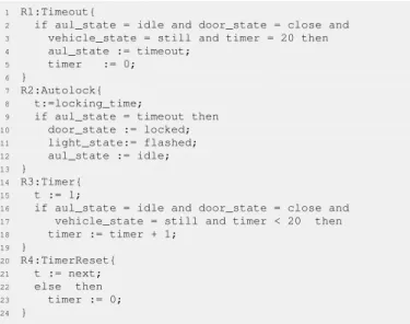
The AUTO LOCKOUT machine, as shown in Figure 8, models the behaviors of the Auto-Lockout use case. The Rule Timeout represents that when the vehicle stops and the doors are close, the feature will be activated upon the timeout expires (i.e., 20s in our case). The Rule Autolock represents that the system is to automatically lock the doors. The Rule Timer represents the timer measuring time intervals. Rule Idle keeps the machine alive and represents that the timer will be reset either when the doors are open or when the vehicle starts running.
1 R1:ReceiveCommand{
2 if cllock_state = idle and keyfob_cmd = lock then
3 cllock_state := lockdoor;
4 keyfob_cmd := NONE;
5 }
6 R2:Locking{
7 t:=locking_time;
8 if cllock_state = lockdoor then
9 door_state := locked; 10 light_state := flashed; 11 cllock_state := idle; 12 } 13 R3:Idle{ 14 t := next; 15 else then 16 skip; 17 }
Fig. 7. The eTASM main machine models the CL Lock use case.
1 R1:Timeout{
2 if aul_state = idle and door_state = close and
3 vehicle_state = still and timer = 20 then
4 aul_state := timeout;
5 timer := 0;
6 }
7 R2:Autolock{
8 t:=locking_time;
9 if aul_state = timeout then
10 door_state := locked; 11 light_state:= flashed; 12 aul_state := idle; 13 } 14 R3:Timer{ 15 t := 1;
16 if aul_state = idle and door_state = close and
17 vehicle_state = still and timer < 20 then
18 timer := timer + 1; 19 } 20 R4:TimerReset{ 21 t := next; 22 else then 23 timer := 0; 24 }
Fig. 8. The eTASM main machine models the Auto-Lockout use case.
The ANTI LOCKOUT machine, as shown in Figure 9, models the behaviors specified in the Anti-Lockout use case. The Rule HasKey represents that when the vehicle stops, the feature will be activated if the key is in ignition. The Rule Antilockrepresents that the system is to unlock the doors after activated. The Rule Idle keeps the machine alive and represents that the system is idle.
4) Property Annotation: Validation of non-functional re-quirements in this stage relies on the estimates of the pertain-ing non-functional properties of the proposed system. This step can be carried out in the following ways:
• The properties are determined based upon the non-functional requirements specified in the use cases.
• The properties are determined by using the experience or analysis of existing systems (in which estimates can be obtained by using existing well-known analysis meth-ods, e.g., Worst-Case Execution Time (WCET) analy-sis [18], [19] for time duration of rules).
We annotate the aforementioned eTASM models with time durations, as shown in Figures 7, 8, and 9. The annotation
1 R1:HasKey{
2 if anl_state = idle and ignition_state = haskey and
3 vehicle_state = still then
4 anl_state := antilock;
5 }
6 R2:Antilock{
7 t:=unlocking_time;
8 if anl_state = antilock then
9 door_state := close; 10 anl_state := idle; 11 } 12 R3:Idle{ 13 t := next; 14 else then 15 skip; 16 }
Fig. 9. The eTASM main machine models the Anti-Lockout use case.
terms locking time and unlocking time are either a specific value or a range of values.
C. Feature Requirements Formalization
Our approach proceeds with the formalization of feature requirements by using the eTASM Observer technique, which consists of four sub-steps as follows:
• Step 3.1: Listener Specification specifies the possible events sequence which represents the proposed system’s observable functional behaviors and/or non-functional properties required by the feature requirements, and the corresponding actions taken on observer variables when the sequence is caught by a Listener.
• Step 3.2: Observation Specification formalizes a predi-cate depending on the observer variables. If the predipredi-cate of the Observation holds, i.e., evaluates to be true, it implies that the property satisfaction of the feature is achieved, as it can be observed in the proposed system.
• Step 3.3: Events Filtering identifies the interesting
events and filters out the irrelevant events by specifying EventsFilter.
• Step 3.4: Traceability Creation links a specific
Ob-server to the textual requirements. The link is used for requirements traceability from the formalization to natu-ral language requirements in order to perform coverage checking.
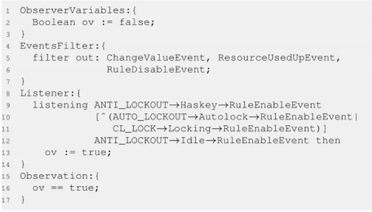
In the VLU system, there are four feature requirements, i.e., CL Lock, CL Unlock, Auto Lockout and Anti Lockout. The specification of an observer is illustrated by applying the proposed steps to the ANL feature requirement. To be specific, the ANL feature requirement states "The system shall anti-lock the doors if the key is in ignition and the vehicle has stopped", and the interesting events sequence consists of three parts. The first part "ANTI LOCKOUT→Haskey→RuleEnableEvent" denotes that the event is triggered when the Rule HasKey of the ANTI LOCKOUT machine is enabled, modeling the behavior that the key is in ignition. The second part "[ˆ(AUTO LOCKOUT→Autolock→RuleEnableEvent| CL LOCK→Locking→RuleEnableEvent)]*" represents an arbitrary number of events that are not triggered by the enabling of either the Rule Autolock of the AUTO LOCKOUT
machine or the Rule Locking of the CL LOCK machine. Both of these two rules model the behavior that the doors are locked. The last part "ANTI LOCKOUT->Idle->RuleEnableEvent" represents the event that is triggered when the Rule Idle of the ANTI LOCKOUT machine is enabled, which models the situation in which the key is removed. If the events sequence is detected, the Observation "ov == true" evaluates to be true, which indicates the situation in which after the key is in ignition, the doors are not locked before the key is removed, i.e., the ANL feature requirement is satisfied in the eTASM model.
1 ObserverVariables:{
2 Boolean ov := false;
3 }
4 EventsFilter:{
5 filter out: ChangeValueEvent, ResourceUsedUpEvent,
6 RuleDisableEvent; 7 } 8 Listener:{ 9 listening ANTI_LOCKOUT→Haskey→RuleEnableEvent 10 [ˆ(AUTO_LOCKOUT→Autolock→RuleEnableEvent| 11 CL_LOCK→Locking→RuleEnableEvent)] 12 ANTI_LOCKOUT→Idle→RuleEnableEvent then 13 ov := true; 14 } 15 Observation:{ 16 ov == true; 17 }
Fig. 10. The observer for the ANL feature requirement.
D. Feature Validation
Validation of the formalized requirements aims at increasing the confidence of the validity of selected features. In this work, we assume that there is a semantic equivalence relation between the RUCM use cases and eTASM models. This is built upon the fact that the eTASM models are derived, by following the proposed modeling steps as well as our thorough understanding of the VLU system. The validation goal is achieved by following several analysis steps, based on the use of the derived eTASM models which may help to pinpoint flaws that are not trivial to detect. Such validation steps in our approach are:
• Step 4.1: Logical Consistency Checking. The term
of logical consistency can be intuitively explained as "free of contradictions in the specifications". In our work, the logical consistency checking is performed on the executable eTASM models, by using our developed tool TASM TOOLSET. Furthermore, there are two kinds of inconsistency flaws to discover. One kind of flaws is that two rules in the same machine are enabled si-multaneously, which is usually caused by the fact that there exist unpredictable behaviors in the specification of the corresponding feature. The other is that different values are assigned to the same variable simultaneously by different machines, which is usually caused by the fact that there exist hidden undesirable feature interactions in the specifications of the corresponding features.
• Step 4.2: Coverage Checking. The coverage checking
corresponds to checking whether the feature requirements can be observed in the integrated feature specifications, which is an important activity of requirements complete-ness checking. To perform the coverage checking, all the feature requirements are translated into observers which monitor the execution of the features specifications, i.e., the derived eTASM models. If an Observation cannot hold, it indicates that although the features specifications satisfy their individual requirements in isolation, there are behavioral inconsistencies in the integrated feature specification.
• Step 4.3: Model Checking. The eTASM machines can
be easily translated into timed automata through the transformation rules defined in [15]. The transformation enables the use of the UPPAAL model checker to verify the various properties of the eTASM model. This type of checking aims at verifying whether the eTASM model is free of deadlock and whether an expected property specified in a feature requirement is satisfied by the eTASM model. It is necessary to stress that the essential difference between Model Checking and Coverage Check-ingis whether a property is exhaustively checked against a model or not. Although a sound property checking is desired, in some cases Model Checking will encounter state explosion problem, which limits its usefulness in practice.
We follow the aforementioned validation steps to check the validity of the selected features of the VLU system. First, we use the TASM TOOLSETto perform Logical Consistency
Checking on the formalized eTASM model. Two inconsis-tencies are detected, one of which is that the Rule Autolock of the AUTO LOCKOUT machine and the Rule Antilock of the ANTI LOCKOUT machine update the door state vari-able simultaneously with different values. An analysis of the inconsistency reveals: When the key is in ignition, the ANL feature will keep the doors unlocked. Meanwhile, if the autolock timeout expires, the AUL feature will try to lock the door. Since no rules are explicitly specified in the selected features to handle this situation, undesirable behaviors will occur. The other inconsistency is detected in a similar situation where the Rule Locking of the CL LOCK machine and the Rule Antilock of the ANTI LOCKOUT machine update the door state variable simultaneously with different values. In this work, we correct such inconsistencies by assigning a higher priority (as an extra condition of the corresponding rule) to the Rule Antilock, which guarantees that it will be executed at first when both of two rules are enabled at the same time. Note that there are some other methods that can be used to remove the discovered inconsistencies, which are however out of the scope of this paper.
After the removal of the inconsistencies, we proceed to Coverage Checking. The TASM TOOLSETis applied, and the result has shown that the observations of all eTASM observers are met. Therefore, the integrated features specifications
sat-isfies the feature requirements, from the Coverage Checking perspective.
On the note about Model Checking, we first translate the eTASM model into timed automata, and then check the deadlock property as well as the feature requirements via UPPAAL. The corresponding results are: 1) Deadlock free is satisfied and, 2) the CL Lock feature requirement is satisfied and, 3) the CL Unlock feature requirement is satisfied and, 4) the AUL feature requirement is satisfied and, 5) the ANL feature requirementis satisfied. As a result, the satisfaction of deadlock-free and feature requirements has been achieved.
In summary, our approach has found two behavioral incon-sistencies in the integrated features specifications. Although the VLU system is not complex, it is enough, as an illustrative example, to show how to perform feature-oriented require-ments validation by following our proposed approach.
V. RELATEDWORK
Kimbler et al. [20] introduce a user-oriented approach to feature interaction analysis. It aims first at creating use case models to describe different possible ways of using the system services, and then building service usage models which simulate the dynamic relations between services. This work is quite similar with our idea, however its focus is in the telecommunication domain. Moreover, we use the RUCM approach to facilitate the transformation from use case models to subsequent formalisms. Eriksson et al. [21] propose a software product line use case modeling approach i.e., PLUSS to modeling SPL. The difference between their work and ours is the purpose of using use cases. PLUSS aims to utilize use cases to capture variants of SPL, while our approach utilizes use cases to specify behavioral specifications of features. The white paper of EAST-ADL [16] mentions that use cases can be used to specify features but no more details were given. In this work, we have provided a set of steps to specify features and perform requirements validation.
Amyot et al. [10] propose an approach to detecting feature interactions of telecommunication systems, by using Use Case Maps (UCMs) for designing features, and LOTOS for the formal specification of features. Sampath et al. [22] present a formal specification and analysis method for automotive features in the early stages of software development process. This method starts with an empty specification, and then incrementally adds clauses to the specification until all the feature requirements are satisfied. Arora et al. [7] propose a method and algorithms for identifying and resolving feature interactions in the early stages of the software development life-cycle. The work uses State Machines to model the be-havior of independent features, context diagrams to integrate independent features, and Live Sequence Charts to capture the interactions of features.
VI. CONCLUSIONS ANDFUTUREWORK
In this paper, we have proposed a novel approach to feature-oriented requirements validation by using the RUCM approach and the eTASM language. Our approach 1) specifies the
behaviors and requirements of features in the RUCM use cases and, 2) transforms such RUCM use cases to the formal yet literate eTASM models and, 3) performs the requirements val-idation by using the TASM TOOLSETand the model checker UPPAAL. Our illustration application using a Vehicle Locking-Unlocking (VLU) system has shown that our approach can achieve the goal of feature-oriented requirements validation via Logical Consistency Checking, Coverage Checking, and Model Checking.
As inspired by Scandurra et al. [17] showing the promise of rule-based transformation from RUCM use cases to analysis models, we will in the future combine the proposed modeling approach with such rule/pattern-based algorithms, to achieve a fully automatic transformation between the RUCM use cases and eTASM models. We are also interested in integrating our approach and related tools for the development of correct-by-construction systems (e.g., developed by EAST-ADL lan-guage) in a seamless and cost efficient way. Another part of future work also includes a wider industrial validation of our approach, as well as the improvement of our current TASM TOOLSET.
REFERENCES
[1] K. C. Kang, S. G. Cohen, J. A. Hess, W. E. Novak, and A. S. Peterson, “Feature-oriented domain analysis (foda) feasibility study,” Tech. Rep., Nov 1990.
[2] J. Bosch, Design and Use of Software Architectures: Adopting and Evolving a Product-line Approach. New York, NY, USA: Addison-Wesley Professional, May 29, 2000.
[3] A. Classen, P. Heymans, and P.-Y. Schobbens, “What’s in a fea-ture: A requirements engineering perspective,” in Proceedings of FASE’08/ETAPS’08, 2008, pp. 16–30.
[4] D. Benavides, P. Trinidad, and A. Ruiz-Cort´es, “Automated reasoning on feature models,” in Proceedings of CAISE’05. Springer-Verlag, 2005, pp. 491–503.
[5] X. Peng, W. Zhao, Y. Xue, and Y. Wu, “Ontology-based feature modeling and application-oriented tailoring,” in Proceedings of ICSR’06, 2006, pp. 87–100.
[6] M. Mendonca, A. Wkasowski, and K. Czarnecki, “Sat-based analysis of feature models is easy,” in Proceedings of SPLC’09, 2009, pp. 231–240. [7] S. Arora, P. Sampath, and S. Ramesh, “Resolving uncertainty in auto-motive feature interactions,” in Proceedings of RE’12, Sep 2012, pp. 21–30.
[8] A. F. Layouni, K. J. Turner, and L. Logrippo, “Conflict detection in call control using firstorder logic model checking,” in Proceedings of ICFI’07, 2007.
[9] S. Apel and C. Kstner, “An overview of feature-oriented software development,” 2009.
[10] D. Amyot, L. Charfi, N. Gorse, T. Gray, L. Logrippo, J. Sincennes, B. Stepien, and T. Ware, “Feature description and feature interaction analysis with use case maps and lotos,” in Proceedings of FIW’00, 2000, pp. 274–289.
[11] M. Poppleton, “Towards feature-oriented specification and development with event-b,” in Proceedings of REFSQ’07, 2007, pp. 367–381. [12] T. Yue, L. C. Briand, and Y. Labiche, “A use case modeling approach to
facilitate the transition towards analysis models: Concepts and empirical evaluation,” in Proceedings of MODELS’09, 2009, pp. 484–498. [13] J. Zhou, Y. Lu, and K. Lundqvist, “A tasm-based requirements validation
approach for safety-critical embedded systems,” in Proceedings of Ada-Europe’14, June 2014.
[14] O. M. Group, “OMG Unified Modeling Language (OMG UML), Infras-tructure, V2.1.2,” Tech. Rep., Nov. 2007.
[15] M. Ouimet, “A formal framework for specification-based embedded real-time system engineering,” Ph.D. dissertation, Department of Aeronautics and Astronautics, MIT, 2008.
[16] H. Blom, H. L¨onn, F. Hagl, Y. Papadopoulos, M.-O. Reiser, C.-J. Sj¨ostedt, D.-J. Chen, and R. T. Kolagari, “EAST-ADL - An Architecture Description Language for Automotive Software-Intensive Systems,” The EAST-ADL 2 Consortium, Tech. Rep., 2012.
[17] P. Scandurra, A. Arnoldi, T. Yue, and M. Dolci, “Functional require-ments validation by transforming use case models into abstract state machines,” in Proceedings of SAC’12. NY, USA: ACM, 2012, pp. 1063–1068.
[18] R. Wilhelm, J. Engblom, A. Ermedahl, N. Holsti, S. Thesing, D. Whal-ley, G. Bernat, C. Ferdinand, R. Heckmann, T. Mitra, F. Mueller, I. Puaut, P. Puschner, J. Staschulat, and P. Stenstr¨om, “The worst-case execution-time problem—overview of methods and survey of tools,” ACM Transactions on Embedded Computing Systems (TECS), vol. 7,
no. 3, pp. 1–53, April 2008.
[19] Y. Lu, “Pragmatic Approaches for Timing Analysis of Real-Time Embedded Systems,” Ph.D. dissertation, M¨alardalen University, June 2012.
[20] K. Kimbler and D. S. birk, “Use case driven analysis of feature interactions,” in Feature Interactions in Telecommunications Systems, IOS, 1994, pp. 167–177.
[21] M. Eriksson, J. B¨orstler, and K. Borg, “The pluss approach: Domain modeling with features, use cases and use case realizations,” in Pro-ceedings of SPLC’05, 2005, pp. 33–44.
[22] P. Sampath, S. Arora, and S. Ramesh, “Evolving specifications formally,” in Proceedings of RE’11, Aug 2011, pp. 5–14.