Postadress: Besöksadress: Telefon:
Box 1026 Gjuterigatan 5 036-10 10 00 (vx) 551 11 Jönköping
A Study of Small Engine Tests
Eric Josefsson
Henrik Henningsson
Postadress: Besöksadress: Telefon: Box 1026 Gjuterigatan 5 036-10 10 00 (vx) 551 11 Jönköping
EXAM WORK 2015
SUBJECT
Mechanical Engineering
This exam work has been carried out at the School of Engineering in Jönköping in the subject area construction engineering. The work is a part of the two-year university diploma program, Master of Science with a major in Product Development, specialization product development and materials engineering The authors take full responsibility for opinions, conclusions and findings presented.
Examiner: Roland Stolt Supervisor: Joel Johansson Scope: 30 credits
2
Abstract
Today the environmental issues are a lot on the agenda and the environmental awareness are more and more common. New laws and restrictions on engines emissions are enforced and the demand on the engines gets higher and tougher. This leads to the engine testing playing a more crucial part than ever.
Engine tests are done using an engine dynamometer. The dynamometer loads the engine by, in many different ways, absorbing the power and torque generated by engine. The most important functions of a dyno are to convey the power from the engine to the dyno, to load the engine, to measure the power and torque generated by the engine and to remove the excess heat that is generated.
Husqvarna is a Swedish company that produces garden and forest cutting tools, their most famous products are their chainsaws.
Husqvarna does an extensive amount of engine testing, long time testing,
functional testing and field testing. Some functional tests, such as start-ability after use is done in a climate chamber where the humidity and temperature can be set. Today, loading a chainsaw in -25 °C is a problem due to the fact that the most used dynamometer at Husqvarna is a water brake that freezes in minus degrees. This master thesis will answer the question on how to, for small engine, simulate the load that occurs during normal use of the engine and how to develop a dynamometer suitable for Husqvarna’s needs?
The focus when developing the dynamometer will lie on solving the problem with minus degrees and having a good detachable coupling between the dyno and the chainsaw.
The result is a hydraulic oil dynamometer. A hydraulic pump is attached to the guide bar and chainsaw using a detachable key way coupling and bearings. By controlling restriction of the flow in the hydraulic system the load can be controlled and also ultimately the RPM of the chainsaw.
The hydraulic oil works fine in the minus degree as long as the right oil with the right viscosity range is used although a problem with the small chainsaws are that they are not reaching the full RPM in -25 °C. Mainly because of the backpressure created by the components in the system. This can be solved by minimizing the hydraulic systems total flow restriction.
However this problem doesn’t affect the testing methods as long as the chainsaw easily can be disconnected and freed from the dynamometer and then be run to full RPM which the coupling between the pump and chainsaw enables.
3
Keywords
Engine test, Dynamometers, Husqvarna, Chainsaw, Small engines, low moment of inertia, high RPM, Absorbers, Hydraulic Oil Dynamometer, Coupling, Torque, Power, Measurement, Vibration, climate chamber, -25 °C.
Acknowledgments
The work done has been very successful and rewarding on both an academic and professional level. The project has proven to be much more work than anticipated
there are many parameters and function that needs to be taken into account when designing a new dynamometer. Without help from people from almost every
department this work would never have been possible.
Many thanks to our supervisors Jan Leijon and Joakim Arvby for giving us this opportunity and for their support through this proj
We would also like to thank Uno Sjölander, Staffan Ek, Lennart Wadén, Christian Liliegård, Peter Gustavsson and the people at COOR.
4
Contents
1 Introduction ... 6
1.1 BACKGROUND ... 6
1.2 ENGINE TESTING AT HUSQVARNA ... 7
1.3 PURPOSE AND RESEARCH QUESTIONS ... 8
1.4 DELIMITATIONS ... 8
1.5 OUTLINE ... 8
2 Theoretical Background ... 9
2.1 INTRODUCTION TO ABSORBING DYNAMOMETERS ... 9
2.2 COUPLING ... 10
2.2.1 Chassis Mounted Dynamometer ... 11
2.2.2 Crankshaft Mounted Dynamometer ... 12
2.3 ENGINE AND DYNAMOMETER CONTROL MODES ... 13
2.3.1 Position/speed mode ... 14
2.3.2 Position/torque mode ... 15
2.4 VIBRATIONS ... 16
2.5 METHODS FOR MEASURING TORQUE ... 17
2.5.1 Trunnion-Mounted Dynamometers ... 17
2.5.2 In-Line Torque Measurement ... 18
2.6 DIFFERENT TYPES OF DYNAMOMETERS/BRAKES... 18
2.6.1 Electric Dynamometers ... 18
2.6.2 Air Brake ... 20
2.6.3 Hydraulic Brakes ... 21
2.6.4 Friction Brakes ... 24
2.6.5 Hybrid Systems ... 24
2.7 ANALYSIS OF ENGINE TEST AND REPORTS ... 25
2.8 SPECIFIC REQUIREMENTS ... 27
2.8.1 Low moment of inertia ... 27
2.8.2 Higher RPM ... 27
2.8.3 Down scale of components and measurements ... 27
2.9 NORMAL USAGE OF CHAINSAW ... 28
3 Method and Findings ... 28
3.1 HUSQVARNA’S ENGINE TESTS ... 28
3.1.1 Pros and cons ... 29
3.2 THE OBJECTIVE ... 30
3.3 PLANNING ... 31
3.4 REQUIREMENT SPECIFICATION... 32
3.4.1 Major Function Requirements ... 32
3.4.2 Major Handling Requirements ... 32
3.5 CONCEPT GENERATION AND SELECTION METHOD ... 33
3.5.1 PM-motor ... 34
3.5.2 Eddy Current Brake ... 35
3.5.3 Water Brake... 35
3.5.4 Hydraulic Oil Pump ... 35
3.5.5 Morphological Matrix ... 37
3.5.6 Weighing and Pugh-matrix... 38
4 Results, Further Development and Analysis ... 39
4.1 DESIGN OF COUPLING... 39
4.2 CALCULATIONS ... 40
4.2.1 Chainsaw: ... 40
4.2.2 Pump: ... 40
4.2.3 Strength at Nose sprocket:... 41
5
4.3.1 Test Procedures ... 43
4.3.2 Results: ... 43
4.4 SELECTION OF COMPONENTS FOR PROTOTYPE ... 45
4.5 TEST-RIG SETUP: ... 47
4.6 TEST OF FINAL PROTOTYPE ... 48
4.6.1 Test in room temperature ... 48
4.6.2 Test in climate chamber at -25 °C ... 50
5 Discussion and Conclusion ... 52
6 References ... 55
7 Figures: ... 56
7.1 APPENDIX 1 ... 57
6
1 Introduction
1.1 Background
An essential part of product development is to improve the product. The improvement can lie in the function of the product, the overall cost or
environmental impact etc. By using various methods of testing, the result can verify the performance of the new product and be compared to the older product or version.
In the engine manufacturing business the manufactures strives for a cheap, effective engine with low environmental pollution. The competition is hard, the price for gasoline is high and all the time new laws for engine emission are introduced.
In order to stay at the top in the engine business it is of high importance that the improvement of the engine is successful. Therefor testing of the engine is of equal importance. To find areas of which problems lies, to find areas where there is room for developments and to finally verify the improvement.
Engine tests are done by loading the engine to the degree that it simulates the work load or the working condition of the engine. During the test various outputs from the engine are monitored for output torque, power, emissions, build-up heat etc. Usually the test can consist of multiple different levels of workloads e.g. city driving or highway driving with a car.
Dynamometer is a device that measures the performance of the engine i.e. forces, power/horsepower, speed and torque generated.
A dyno (short for dynamometer) is either being driven or drives the machine that will be tested. A driven dynamometer absorbs for example the power from an engine and measures the forces. A driven dynamometer is called
“absorption-dynamometer”.
A dynamometer that drives the component is called a “driving-dynamometer”. The driving dynamometers can be used, for example, to measure the torque that required driving a pump.
This thesis will focus on the absorption-dynamometer commonly used in engine tests. There are many variants of absorptions-dyno and what separates them are the different ways they absorb forces.
7
1.2 Engine testing at Husqvarna
Husqvarna is a global manufacturer of forest-, garden- and construction-equipment. Handheld chainsaws is a major product within Husqvarna which started the production of chainsaws in 1959. The handheld chainsaws are aimed both towards private and professional sector. Husqvarna produces both electric and petrol driven chainsaws but the work described in this report is limited to petrol driven chainsaws. The size of the petrol driven chainsaws for private use range from 40.9 cm3 (1.5 kW) to 50,2 cm3 (2.4 kW) and the size range for the professional chainsaws is 43.1 cm3 (2.2 kW) to 118,8 cm3 (5.9 kW). The maximum torque and power lies in the rpm range of 8000 – 12000 rpm for the whole petrol driven chainsaw product range.
In order to ensure that these chainsaws fulfils the intended quality specifications and performs as expected Husqvarna has conducted a large set of test methods. A problem with almost all test methods is that there are a lot of variables that needs to be under control to make the results as consistent and reliable as possible. This is something that Husqvarna is looking into. As their products get more optimized the demand for more precise and accurate measurements are increasing.
The major test areas for the chainsaws are long term testing, functional testing and field testing. Within these test areas are a range of different test methods that are used to evaluate for example emissions, product life time and wear of different parts. The test area that this work has been conducted on is the functional testing that takes place in a climate chamber.
The equipment currently used consists of a climate chamber and an absorption-dyno that is either a water-brake that uses water to absorb energy or a trimmer-head that uses air resistance. These dynos is used depending on the conditions in the climate chamber, the water-brake is used in any temperature above 0 °C. If the temperature is sub-zero degrees only the trimmer-head can be used. The two types of brakes are used to simulate the force that is applied on the chainsaw when cutting through a tree log. The climate chamber has a temperature range between -25 °C and 40 °C. The issues with the current solutions, the water-brake and the trimmer-head, is that they are tedious to setup, the water-brake doesn’t work in sub-zero conditions and the trimmer-head solution could potentially be dangerous because of the fast rotating trimmer lines.
8
1.3 Purpose and Research Questions
The objective is to design a prototype of a new functional test setup for the handheld chainsaw that simulates the condition the chainsaw is subjected to in normal use.
The research question will be:
How to develop a dynamometer to simulate normal usage of small engines?
1.4 Delimitations
The secondary question will be:
How to develop a dynamometer suitable for Husqvarna’s engine tests?
The dynamometer that will be developed is limited to an absorber, shaft design or power transmission, measuring device, the rig, and if necessary a heat transfer unit.
The dynamometer must function through all possible environments that the climate chamber can provide (-25 to 40 °C).
Since there are few reports on dynamometers for small engines, this report will focus on engines between 40-120 cc.
1.5 Outline
This report covers the methods of testing small engines and how the methods and information can be applied to the project at Husqvarna.
The theoretical background will about different methods of applying loads to an engine, where to apply the load and which method that suits which situation. The method and findings will be about how these methods can be used at Husqvarna and the selection method.
After that follows the testing of the selected method and the final results. Lastly the final discussion and conclusion about this master thesis are presented.
9
2 Theoretical Background
2.1 Introduction to Absorbing Dynamometers
Dynamometers are used widely in many applications. The most common
application is in the car industry which uses dynamometer to measure the torque of the combustion engine.
In the machining (milling and drilling) process one of the most important variables is the cutting force that is generated by the cutting tool which can be measured with a dynamometer. [1]
The dynamometer is useful in biomechanical studies where the grip force of the human hand in various activities is of high importance. [2]
What they all have in common and the main purpose of the dynamometer is to translate energy from a source and measure the energy translated through the dynamometer. Through the measurements, the force generated by the source can be calculated and evaluated. In the case of a combustion engine, the force that needs to be measured is in the form of torque. [3]
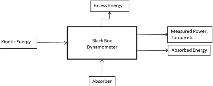
The black box (Figure 1: Black Box of an Absorbing Dynamometer) below shows the inputs and outputs of an absorbing dynamometer.
The kinetic energy is the torque from the engine or the force from the cutting tool and grip force. This energy is translated and absorbed by the “absorber”. The absorber could be in the form of springs, electric engine, hydraulic systems and many more.
All the energy entering the absorber cannot be absorbed, energy is “leaking” in the form of friction/heat generation. This can be viewed as a margin of error if not taken in consideration when measuring the absorbed energy. To avoid this the force can be measured using load sensors and the torque and power can then be calculated.
To get an additional understanding and overview of the dynamometer a function means tree has been done (see Figure 2 b elow).
10
Figure 2: Function means tree structure of an absorbing-dynamometer
2.2 Coupling
A crucial question that arises when developing a dynamometer for a product is where to attach the dynamometer to the product i.e. where should the coupling be. There are two extreme points on where to put the coupling.
Either it can be attached at the most outmost point where the product delivers its power or it can be attached to the most inner point of the products power. For example a cars most utmost point of power is the wheels and the most inner point of power is the crankshaft. These two different ways of mounting the
dynamometer will be called chassis mounted dyno and crankshaft mounted dyno. Where to put the coupling is not the only question that needs answering. How to transfer the power is another big question. There are several ways to connect the dyno and transfer the power, especially in chassis mounted dynamometer. The crankshaft mounted dyno almost always use a simple axis shaft power transfer since it is the most convenient solution, shaft out from engine and shaft in to dyno. With chassis mounted dynamometer the design of the power transfer is highly dependent on how the final power output of the product looks like. When designing and dimensioning the coupling, not only the strength of the coupling is important, vibrations can have a huge impact on the fatigue strength.
The natural frequency of the vibrations needs to be avoided.
To relive a shaft coupling from the vibrations a part of the shaft can be made of flexible material that can dampen the vibration that would otherwise propagate. In cases where the combustion engine suffers the risk of failure a weaker part can be introduced to the coupling, in that way, if the engine fails and large loads propagate to the dynamometer the coupling/shaft will break before and spare the, often more expensive, dynamometer.
11 2.2.1 Chassis Mounted Dynamometer
The chassis mounted dyno is used when the performance of the product as a whole is of importance. Any dynamometer that is mounted close to the final power output can be called chassis mounted dynamometer. A chainsaw final power output is on the chain of the chain saw. To understand and measure the cutting force, power torque etc. a chassis mounted dynamometer is needed since there can be a lot of friction and other power “leakage” between the crank shaft and the chain that needs to be taken into account.
Cars have a lot of transmissions and couplings from the crankshaft to the output of the wheels, therefore it can be very important to not only measure the power of the engine, but the power of the car itself. The chassis mounted dynamometers for cars are mounted beneath the car and the coupling between the car and the dyno is located on the driven wheels of the car. The dyno coupling is one or two rollers that the frictions of the wheels drive (see Figure 3). The absorber then loads the engine by absorbing the roller torque.
Figure 3: Test cell with chassis mounted dynamometer [4]
The car-test area that contains chassis mounted dynamometer can be called a test cell. In the test cell various tests can be made to conclude for example the wheel power output, emissions or heat generation.
12 2.2.2 Crankshaft Mounted Dynamometer
The chassis mounted dynamometer isn’t always the correct choice although it takes all parameters and components in consideration. In many cases it is interesting to focus on the engine alone especially in engine development or engine improvement. In that case the crankshaft mounted dynamometer should be used to isolate the problems and easier conclude areas that need improvement. In such tests the accuracy of the measurements from the dyno are of high
importance compared to chassis mounted where there are a lot of varying
parameters that possibly can eliminate the accuracy of the measuring values. Figure
2 below show a fairly standard dynamometer (electric generator or eddy current
brake) coupled directly upon the crank shaft of the combustion engine.
Since the dynamometer is coupled directly on the engine there could be problems with vibrations. The engine vibrates with high forces witch each piston stroke and the forces and vibrations are then directly translated to the shaft going to the dynamometer. The connecting shaft is the most vulnerable part since it has the lowest strength yet it is subjected to the highest stresses. This is so that shaft will break before other more expensive components. In order to solve this problem the engine and dynamometer can be mounted on dampeners, in that way they can vibrate together with almost the same amplitude and frequency relieving the connecting shaft. [3]
13
2.3 Engine and Dynamometer control modes
When evaluating an engine attached to a dynamometer, a test-program is utilized. The test program consist of desired values of torque and speed that can be
controlled by manipulating the engines power output and the torque absorption of the dynamometer [6]. According to A.J. Martyr et al. [3] there are three ways to control the engine power output and four ways to control the torque absorption of the dynamometer.
Engine controls:
Constant throttle opening (position mode) Constant speed (speed mode)
Constant torque (torque mode) Dynamometer controls:
Constant control setting (position mode) Constant speed (speed mode)
Constant torque (torque mode)
Particular torque-speed characteristics (power law mode)
These controls can be combined in several ways to form the test-program. (The test programs are named after engine mode/dynamometer mode.)
The most common test-programs are position/speed and position/torque which basically means constant speed and constant torque.
14 2.3.1 Position/speed mode
In this mode a constant throttle opening is set manually on the engine, the dynamometer then adjusts the amount of torque absorbed to maintain a desired constant speed.
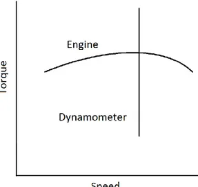
Figure 5 shows the position/speed mode, the dynamometer holds constant speed
with the varying torque output from the engine.
In order to have a smooth constant speed the RPM feedback needs to be frequent and fast and in addition, the torque absorption control needs to be equally
frequent and have sufficient resolution and response time.
For example if the air-fuel mixture suddenly reaches optimal condition, the RPM will increase, in order to counteract the increase in RPM the torque absorption needs to adjust accordingly.
The position/speed mode is used for instance in test where it is desired to maintain the speed at which the highest torque or power lies. For example Husqvarna uses a water brake to absorb torque to reach the desired speed where the highest torque is present. At the highest torque lies also the most optimal cutting speed which is where the chainsaws are usually used (at least by
professionals). By maintaining this constant speed for 20 minutes the work of cutting a tree in 20 min is simulated and the performance of the chainsaw can then be examined.
15 2.3.2 Position/torque mode
Position/torque almost works in the same way. The throttle opening is set to a constant value but, as Figure 6 shows, instead of regulating the amount of torque absorbed to maintain a constant speed, the position/torque mode sets the torque absorber in the dynamometer to a constant value and lets the RPM of the engine vary with the varying torque output of the engine.
Position/torque mode can be used to examine how the much the RPM varies with constant load and if the engine can find the best air-fuel mixture. The test-mode can also be used when the torque is of importance, for instance to simulate a car ascending a hill with constant incline. [3]
In order to avoid stalling of the engine there need to be caution not to load the engine beyond its capacity.
Stalling of the engine can not only ruin the engine but also the dynamometer, especially when high moment of inertia is present. [3]
16
2.4 Vibrations
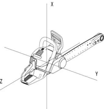
The main source of vibration within engine testing is the engine itself, the engine may be regarded as having six degrees of freedom through its centre of gravity. The vibrations that can appear are linear vibrations along each axis and rotation about each axis but in practice only three of these are usually of importance. These three are vertical oscillations on the X axis, rotation about the Y axis and rotation about the Z axis, see figure 7 below. [3]
Figure 7: Vibrational Axis
Even though the rotating masses of the engine are carefully balanced periodic forces are hard to avoid due to the interchanging masses of the crank, connecting rod and piston assembly. Another type of vibration comes from torque variations which are developed by each combustion stroke. These torsional oscillations will not only create a rotation about the Y axis but also create torsional stress on the shaft that connects the engine to the dynamometer. The engine and dynamometer can be regarded as two rotating masses which are connected to each other
through a flexible shaft. As the torque rises during the combustion stroke the engine tends to twist the shaft and the more inertia the dynamometer has the more twisting angle. [3]
A simple analysis of vibrations in the vertical direction will in most cases give a satisfactory result. If the engine is tall with mounting points at a low level and if cyclic variations in torque may create rolling of the engine then a complete
computer analysis of the different vibration modes and the shaft coupling may be advisable. [3]
17
The problems that might occur if the design of the coupling shaft system and engine mounting points is faulty are listed below.
Torsional oscillations
Vibration of engine or dynamometer Whirling of coupling shaft
Damage to engine or dynamometer bearings Excessive wear of shaft-line components Catastrophic failure of coupling shafts Engine starting problems
The general aim is to avoid coupled vibrations such as pitching forces due to unbalanced forces in the vertical direction or rolling moments due to the torque variations exerted by the engine. Compared to the frequency of vertical
oscillations these can create resonances at much higher frequencies which can lead to large consequences to the coupling shaft. [3]
2.5 Methods for Measuring Torque
2.5.1 Trunnion-Mounted DynamometersA Trunnion-Mounted dynamometer is a power-absorbing element mounted in a “cradle” supported by trunnion bearings. As the power is absorbed the
dynamometer will tend to rotate the cradle, the force required to prevent rotation is measured at a known radius, tangential to the machine axis, by some sort of transducer. The choice of trunnion bearing affect the calibration accuracy, which can be a combination of a ball-bearing and a roller-bearing or of hydrostatic type, where the latter usually gives higher accuracy but is more complex and expensive. An alternative to bearings is the Schenck dynamometer design where the bearings are replaced by two radial flexures, this design eliminates possible friction and wear but introduces a torsional stiffness and comprises the true centre of rotation because of the reduced ability to withstand axial loads. [3]
The earlier designs of this type of torque measurement, predating mid-1970s, used a physical balancing system with dead weights and a spring that would balance against the applied torque. To get an accurate measurement with this system it is necessary to adjust it so that the force measured is tangential to the axis. This is because it is not a stiff setup and it relies on gravity. [3]
18 2.5.2 In-Line Torque Measurement
This method measures torque in-line with the shaft connecting the absorber to the test engine. There are basically two types of systems using this method, one is the torque shaft and the other is the torque flange. The in-line torque shafts and torque flanges are both mounted on the axis between the absorber and the engine that is tested, the torque flange is bolted directly to the input flange of the
absorber and the torque shaft is mounted in the drive shaft. A torque shaft is basically a torque shaft fitted with strain gauges and assembled with a double-fanged, pedestal bearing and the torque flange is in the form of a disk. This method will not give as accurate torque measurements, under steady-state testing, as the trunnion-mounted dynamometer but has the advantage that no torque corrections are necessary under transient conditions. [3]
2.6 Different Types of Dynamometers/Brakes
2.6.1 Electric DynamometersThese types of system are probably the most common dynamometers within the automotive industry test facilities. They are capable of absorbing and motoring in both rotational directions. Complex control systems make them capable of dynamic simulations of real-life powertrain functions such as gear-shifting, wheel-slip and logged real life drive routes. A favourable property with these systems is that because they act as a generator when absorbing power from the engine under test these systems will generate electricity. This electricity may be utilized to power other test cells within the facility or to be returned to the power grid. [3] There are three main types of absorbers within this branch of dynamometers all with the same main functions but with different properties:
Asynchronous Motor (AC)
The AC motor has a lower inertia compared to an equally rated Direct Current motor it also has a higher speed range. These systems require a large and heavy drive cabinet that has to be taken into account when designing the test cell. [3]
Direct Current Motor (DC)
This is a mature technology that is often used in chassis dynamometers. These motors are robust and easy to control. The disadvantages are the limited maximum speed and the high inertia. As described in 2.4 a high inertia can present problems with torsional vibrations within the shaft system and limited rates of speed changes. The DC motors also require a more regular maintenance since it uses brushes. [3]
19
Permanent Magnet Motor (PM)
The PM motor has the lowest inertia of the three which makes it the most dynamic absorbing and motoring dynamometer with rapid speed changes and capabilities of high speeds. They are small in size but as the AC motor they require large and heavy drive cabinets. This is also the most expensive system. [3]
Eddy-Current
The eddy-current brake consists basically out of three assemblies, rotor and shaft assembly, casing assembly and baseplate assembly. Two important features in the casing assembly are the coils and the loss plates. The loss plates are cooled by water and are located with fine clearance in relation to the rotor. It is between the rotor and loss plates that the braking torque is developed. The casing is mounted on the baseplate by the principles of trunnion bearings, described in 2.5.1 [3] [7]
Eddy currents are electric currents that are induced in a conductor by a magnetic field as the conductor moves though the magnetic field which in the case of an eddy-current dynamometer is generated by magnetizing coils. As the rotor, in most common types a toothed rotor of high
magnetic permeability steel, cuts the magnetic field it will cause disruption of the magnetic flux in the loss plates which generates circulating eddy currents. The eddy currents in turn generates a magnetic field that opposes the magnetic field generated by the coils this effect will counteract the rotation of the shaft. The absorbed energy is transferred to the cooling water, which circulates through passages in the loss plates, in the form of heat as a result of electrical resistive losses. The magnetic field generated by the coils is controlled by adjusting the amount of current flowing through the coils. The input current to the coils is directly proportional to the absorbed power. [3] [7]
There are two types of eddy-current dynamometers, dry gap and wet gap. The dry gap type has air circulating in the gap between the rotor and loss plate and the wet gap uses water instead of air. The main difference
between these two types is that the wet gap has a higher moment of inertia, and is not as widely used in engine testing as the dry gap. There are two common forms of dry gap dynamometers, one with a single or several toothed disk rotors and another with a drum rotor. The dry gap
dynamometer with disk rotors has a lower inertia but is more sensitive to cooling water conditions than the drum rotor type. [3] [7]
20
In general the advantage of eddy-current dynamometers is that they are mechanically simple, have low inertia and are well adapted to computer control systems. The downsides are on the other hand that they are sensitive to poor cooling and thermal cycling which in turn require a well maintained and controlled water cooling system. [3]
Magnetic Powder Brake
The magnetic powder brake is a variant of the eddy-current brake but in the gap between the stator and the rotor were an eddy-current brake has air the magnetic powder brake also has a fine magnetic powder. The main advantage of the magnetic powder brake is that it can absorb full-rated torque all the way down to zero RPM. A limiting factor with this concept is the difficulty in dissipating the generated heat, this limits the maximum power and maximum speed of the brake, typically a maximum of 50 kW and 2000 RPM. [3]
Hysteresis Brake
Two of the most efficient technologies in the smaller power range, max 150 kW, are the hysteresis brake and the disk-type eddy current brake. The design of the hysteresis brake allows for full torque to be generated at full speed down to zero speed. Compared to the disk-type eddy-current design it has a rotor and a stator with coils but the rotor is formed as a cup and the stator encapsulates the walls of the cup instead of the stator on both sides of a disk. [7]
2.6.2 Air Brake
This type of brake are not very common, they are mostly used in field testing of helicopter engines where noise is not an issue and accurate torque measurements over a wide speed range is not required. [3]
The brake consists of adjustable paddles attached to the input shaft. Because of limitations to adjustment and measurement on the fly torque has to be
predetermined by calibration using a DC or AC dynamometer. Also the
repeatability is limited as the brake is susceptible to atmospheric changes such as air temperature, air pressure and humidity. The air brake serves best as a pass or fail type of brake because the only measuring parameter is the RPM. [7]
21 2.6.3 Hydraulic Brakes
Water Brakes
These types of absorbers brake the power source through friction and high turbulent shear of water flowing through a water sealed casing. The
turbulence is caused by vanes set at an angle both in the rotor, which is driven by the power source through a shaft, and in the stator, that is the casing. As the power source drives the rotor centrifugal force creates an intensive toroidal circulation, this effect transfers momentum from the rotor to the stator and, as the stator is fixed, creates a resistance to rotation of the shaft connected to the power source. [3]
Constant-Fill
This type of water brake has the casing filled with water at a set water flow. The variation of torque absorbed is managed by adjusting pairs of thin sluice plates, exposing or concealing vanes and thereby controlling the development of toroidal vortices. [3] [7]
Variable-Fill
A water brake adjusting torque by variable-fill is varying the amount of water circulating the casing which in turn absorbs different amount of torque. The water flow is controlled by a valve usually located at the water outlet. The advantage with this type of brake, compared to constant-fill, is that the torque can be adjusted more rapidly. [3]
Variable-Fill Bolt-On
The bolt-on variable-fill water brake has the same working principles as the variable-fill water brake, but with simplified design and lower mass to be able to be mounted directly to the engine clutch housing or to truck chassis. This simplified design however does not have the same level of speed holding or torque measurement compared to other water brake designs. The water fill level and water flow are usually controlled by an inlet control valve associated with a throttled outlet. [3]
Disk-Type
The disk dynamometer absorbs power by intensive shearing of water by one or more disks with fairly small clearance to flat stator plates. The torque is controlled in the same way as the variable-fill type, described in
2.7.6.1.2. This type of dynamometer is suitable for braking gas turbines
22
Hydrostatic Brake
This setup usually consists of a fixed displacement and a variable
displacement pump/motor. The fixed displacement pump/motor acts as the absorber, the torque applied to the Pump/motor results in a high pressure hydraulic pressure. The variable displacement pump/motor will add the ability to drive the fixed displacement pump/motor which in turn can provide torque to the engine or drive line system under evaluation. Also unlike most non-electrical brakes the hydrostatic brake is capable of applying full torque down to zero speed. These features are shared with most electric AC and DC dynamometers which is one reason why hydrostatic dynamometers are not very widely used today. [3]
Hydrostatic Brake: Torque and Power Measurement/calculation
In most hydrostatic dynamometers an engine drives a pump which in turn drives hydraulic oil, in a closed system, to a certain flow depending of the RPM and piston size of the pump. A load can then be applied in form of adjustable restrictor that creates pressure in front of the restrictor.
Following equations and calculations shows how the torque and power can be measured and calculated in a hydrostatic brake:
Power equals force multiplied by speed,
𝑃 = 𝐹 × 𝑣 𝑃 = 𝑃𝑜𝑤𝑒𝑟 (𝑊)
𝐹 = 𝐹𝑜𝑟𝑐𝑒 (𝑁) 𝑣 = 𝑆𝑝𝑒𝑒𝑑 (𝑚/𝑠)
The engine creates a rotational power from its crankshaft conveyed to the pump. The rotational power and torque can be calculated by:
𝑃 = 𝑀 𝑛2𝜋60 𝑀 = 𝑡𝑜𝑟𝑞𝑢𝑒
𝑛 = 𝑅𝑜𝑡𝑎𝑡𝑖𝑜𝑛𝑠 𝑝𝑒𝑟 𝑚𝑖𝑛𝑢𝑡𝑒
𝑀 = 𝐹 × 𝑟 𝑟 = 𝑟𝑎𝑑𝑖𝑢𝑠
The pump the converts the rotational power to hydraulic power with a constant flow Q [m3/s] depending on the size of the piston displacement and RPM. Due to the restrictor in the hydraulic system a certain pressure ∆p [N/m2] will be created in front of the restrictor. From the flow and pressure the hydraulic power can be calculated.
23
The power calculation is derived by: The pistons speed v: 𝑣 =𝑄
𝐴 𝑄 = 𝐹𝑙𝑜𝑤 (
𝑚2 𝑠 )
The piston force F: 𝐹 = 𝑝 × 𝐴 𝑝 = 𝑃𝑟𝑒𝑠𝑠𝑢𝑟𝑒 (𝑁
𝑚2)
𝐴 = 𝐴𝑟𝑒𝑎 (𝑚2)
The hydraulic power P can then be calculated: 𝑃 =𝑄𝑝𝐴𝐴 ; 𝑦𝑖𝑒𝑙𝑑𝑠→ 𝑃 = 𝑄 × 𝑝 [8]
𝑃 = [𝑚𝑠3] × [𝑚𝑁2] 𝑦𝑖𝑒𝑙𝑑𝑠→ [𝑁𝑚𝑠 ] = 𝑃𝑜𝑤𝑒𝑟 (𝑊𝑎𝑡𝑡)
The hydraulic torque generated by the pump (with a displacement D [m3/rev] and ∆p [N/m2]) can be calculated with:
𝑀 = ∆p 𝐷 2𝜋 𝐷 = 𝐷𝑖𝑠𝑝𝑙𝑎𝑐𝑒𝑚𝑒𝑛𝑡 (𝑚 3/𝑟𝑒𝑣) 𝑀 = [𝑁 𝑚2] × [ 𝑚3 1 𝑅𝑒𝑣] ÷ [ 1 2𝜋] 𝑦𝑖𝑒𝑙𝑑𝑠 → [𝑁𝑚] [8]
After the restrictor in the hydraulic system the pressure drops while the flow is still constant. The overflow a power that is generated when the pressure drops is converted to heat power.
The heat power is calculated by following equation: 𝑃𝑣 = 𝜌𝑐∆𝑇∆𝑡𝑉 𝜌 = 𝑑𝑒𝑛𝑠𝑖𝑡𝑦 [𝑚𝑘𝑔3] 𝑐 = 𝑠𝑝𝑒𝑐𝑖𝑓𝑖𝑐 ℎ𝑒𝑎𝑡𝑐𝑎𝑝𝑎𝑐𝑖𝑡𝑦 [ 𝐽 𝑘𝑔𝐾] ∆𝑇 = 𝑇𝑒𝑚𝑝𝑒𝑟𝑎𝑡𝑢𝑟𝑒 𝑑𝑖𝑓𝑓𝑒𝑟𝑒𝑛𝑐𝑒 [°𝐶] 𝑉 = 𝑣𝑜𝑙𝑢𝑚𝑒[𝑚3] ∆𝑡 = 𝑇𝑖𝑚𝑒 𝑑𝑖𝑓𝑓𝑒𝑟𝑒𝑛𝑐𝑒 [𝑠] [8] The oil-hydraulic dynamometer is favorable due to its low cost, simple design and its environmental robustness. Since the torque and power can be calculated from the pressure and flow of the hydraulic oil there is no need to have trunnion/torque arm. However, there are many power losses due to mechanical - pump efficiency, volumetric pump efficiency and friction losses in the walls and turns of the piping. To get an accurate result these losses need to be taken in to account.
24 2.6.4 Friction Brakes
Prony Brake
This type of brake is considered to be one of the earliest dynamometers, dating back to the early 19th century. It uses a flywheel that is driven by the engine and wooden shoes that act as brake pads on the flywheel. The brake pads will create a reaction force on the frame and is measured by the use of deadweights or some sort of spring scale.
Rope Brake
This type of brake dates back to the mid-19th century and is a successor from the prony brake. The working principle that creates friction consists of a rope wound about a flywheel which works as a brake drum. One end of the rope is attached to a source that creates a force e.g. a weight. As tension is increased in the rope more friction is crated between the rope and the flywheel which in turn creates a responsive force that is measured at the other end of the rope. [7]
Multidisc Friction Brake
These brakes have a low RPM range and are for this reason used in low speed applications, such as large off-road vehicle transmissions. This brake is a successor from the rope brake but uses water-cooled multidisc to create friction. The main advantage is that this brake can develop full torque down to zero speed. [3]
2.6.5 Hybrid Systems
Hybrid systems can be a more cost effective alternative if there is a need to motor the engine that is to be tested. Because the required motoring torque rarely
exceeds 30 % of the engine output torque one might consider motoring the engine with a smaller AC or DC motor and using a less expensive type of brake for absorption. The control system on the other hand will be a more complex problem and might make some combinations less cost effective. These solutions are most common when the torque or speed of prime mover cannot be covered by a standard dynamometer. [3]
25
2.7 Analysis of Engine Test and Reports
In a report called “Performance and emissions testing of a small two stroke engine using midlevel glycol blend” by Ananth Padmanabha Rao Vemuri [9] the study is to test the effectiveness of an aftermarket spark plug from E3 Spark Plug when using a mid-level glycol blend gasoline.
The machine used for the sparkplug testing is a Yard Machine 3100m string trimmer and the test procedure is described by the author goes as follow: “The testing comprises running the engine at different load points and throttle positions to evaluate the cylinder head temperature, exhaust temperature and engine speed”. What is interesting with this report is how the load is applied to the engine. The different load points are applied by adjusting the length of the strings in the trimmer head until the desired RPM is reached. In this report the main goal with the dynamometer was to load the engine in order to evaluate the cylinder head temperature, exhaust temperature and engine speed. This way of engine testing’s, i.e. loading the engine to build up heat, are also used by Husqvarna when testing chainsaws in the climate chamber and Husqvarna also uses the trimmer head string for absorption. The main reason why the string absorption is used in
Husqvarna is because the sub-zero temperature doesn't affect it and unfortunately the main reasons it needs to be replaced is because of the long setup time, bad load accuracy and the safety hazard.
The extensive research on different reports and journals shows that electric generator DC or AC dynamometers are used as standards, while the eddy-current is one of the most common absorbers in dynamometers. Both are especially good when the measurements of torque or emissions are important, regardless of engine size or engine type. The assumption that AC or DC dynos are used the most will be strengthened in the following text.
In Journal [11] an experiment is conducted to analyse the emission rate of ammonia from light-duty vehicles. The vehicles analysed are standard passenger car and light-duty trucks from large car companies and the dynamometer used is described as a standard, chassis, single-roll electric dynamometer.
In report regarding evaluation of heavy-duty vehicle diesel engine efficiency [12] it can be read in the experimental setup section that two DC chassis dynamometer are used. One DC dyno for medium-duty engines up to 400 HP and 2900 RPM and one DC dyno for heavy-duty engines up to 800 HP and 2500 RPM. In addition the engine research centre had access to an AC crankshaft dynamometer for engines up to 280 HP but this dyno was not used in the experiment.
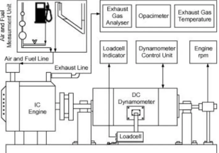
In Journal [13] a small diesel engines performance and emissions are examined. The diesel engine was a single cylinder, direct injection and four-stroke engine with a max effect of 4.7 HP. The experimental setup consisted of (see Figure 8) a DC crankshaft dynamometer that provided engine torque and speed parameters, a
26
fuel flow meter that measured fuel consumption and an exhaust gas analysis system that obtained emission parameters.
Figure 8: Experimental set up
The emissions where measured at the constant rated torque speed of 2600 RPM and four different engine loads, 13.1 Nm, 9.8 Nm, 6.6 Nm, and 3.3 Nm.
These three articles where picked and described because they all show several trends that most articles and reports about dynamometers have in common:
All three are written after the 2000s which is important to notice since technology always advances fast
Two of them is about emission ratings which is high on the agenda today They all use an electrical generator AC or DC as dynamometer regardless
of engine size, power and mounting
The conclusion that can be made is that the electrical dynamometers are probably used the most today and, in different variant, can load different sized engines with high precision. There needs to be a larger investigation with more numerous articles and reports in order to ultimately prove this assumption, but in this report it is enough to just see the trend in the literature.
When the precision of the applied load and the precision of the torque
measurement are of low importance and when simplicity, effectivity and low costs are more desired qualities, the electrical dyno falls short. In such cases the design of the dynamometer is more dependable on the current situation.
27
2.8 Specific Requirements
There are some certain design parameters that when designing a dynamometer for small engines needs to be analysed in order to design a successful dynamometer. These are in relation to automotive industries:
Low moment of inertia Higher RPM
Smaller sized components
Down scale in size, strength and in precision of measurement
2.8.1 Low moment of inertia
Moment of inertia is a term that that determines the amount of torque that is needed to accelerate a body to rotate around an axis, it also determines the amount of torque that is needed to decelerate the body.
In order to save the shaft/ transmission and the engine in case of engine failure the moment of inertia of the absorber is required to be proportional to the moment of inertia of the engine.
If the engine breaks down the absorber won’t have enough stored torque to twist the shaft or damage the engine if its moment of inertia is low enough.
2.8.2 Higher RPM
Small engines work at a higher rate of rotations per minute than larger engines. This is due to the fact that they have smaller displacement, 40-120 cc and therefore smaller piston. Since small displacement engines generate low torque they need to rev higher in order to create more power provided that the torque is peaking at a high RPM. The smaller piston can rev at a faster speed than larger pistons due to its low weight. So to get the most amount of power out of a small displacement engine is comes natural to increase the RPM.
The design of internal parts such as intake port etc. contributes to how the shape of the torque curve will look likes and where, on the RPM scale, the highest amount of torque will be. Small engines are usually designed to reach their highest torque output when the RPM is high.
2.8.3 Down scale of components and measurements
A normal passenger car has a torque of between 200 - 300 Nm, the dynamometer that measures the torque then needs an accuracy of about 1 Nm. When simply down scaling the engine and dynamometer the engine could have about 5 – 20 Nm and the accuracy needs to be a lot better, about 0.05 Nm. This can become a difficulty when choosing components for the absorber since smaller sized
components that has the same properties as large sized components but scaled downed are more expensive and rarer.
28
2.9 Normal Usage of Chainsaw
When a professional uses the chainsaw to cut logs he revs up to max rpm and then lets the chainsaws own weight push against the log. The rpm, due to the resistance of the log, will then decrease to, hopefully, the optimal cutting speed which is between 8.000 to 12.000 rpm depending on the size of the chainsaw.
3 Method and Findings
3.1 Husqvarna’s Engine Tests
In the introduction 1.2 three areas of engine testing performed at Husqvarna are mentioned, functional testing, long term testing and field testing.
In field testing the chainsaws are tested in their field of use either by Husqvarna employees or by professional chainsaw users that received a Husqvarna chainsaw for free provided that they will report problems with performance etc.
The environment of use can for example be cutting huge trees in Canada, testing their function in the extreme cold in northern Russia or testing in the moist environment of Brazil.
The long term testing is instead done in testing boxes in Husqvarna’s facilities. Here the tests occur during a long time under controlled circumstances. Test subjects are, among others, emissions measurements, full rev, variable rev (simulating normal use or aggressive use), torque and power dyno run etc. The control of modes mentioned in 2.3 of the testing is varying between
position/speed mode and position/torque mode. Water brakes are used in these test boxes and Eddy current brakes are used in the engine performance test rigs due to its low moment of inertia and good controllability.
The functional tests are mostly done in the climate chamber where environmental temperatures can be set. Here the test are done under less controlled circumstance regarding the RPM and torque measurement but there are a closer human control instead by hearing and feeling the performance of the chainsaw. Tests that are done here are closely related to specified component´s wear, heat generation, the start ability and more.
In the climate chamber the loading are done using a water brake attached to the guide bar of the chainsaw or using a trimmer head that also is attached directly on the guide bar tip. Both these absorber are controlled by setting full throttle, measure the RPM and try to reach as close as possible a desired RPM. The variation of the engine torque output will change the RPM but the water brake will compensate for this by changing the supply of water, the trimmer head on the other hand cannot compensate for this torque variation.
The water brake has a coupling between the nose sprocket and the rotor of the water brake this coupling uses clamp connection on the nose sprocket and an axis through the clamps that is hold by two bearings. The rotor is the enclosed and sealed by the stator and the whole water brakes sits on an approximately half length shortened guide bar.
The load can be controlled to an extent by controlling the water flow on the input on the brake and there are two size variants of the rotor and stator that can be
29
Trimmer head brake:
Pros:
Works in subzero temperatures Good range in the torque spectra Cons:
Bad torque controllability Dangerous to use
Top RPM not available used depending on the size of the chainsaw that will be tested. Smaller rotor and stator are for smaller chainsaws in order for them to be able to drive the rotor to the desired RPM.
The trimmer head brake is a simple air-fan brake, it is mounted in the same manner as the water brake but instead of the water rotor there is a trimmer head with trimmer cords. These trimmer cords act as a fan brake, when cutting through the air in high speeds of about 7000-9000 RPM the friction of the air on the trimmer cords loads the chainsaw engine.
The adjustment of the loading torque is set by cutting the length of the trimmer cords until desired RPM is reached, this way of adjusting the torque of the absorber is time consuming and inaccurate.
Figure 9: Trimmer head (not the same as on the brake)
3.1.1 Pros and cons
Water brake:
Pros:
Simple design
Ok/good torque controllability Portable
Cons:
Quite long setup time
Bad range in the torque spectra (two versions) Alters the weight distribution and handling Not possible in subzero temperatures
30
3.2 The objective
The objective is to define how dynamometers can be developed for use in small engines (under normal use). This is done by analyzing and developing such a system for chainsaws at Husqvarna. Husqvarna desires to be able to load chainsaws in the climate chamber at sub-zero temperatures and the task is to design this test rig.
The new design will not replace the water brake, it will still be used as a portable absorber as its only real big flaw is that it doesn’t work in sub-zero temperatures. It is important to see what the water brake lacks in order to create an absorber that not only works below zero degrees but also has the potential to performance better in other areas. The work will result in a physical fully functional prototype that will be tested to verify its functions and performance.
Project Objective
Design Organization: Husqvarna AB, Huskvarna Sweden Date: 2015-01-12 Proposed Product Name: Chainsaw Brake Rig
Project Name of Project: Mechanical Design of Brake rig
Objective: Develop a brake setup suited for chainsaws Key Questions:
How to, for small engines, simulate the load that occurs during normal use of the engine.
Deliverables: CAD solid model & 2D drawings
Functional prototype
Decisions Needed: Decision 1: Type of brake
Decision 2: Transmission/coupling Personnel Needed:
Title: Student Amount of work: 30 HP Title: Student Amount of work: 30 HP
Time estimate: Total hours: 800*2 h Elapsed time: 20
week
Sequence:
Start Date: 2015-01-12 Finnish Date: 2015-06-01 Cost: Capital Equipment
Team member:
Eric Josefsson Prepared by:
Team member:
Henrik
Henningsson Checked by:
31
Reference:
The Mechanical Design Process Professor David G. Ullman 2008 [14]
3.3 Planning
By following David G. Ullmans product development process these four steps were conducted. [13]
In order to finish the project within the time base established by Jönköping’s School of Engineering a Gant-scheme was created.
To obtain a detailed and extensive requirement specification meetings were held, personal were interviewed and walking tours around the facility were done. Before the concept generation a literature study was conducted in order to get as much information as possible about dynamometers before starting to generate concepts. This way it can be assured that the concept generation will be perform well.
To get a better view and understanding the basic concept of a dynamometer was broken down into functions using FMT (function means tree).
The concept generation was done by spending much time brain storming and consulting experts.
After the brainstorming, selection processes where conducted using morphological matrix and Pugh matrix to determine the best concept.
The concept was then constructed on a small scale to determine the function and the final prototype could then be constructed.
Project Planning Requirement Specification Concept Generation Construction
32
3.4 Requirement specification
3.4.1 Major Function RequirementsAbsorption
The main function of the dynamometer is not to measure the power or torque output but to load the chainsaw in order to e.g. build-up heat in the engine or to check functionality in temperature range of -25 to 40 C. Therefore the main task for the dyno is to absorb power to reach a certain RPM where e.g. the maximum power lies. Since the power and RPM curves varies depending on size of the chainsaw the dyno must be able to work throughout the whole RPM span 0-15.000 RPM with maximum power absorption of 5.9 kW.
AutoTune™
The AutoTune™ module is a microprocessor that governs and manages the engine performance and is integrated in nearly all chainsaws from Husqvarna.
The tune cycle begins with AutoTune™ starting to lock the magnetic valve, for a short period of time, to lower the quantity of the fuel supply. The microprocessor then receives data from the RPM sensor and checks how the RPM has changed. Depending on the results of the lean out test, the module initiates the valve to gradually change fuel settings to reach the best air/fuel mixture in order to acquire maximum power.
AutoTune™ is highly dependent on the time it takes for the RPM to change in the lean out test. If the RPM changes to slowly, AutoTune™ does not register any change and for that reason AutoTune™ becomes basically redundant.
In order to have a rapid change in the RPM the total moment of inertia connected to the chainsaw engine must not be too large. Therefore the maximum amount of additional moment of inertia that may be attached, other than that of the guide bar and chain, must not be too large.
Sub-zero Temperature in Climate Chamber
In the climate chamber functionality tests can be done at various ambient temperatures from -25 to 40 °C. Therefore one of the main requirements on the dynamometer is that it will work within this temperature range. The current water brake absorber cannot be used in sub-zeros temperatures.
3.4.2 Major Handling Requirements
To setup the current water/trimmer brakes is quite inconvenient and time consuming. Therefore the test department has some requirements that do not
33
really affect the function of the dynamometer but these requirements can still be of equal importance in order for the test-rig to be successful.
Handling
In order to make the assembly easier, to maintain the original feeling of the chainsaw and to simulate as close to the reality as possible, minimum changes to the chainsaw and use of standard components is preferred. Occasionally there are several chainsaws that needs to be run in the dynamometer. A quick and easy attachment of the chainsaw to the dynamometer is preferred for faster lead time.
A functionality that makes the setup controllable via remote controls outside the climate chamber is desired so that the workers don’t have to spend too much time in warm/cold climate chamber.
For the whole list of requirements, see appendix [1].
3.5 Concept Generation and Selection Method
The FMT concluded to four different functions that are crucial for a dynamometer to function properly.
Conveying input force, load engine, measure load and remove excess energy
Figure 10: Function Means Tree
During the brainstorm the literature study was used to find possible solutions to each function. The focus was firstly to find ways to achieve each four functions. Since the coupling, measure instrument and heat exchanger are highly dependable on how the engine will be loaded the first focus was to find ways to load the engine.
34
Initially it can be concluded from the literature study that almost all types absorbers and ways of absorbing could be used for the test rig. Further
investigation of dynamometer suppliers showed that there were some required specification that where difficult to meet.
High Operation Speed Low Moment of inertia Enough Torque and power
The chainsaws has the highest operation speed of around 14000 – 15000 RPM, to find a conventional absorber that could operate at those speeds was proven to be difficult.
In general, higher operation speed of the dynamometer means lower moment of inertia and lower moment of inertia usually means lower torque absorption. All these three parameters needed to be balanced and kept within the requirements specification values.
A downshift could solve the problem with the high speeds but shifting the speed down requires additional components which contributes to an increase in moment of inertia because of the added rotational mass.
Four methods/products where found that did pass these three criteria. PM-motor from Parker
Hydraulic Oil pump from Parker
Eddy Current dynamometer from Magtrol Water Brake (same design as in Husqvarna)
3.5.1 PM-motor
Parker MGV series motors are permanent magnet brushless servomotors
integrated into compact water cooled frame. They are design for high speeds and low internal inertias. The MGV motors can be found in many automotive
components test-rigs and with the correct drive component they have highly responsive and dynamical torque control capabilities.
The downsides of the PM-motors are that the cost for the motor is very high and that the unit is water cooled which becomes a problem in sub-zero temperatures. The motor could be capsuled in a chamber that is heated by heaters and tube and insulate the water in order to for the water to not freeze.
35 3.5.2 Eddy Current Brake
The eddy-current brake was found at MAGTROL. It has low moment of inertia, operates and develops full power at high speeds (see Figure 11below), offers stable and precise loading and it is water cooled. The MAGTROL eddy current brake is trunnion-mounted which makes for accurate torque measurement.
Figure 11: Torque, power and RPM of MAGTROL eddy-current brake [15]
The downsides of the eddy-current brake is the cost but not as costly as the PM-motor (approximately half of the PM-PM-motor), the fact that it is water cooled and the 1 WB 65 has a bit too low power while the 2 WB 65 has a bit too high moment of inertia.
3.5.3 Water Brake
The water brake is considered as a backup concept in case of functional failure with another concept. Basically the water brake will work exactly as it work today at Husqvarna with only one slight change, glycol will be blended into the water using a hydrophore (a pressurized tank and pump) that will feed the water brake with an glycol and water mixture.
3.5.4 Hydraulic Oil Pump
When considering changing the water freeze point by mixing glycol or similar substances, hydraulic oil and hydraulic system came to mind. There are hydraulic oils that have a pouring limit of around -50° Celsius. Initially an accumulator was considered, a pump driven by a the chainsaw would then build a pressure in the
36
accumulator until a certain pressure and RPM was reach then a relief valve would be set to that certain pressure guaranteeing a constant pressure in the accumulator. A more simple way of loading the engine by just strangle the flow was found. The accumulator was replaced with a flow control valve. During this time general knowledge about hydraulic and specific information about oil hydraulic dynamometers were gathered.
There are not much information about oil hydraulic dynamometers, the only sources that was found was a patent from 1962 [16] and a bachelor thesis from 2010 [17].
In the patent from 1962 the hydraulic circuit is setup by having an engine (that will be tested), a hydraulic pump attached to the crank shaft of the engine.
Directly after the pump, the fluid conduits through a variable control valve which is electrically setup to a tachometer and speed controller. By controlling the size of the orifice of the valve the engines speed can be controlled. The torque can be measured by simply installing manometers before and after the valve and read out the pressure difference.
The inventor compares the oil hydraulic dyno to an eddy-current dyno and
describes the hydraulic dyno as much cheaper in both investment and repair costs. The bachelor thesis from 2010 has the same idea for loading their engine. The differences are the advanced technology of the speed controller and the
proportional valve. Instead of measuring the torque with manometers, a torque arm is used (the dyno is trunnion-mounted) which gives a more accurate torque measurement. The valve from the bachelor thesis is a proportional valve that is controlled using a pulse width modulation signal (PWM). The PWM signal comes from a proportional, integral and derivative (PID) controller that reads torque input from the torque arm and controls the needle in the proportional valve in order to reach desired torque. The result was a dynamometer with very accurate and precise loading and very accurate torque measurement.
The conclusion made is that oil hydraulic is dependable on 5 components to be able to work properly.
Pump
Flow control valve
Control system (for accurate and precise control) Cooler
Tank
Feed pump/pressure intensifier (for the pump to be able to work at high speeds)
Even though there are many components the costs for the hydraulic system is about one fourth of the MGV PM motor.
The primary chosen pump is a Parker F11-5 fixed displacement bent axial piston pump that is suited for the projects requirements.
37 3.5.5 Morphological Matrix
The morphological matrix in the figure below shows two to four options within each function. All sorts of combinations can be setup using this method but all aren’t valid or good at all. For example the eddy current brake cannot be used with pressure and flow to measure torque and the crank shaft coupling should be avoided due to wanting to keep the chainsaw as complete as possible. In-line torque flange and “no measurement” were also neglected due to complicated components and unnecessary simplification.
The morphological matrix where mainly used to get better views of the solutions and find hidden combinations that could be hard to find otherwise.
Finally the best four combinations for each absorber were chosen. Oil - Hydraulic solution:
A2B1C1D1 Oil.Hyd Concept
Pm-motor solution:
A1B1C4D2 Pm.Mot Concept
Water Hydraulic solution:
A4B1C2D1 Wat.Hyd Concept
Eddy Current solution:
A3B1C4D2 Edd.Cur Concept
Option 1 Option 2 Option 3 Option 4
Absorber
PM Motor Oil-hyudraulic Eddy Current Water Brake
Coupling
Measuring
Pressure and Flow
N/A
No measurement In-line torque flange Trunnion arm
Heat Dissipation
Chassis Mounted Crankshaft
Water Cooled Air Cooled A B A C D A 1 2 3 4 2 1 V 2 1 1 V 2 1
38 3.5.6 Weighing and Pugh-matrix
By examining the requirement specification the important criteria for both the function of the brake and the benefits for Husqvarna were assembled. The 8 criteria were compared to one and other in order to find the importance and weight number. Maximum weight score is 7 and the moment of inertia got 6.5. The big weight on the moment of inertia is justified by the fact that nothing can be done to lower the moment of inertia if it gets too high. The RPM can be downshifted, the brake can be capsuled if it can’t handle minus degrees and the torque curve can be changed to some degrees by downshifting. Therefore the inertia is the most important.
The Pugh matrix was then completed, the reference concept is the water brake without the glycol and hydrophor. All decisions on positive or negative rank where made on basis of the literature study and the manufacturers data sheets. To even further and more accurately rank the concepts double positive and negative could have been used, but in this case no such thing was needed there where already a very clear winner.
The decision was made to go on with further development of the oil hydraulic concept and to keep the water brake with glycol as a backup if something would go wrong.
Figure 13: Criteria vs criteria weighing
Figure 14: Pugh matrix
Cost Subzero Moment of Inertia RPM Adjutment and precision Measurem ent Full torque zero RPM Torque Curve Result Cost 0 0 0 0.5 1 1 0 2.5 Subzero 1 0 0.5 1 1 1 0 4.5 Moment of Inertia 1 1 1 1 1 1 0.5 6.5 RPM 1 0.5 0 1 1 1 0.5 5.0 Adjutment and precision 0.5 0 0 0 1 1 0 2.5 Measurement 0 0 0 0 0 0.5 0 0.5 Full torque zero RPM 0 0 0 0 0 0.5 0 0.5 Torque Curve 1 1 0.5 0.5 1 1 1 6.0 Weight Reference
Criteria Oil.Hyd Pm.Mot Wat.Hyd Edd.Cur
Cost 2.5 - - 0
-Subzero 4.5 + 0 + 0
Moment of Inertia 6.5 + - 0
-RPM 5 - + 0 +
Adjutment and precision 2.5 + + 0 +
Measurement 0.5 + + 0 +
Full torque zero RPM 0.5 + 0 0 +
Torque Curve 6 + + 0 + 20.5 14 4.5 14.5 0 5 23.5 4.5 7.5 9 0 9 Total Value 0 13 5 4.5 5.5 Ranking 5 1 3 4 2
Decisions on further development No Yes No Backup No
Concept
Σ-Σ0 Σ+

![Figure 3: Test cell with chassis mounted dynamometer [4]](https://thumb-eu.123doks.com/thumbv2/5dokorg/5412944.139046/12.893.134.674.450.705/figure-test-cell-chassis-mounted-dynamometer.webp)
![Figure 4: Crankshaft mounted dynamometer [5]](https://thumb-eu.123doks.com/thumbv2/5dokorg/5412944.139046/13.893.298.594.583.756/figure-crankshaft-mounted-dynamometer.webp)