Postadress: Besöksadress: Telefon:
Box 1026 Gjuterigatan 5 036-10 10 00
REDESIGN OF A TRIBOLOGICAL TEST
MACHINE
Daniel Hsiung
EXAM WORK 2015
Mechanical Engineering, product development and
design
This exam work has been carried out at the School of Engineering in Jönköping in the subject area mechanical engineering. The work is a part of the three-year Bachelor of Science in Mechanical engineering, product development and design. The authors take full responsibility for opinions, conclusions and findings presented.
Examiner: Anders Jarfors
Supervisor: Rohollah Ghasemi
Scope: 15 credits
Abstract
Abstract
The present work deals with developing a tribological test machine that had been built earlier but did not function properly. It was giving out abnormal noises and vibrations and was not corresponding to its desired functions. In this study, the root of these problems is analyzed and some solutions are suggested by developing a new construction concept for the machine.
Summary
Summary
The purpose of this report is to present a possible reason to why problems might be experienced with a tribological (friction, wear) test machine that had been built according to a standard test method and to also propose a procedure to how they can be theoretically solved. To do this, an actual existing machine and its experienced problems are presented, analyzed, and theoretically solved.
The experienced problems of the machine consist of it manifesting noises and vibrations as it operated, and that it was not able to perform tests within all desired test parameters.
The noise, vibration problem were analyzed by observing the operating behavior of the machine, making analogies with other mechanical cases where similar behavior can be observed. By doing this, it was found that the problem was a geometrically induced instability; caused by the construction geometry of the machine. As soon as cause became known, an alternative construction solution that would avoid this was proposed.
The solution was integrated in a development process of creating a concept that would avoid the problem, and, at the same time, make the machine capable of performing tests within the desired test parameters. This resulted in a concept that both avoided the problem and were capable of operating within the parameters.
In the end, a conclusion was made, conveying that it is crucial to accurately understand every element of a standard test method when creating a machine
according to it. Otherwise, the machine might end up with flaws and the test results it produces might become misinterpreted as well.
Keywords
Tribology, friction-induced vibrations, ASTM standard, product development, sliding wear test mechanic, ball-on-flat
Contents
Contents
1
Introduction ... 6
1.1 BACKGROUND ... 6
1.2 PROBLEM PRESENTATION ... 7
1.2.1 ASTM and the standard test method G133 ... 7
1.2.2 The machine’s specifications ... 8
1.2.3 The original tribological test machine ... 9
1.2.4 Issues experienced with the machine ... 10
1.3 DELIMITATIONS ... 11 1.4 OBJECTIVES ... 12 1.5 OUTLINE ... 13
2
Theoretical framework ... 14
2.1 TRIBOLOGY ... 14 2.1.1 Friction ... 14 2.1.2 Lubrication ... 15 2.1.3 Wear ... 162.2 FRICTION-INDUCED VIBRATIONS ... 16
2.2.1 Stick-slip and Sprag-slip ... 16
2.3 LEVERS ... 18
2.4 THE FRICTION TEST MACHINE ... 19
2.4.1 Hardware ... 19 2.4.2 Software ... 21 2.5 PRODUCT DEVELOPMENT ... 22 2.5.1 Function breakdown ... 22 2.5.2 Brainstorming ... 22 2.5.3 Morphological matrix ... 23 2.5.4 Go/No-go elimination ... 23
Contents
2.5.5 Crap-up & Prototype ... 23
3
Analysis and concept development ... 24
3.1 ANALYZING THE NOISES AND VIBRATIONS ... 24
3.1.1 Random tests ... 24
3.1.2 Interpreting ... 26
3.2 DEVELOPMENT OF A NEW CONCEPT ... 29
3.2.1 Function breakdown ... 29 3.2.2 Brainstorm ... 30 3.2.3 Morphological matrix ... 30 3.2.4 Go/No-go matrix ... 32 3.2.5 Crap-up ... 32 3.2.6 CAD ... 35
4
Concept evaluation ... 37
4.1 CONCEPT VS FUNCTION BREAKDOWN ... 37
4.1.1 Measure friction force ... 37
4.1.2 Measure specimens temperature ... 38
4.1.3 Measure test duration ... 38
4.1.4 Generate load ... 38
4.1.5 Oscillate specimen ... 39
4.1.6 Accommodate lubrication ... 40
4.1.7 Attach pin specimen ... 41
4.1.8 Attach flat specimen ... 41
5
Discussion and conclusions ... 43
5.1 DISCUSSION OF ANALYSIS ... 43
5.2 DISCUSSION OF THE CONCEPT DEVELOPMENT ... 43
5.3 DISCUSSION OF THE NEW CONCEPT ... 43
5.4 DISCUSSION OF THE OBJECTIVES ... 43
5.4.1 What is causing the noise, vibration problem? ... 43 5.4.2 How can it be solved along with making the machine correspond to its specifications? . 44
Contents
5.5 CONCLUSIONS ... 44
6
References ... 45
7
Appendices ... 47
APPENDIX 1 DERIVING EQUATION 3 AND 4 ... 47
APPENDIX 2 PHOTOS OF THE ORIGINAL MACHINE ... 48
APPENDIX 3 ORIGINAL MACHINE CREATED IN SOLIDWORKS CAD ... 49
APPENDIX 4 WIRING DIAGRAM OF THE ACTUATOR ... 50
APPENDIX 5 ORIGINAL LABVIEW G CODE ... 51
APPENDIX 6 NEW LABVIEW G CODE ... 53
APPENDIX 7 CONCEPT 1,2 AND 3 ... ERROR!BOOKMARK NOT DEFINED. APPENDIX 8 FINAL CRAP UP OF THE CONCEPT ... 55
Introduction
1 Introduction
Tribology is the study of friction, wear and lubrication in a mechanical system with interacting surfaces in relative motion. This collected branch of study can be seen in whatever objects that is in motion. Simply said, nothing moves without the influence of tribology! [1]. Because of its very common occurrence, tribology is a highly vital field of knowledge, especially for mechanical engineers.
Describing tribology in a more economical perspective, after a research that was carried out in the USA at the 1970s, it was calculated that 7% of the USA’s GDP was at that time spent on losses related to tribological reasons. Where 1% out of it was possible to be saved if the tribological knowledge available at that time would have been applied. A loss that is related to tribological reasons might for example be energy losses due to friction, or anything that has been worn out, such as worn out car tiers, worn out bicycle breaks, worn out piston rings etc. Hence, being able to create products with good tribological properties do have economical prosperities [1]. Friction and wear are the results of complicated interactions of two surfaces sliding against each other. It is influenced by several factors that act simultaneously, e.g., the asperity of the surfaces, environment, material properties etc. Because friction and wear occurs in a complicated way, it is difficult to model the friction and wear. Currently, there are not many reliably and reasonably comprehensive models describing the friction or wear processes. Executing real life tribological tests is; therefore, highly necessary in order to gain an accurate understanding of the friction and wear process. It should be mentioned that any data extracted from a tribological test are unique characteristics of just that test; data extracted from other test will more or less differ [2].
1.1 Background
Jönköping University is a Swedish university located at the southern part of Sweden and was established year 1977. The university consists of four schools, where every school carries out research in their own respective field. The school of engineering is one of these four schools and consists of five departments, the materials and
manufacturing department is one of them [3]. The university has grown since its start and so has the materials and manufacturing department done as well. The materials and manufacturing department has currently reached the point where a desire to develop the department’s proficiency within the field of tribology has risen. As a first step for the department to develop their knowledge within the field of tribology, an attempt was initiated to create a tribological test machine, which should be able to handle a sliding test according to the standard test method ASTM G133. The standard test method describes how the sliding test should be executed, but the executer is the one that determines the parameters of the sliding test, such as time and load range. Therefore, the department established several test parameters, which also became the specifications that the machine had to correspond with. The creation of the machine did finish and tribological tests could be executed. However, the machine did not end up being perfect. It manifested abnormal noises and vibrations, and it did
Introduction
not accord to the parameters that were set to it. Solving these problems are the objectives of the present work.
The author of this report is the one that has performed the work. The work is a part of the author’s mechanical engineering bachelor education and is meant for the author to apply his knowledge gained from the education.
1.2 Problem presentation
In this subsection, the problems of the tribological test machine are presented. The standard test method that the machine was meant to recreate is first presented, followed by the departments set specifications for the machine, then by the description of the actual machine, and then by the issues experienced with the machine.
1.2.1 ASTM and the standard test method G133
ASTM international is an organization that creates standards. It is present in 140 countries and consists of 30,000 technical expert members, which are the ones who create the ASTM standards. Today, it exist more than 12,000 ASTM standards [4]. The standard test method G133 covers laboratory procedures for determining the sliding wear and friction properties of different materials using a linear, oscillating ball-on-flat surface geometry. Figure 1 illustrates an example of a set up that performs the standard test method. The two specimens in the illustrations are the ones that represent the ball-on-flat surface geometry.
Introduction
In figure 1, a loading arrangement constantly applies a vertical force gains a roller, which, in return, pushes the specimens together with an equal force, making the two surfaces of the specimens always being forced against each other as they oscillate. The specimens reciprocate in a periodic fashion that is relative to each other. This test might be executed in an either lubricated or dry state by using the lubricant bath. The ball specimen does not have to be a ball in the test. Any specimen that has a spherical ended surface is acceptable to be used instead if one wishes to do so, such as a pin with a round top. The main point is to have a spherical surface oscillating
against a flat surface. Furthermore, the data resulted from the tests should be recorded during, and after the test. However, according to the standard test methods report instruction, not all the test data from a test run is required to be documented.
1.2.2 The machine’s specifications
The standard test method G133 is the foundation to how the machine should function. Within what parameters the machine should perform the standard is addressed as the machine’s specifications and is shown in table 1 down below. These specifications can be divided into two lists: One list specifying its operating parameters and the other one specifying what data should be recorded during the test.
Table 1 All of the machine’s specifications.
Machine’s specifications
Operate within the following parameters Able to record the following data
Variable Criteria
Time Up to 48 hours Coefficient of friction (µ)
Load range Up to 300 N Temperature (°C)
Stroke length 2.0 - 60 mm Test time (h/min/sec)
Speed Up to 100 mm/sec Load (N)
Frequency 1 Hz – 50 Hz Friction force (N)
Environment Dry/Lubricated Test cycle (cycles)
Heating module Ambient to 200° C in liquid Relative humidity (%)
Introduction
1.2.3 The original tribological test machine
The machine, concerned in this work, consists of different metallic parts and two electromechanical devices, and all of them are assembled together by screws. The electromechanical devices (actuator and load cell) are both connected to one computer. The machine, excluding the computer, is presented in picture 1 down below.
Pin specimen Flat specimen
Clams with one screw each
Load cell Area of oscilliation Actuator Arm base Load (47,7N) Balancing weight Foldable arm Bearings
Introduction
The two bearings on both the sides of the machine’s arm base enable the foldable arm to unfold; and, in return, making it possible to insert a pin sample and a flat sample. The actuator reciprocates the flat sample, and the reciprocating settings can be change in the computer it is connected to. The load cell senses the friction force and is
connected to the same computer as the actuator. The computer displays the friction force that is created as the samples reciprocate against each other. In the theoretical framework of this report, bearings, actuators and load cells are explained with greater detail.
1.2.4 Issues experienced with the machine
It had been realized by the university’s department that the machine vibrates
abnormally and emits loud noises when the actuators platform was moving towards the arm base but not in the other direction. Figures, 2 and 3, illustrate these vibrations and noises.
It was not known why the machine behaved like this but it was undesirable and seen as being the main problem of the machine. To identify what these noises and
vibrations was caused by and then solving them was set as the main aims for this work when it started.
Figure 2 Moving towards the arm base: emitting noises and vibrating.
Figure 3 Moving away from the arm base: no loud noises and no
Introduction
Secondly, when the machine had been built, it had turned out that it did not
correspond to the specifications that were expected. To point out in more detail what specifications it did and did not correspond to, the author conducted an analysis of the machine. The following table 2 is the direct result of this analysis.
Table 2 The machine's specifications compared with the machine's actual capabilities.
Machine’s specifications
Operate within the
following parameters Is the machine capable? Able to record the following data Can the machine record the data? Variable Criteria Time Up to 48 hours No, it could
eventually crash into itself. Coefficient of friction (µ) Yes, can be calculated by the help of the load cell
Load range Up to 300 N
No, it only has one mass as a load (47,7N)
Temperature (°C)
No, it does not have a thermometer Stroke length 2.0 - 60 mm No, only 5.00-40.00 mm is possible Test time (h/min/sec) Yes, the computer can record it Speed Up to 100 mm/sec
Yes, the actuator can generate a speed up to 500 mm/sec
Load (N) Yes, the load is fixed (47,7N) Frequency 1 Hz – 50 Hz No, the actuator can do up to 3Hz Friction force (N)
Yes, the load cell can read the friction force.
Environment Dry/Lubricated
No, only dry. There is no space to add lubrication
Test cycle
(cycles) Yes, it can be recorded Heating
module
Ambient to 200° C in liquid
No, there is nothing that can generate heat
Relative humidity (%)
No, it does not have a
hygrometer Number of
cycles 100 – 50 000 No, it can eventually crash into itself.
The parameters that the machine could not operate within/ the data that the machine could not record are the functions of the machine that should be improved, in addition to its noise and vibration problem.
1.3 Delimitations
In total, the noise, vibration problem of the machine, and that it does not correspond to its specifications; are the two issues desired to be solved in this work. But given the
Introduction
time limit performing the work described in this report, the following points were selected as being the delimitation for this work:
• To not change the machine’s actuator and its respective electrical components • To not change the load cell and its respective electrical components
• To not enabling the machine to measure humidity
• To not enabling the machine to control the surrounding air temperature
• To not enabling the machine to control the lubrications temperature it might be accommodating
The actuator is the component that sets the limit of how many Hertz the machine can do and how fast the machine can oscillate. Because the actuator is not dealt with, the original frequency requirement of the machine’s specifications was changed
according to the actuators capabilities, which is up to 3 Hz.
Moreover, it is intended to keep the current load cell and its electrical component, thus the load range of the machine’s specifications was adjusted by setting it to range from 0 up to 120N. The upper limit of 120N was calculate by using the friction law (friction is described in more detail in the theoretical framework), in which the friction force and the resting load’s vertical force is directly proportional as follows:
𝜇 =
!!!! (1)
where µ is the friction coefficient, the Ff is the friction force and FN is the load’s
normal force, the load force requirement had to be restricted according to how much the load cell can measure and according to an arbitrary friction coefficient µ. The maximum weigh that the load cell could measure was 245,5 N (25kg). The static µ value between non-lubricated metals can come up to 1,35 [5]. By rounding up 1,35, the value 2 was selected as being the value for µ that the vertical load requirement
would be set after. Having the Ff set to 245,5N and µ to 2 the load requirement ended
up as 120N: 𝜇 =𝐹𝐹! ! → 𝐹! 𝜇 = 𝐹! → 245,5 2 = 122,75 ≈ 120𝑁
1.4 Objectives
The questions that are be the main objectives for this work are formulated as follows: 1. What is causing the noise, vibration problem?
and
2. How can it be solved along with enabling the machine to correspond to its specifications? (Table 3)
Introduction
Table 3 The machine's specifications, adjusted according to the delimitations
Machine’s specification
Operate within the following
parameters Able to record the
following data Additional criteria
Variable Criteria
Time Up to 48 hours Coefficient of friction (µ)
Uniformed way of attaching the specimens
Load range Up to 120 N Temperature (°C) Perform up to three
tests on one flat specimen
Stroke length Up to 100 mm Test time (h/min/sec)
Speed Up to 100 mm/sec Wear volume (m/sec) Pin specimen dimensions:
Ø5-10mm, 15-20mm long
Frequency Up to 3 Hz Load (N)
Environment Dry/Lubricated Friction force (N) Flat specimen dimensions: Length
30-100mm, width 15-35mm and thickness 8-15mm.
Number of
cycles 100 – 50 000 Test cycle (cycles)
The “additional criteria” list in the machine’s specification table above was added, in order to clarify implicit specification criteria of the machine.
1.5 Outline
The rest of this report consists of the following four sections:
Section 2: Theoretical framework. This section presents useful knowledge to better understand the subject of this study and the methods used in this work.
Section 3: Analysis and concept development. In this section, the analysis of the noise, vibration problem and the development of a new construction concept that solves the problems are presented.
Section 4: Concept evaluation. The concept that had been developed in section 3 is evaluated.
Section 5: Discussion and concussion. Discusses section 3 and section 4 and gives a conclusion for this whole work.
Theoretical framework
2 Theoretical framework
In this section, facts, methods and theories are presented. These facts, methods and theories were useful to know about for performing the work presented in this report. Some of them were useful because they could be implemented in achieving the objectives while others were helpful for understanding the context of this work.
2.1 Tribology
Tribology is the study of friction, wear and lubrication in a mechanical system with interacting surfaces in relative motion [1]. According to the DIN standard 50 320, a tribosystem consists of four tribocomponents: two triboelements (the objects that are against each other), an interfacial element (e.g. lubrication), and an environmental medium, such as air (Figure 4).
The surfaces of which the two triboelements touch each other are called tribosurfaces [1].
2.1.1 Friction
The word friction derives from the Latin verb fricare, which means rub. When a triboelement is pushed or dragged along a tribosurface, a resistance against that will be experienced, that resistance is called friction or friction force [1]. A normal force against the gravitational force of the triboelement is also present at this time. The ratio between the normal force and the friction force is called the friction coefficient and is defined by one of the dry the friction laws as
µ = !!
!! (1)
Environmental medium Triboelement (1)
Triboelement (2)
Interfacial element
Figure 4 Nomenclatures of a tribosystem.
𝐹!
𝐹!
𝐹
𝑚𝑔
Theoretical framework
where µ is the friction coefficient, Ff is the friction force and FN is the normal force of
the objects gravitational force [1]. Two types of friction coefficients exist, the static friction coefficient µs and the kinetic friction coefficient µk. The static friction
coefficient indicates the amount of force needed to be applied to overcome the friction force and making it move. While the kinetic friction coefficient indicates the amount of friction force that exist while the object is forced forward. Moreover, these friction coefficients are friction system parameters and not material parameters, meaning that the coefficients will vary depending of the materials that is combined and their environment. Metals having a lubricated interface will usually have a static friction coefficient of about 0,03 and 0,5 - 0,7 if the interface is dry [1].
Three classical friction laws (including the already mentioned equation 1), formulated by Amontons and Coulomb, give a further understanding of the nature of dry friction [1]:
• The force of friction is directly proportional to the normal force (equation 1). • The force of friction is independent to the apparent area of contact.
• The kinetic friction is independent of the sliding velocity. 2.1.2 Lubrication
Lubricants are primarily used for reducing friction and wearing. But it also can moderate temperature, transfer power, isolate electricity and also many times protect against corrosion. A lubricant can either be in a solid, liquid or gas form [1]. Below describes the purposes of lubricants.
• Reduce friction – Lubricants are able to form a thick layer or a thin film between surfaces. If a lubricant forms a thick film between surfaces, only the lubricant’s inner shear resistance adds resistance to the surfaces movement. On the other hand, if only a thin lubricant film is present between the surfaces, the surfaces friction will add resistance to their movements while the lubricant lowers their friction coefficient value.
• Reduce wearing – The wearing of two surfaces will be reduced if a lubricant separates the surfaces. A lubricant can also reduce the wearing by washing away particles that can contribute to the total wearing.
• Moderate temperature – As friction becomes reduced by lubricant, so will the temperature that is created by the friction be as well.
• Transfer power – Power can be transferred from one moving surface to the other if a lubricant between them has a high viscosity (high shear strength). • Electric isolation – Some oil lubricants have high dieselelectric properties and
can be used to give isolations against electricity.
• Protect against corrosion – That lubricants moderate temperature also reduces the possibility for corrosion to be created. Moreover, oxygen will be kept out by liquid lubricant, which reduces the creation of corrosion as well.
Theoretical framework
2.1.3 Wear
A triboelement that wears is having a bit of its material removed from its surface. This is one kind of tribological surface damage and is also known as a surface damage with material loss. In tribology, surface damages without material loss (e.g. deformation) and surface damages with material gain (i.e. material that is picked up by the surface) are studied as well [1]. To exactly classify a real surface damage is hard as most of the times it is a mix of different surface damages [1].
Three steps that happen at the same time define the wearing process: break down, felling and transportation [1].
• Break down – The surface first experience a surface damage without material loss
• Felling – Secondly, a wear mechanism happens. Figure 6 illustrates some examples of wear mechanism.
• Transportation – The wear particle is then transported away from its location and might either be removed from the tribosystem or relocated in it.
2.2 Friction-induced vibrations
When two objects are moved over the surfaces of each other, a resistance against that motion is created, that resistance is known as the friction force. As this friction takes place, vibrations usually arise along with it. These vibrations are the oscillating
motion of the objects and create noises by propagating into the surrounding media; the oscillating motion will also be affecting the friction. Overall, the friction and vibration are two phenomenon that interact with each other in dynamic sliding systems [5] 2.2.1 Stick-slip and Sprag-slip
Stick-slip and sprag-slip are two phenomena that belong to the field of friction-induced vibrations [5]. These two phenomena are within the same scientific field but do differ from each other.
Stick-slip happens to surfaces that slide against each other in a low speed and where
the static friction coefficient µs between the surfaces is lower than the kinetic friction
coefficient µk. Figure 7.1 is an example where a mass placed on a rotating belt is
illustrated. The mass is fixed and has a flexibility to move horizontally because of its
Shear
fracture Brittle fracture Formation
Extrusion Diffusion
Theoretical framework
elastic material properties (represented by spring k). The mass in this figure will stick to the belt until the belt have built up enough rotational force that it can overcome the static friction force. At that point, the mass will slip back to its original position. This sticking and slipping of the mass will then happen in succession as the belt continues to rotate [6]. Not only will the mass be moving in a horizontal jumping way but the whole friction system will often create noises as well. A squeaking hinge from a door is one example of the stick-slip phenomena [1]. However, regarding sprag-slip, the
relation between the coefficient of static friction µs and the coefficient of kinetic
friction µk does not matter.
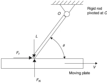
As to Sprag-slip, it occurs for a friction system where one of its objects has an angled counter force against the other moving object and, consequently, making both the surfaces of the objects to sprag and slip in succession; or, sometimes, even interlock the two objects (Figure 7.2) [7]. At what angle θ that sprag-slip starts to occur at is defined as when θ approaches
µ = cot 𝜃 (2)
where µ is the friction coefficient. To mathematically explain why this is, consider a ridged rod that pivots at O and rests against a moving plate (Figure 8). By taking the
moment at O, while assuming that µ=Ff /FN, one will arrive at the two equations
(appx.1)
𝐹! =!!! !"# !! ! (3)
𝐹! =!!! !"# !! (4)
The equations shows that when the angle θ approaches µ=cot θ, both Ff and FN
approaches infinity, which is when sprag-slip starts to happen. In general, this is also known as geometrically- induced or kinematic constraint instability [5].
Figure 7.1 Stick-slip Figure 7.2 Sprag-slip
k Ff F v m 7.1 θ Ff F v 7.2
Theoretical framework
2.3 Levers
A lever is a bar that is fixed at one point and can rotate around it. That point is called the fulcrum. Levers can be used for lifting loads in an advantageous way. There are three classes of levers [8].
A Class 1 lever has the load on one side of the bar, a downwards-applied force on the other side and the fulcrum in between them. A seesaw is an example of a Class 1 lever.
A Class 2 lever has the fulcrum on one side of the bar, an upwards-applied force on the other side and a load in between them. A wheelbarrow is an example of a Class 2 lever
A Class 3 lever has the fulcrum on one side of the bar, the load on the other side and the applied force in between them. A stapler is an example of a Class 3 lever
Force
Fulcrum Load
Figure 9 Class 1 lever.
Force
Fulcrum Load
Figure 10 Class 2 lever.
Force
Fulcrum Load
Theoretical framework
2.4 The friction test machine
2.4.1 Hardware2.4.1.1 Bearings
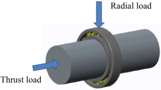
Bearings are devices that enable rotational and linear movements with low friction. They consist of an internal and external metal ring where either balls or rollers can be accommodated in between them. These rings will be able to rotate by the help of the balls/roller that is in between them. When in use, bearings can be exposed to two kinds of loads: radial load and thrust load (Figure 12) [9].
Different types of bearings have been engineered to withstand different amount of radial load, thrust load, and rotational speed [9]. The two bearings used in this machine are deep grove ball bearings with a single row of bearings (SKF 6203-2Z).
2.4.1.2 Actuator
An actuator is a mechanical device that can convert electrical, pneumatic or hydraulic energy into mechanical energy [10]. The actuator used in this work uses electricity to create its mechanical movement. Actuators convert electrical energy into mechanical energy by employing Lorentz’s force law. The Lorentz’s force law states that when a conductor with an electric current flowing through it moves through an electric field, a force will as in result be created. The force is the product of the current and the magnetic field
𝐹 = 𝐼×𝐵 (4)
where 𝐹 is the force vector, 𝐼 is the current’s vector and 𝐵 is the magnetic field’s
vector. The relation of these vectors directions can be explained by using the right hand rule. The right hand rule states: if the index finger is pointing in the direction of the current vector, while the middle finger points in the direction of the magnetic
Radial load
Thrust load
Theoretical framework
field’s vector, then the thumb will, because of the autonomy of the hand, be pointing in the resulting force vector’s direction, i.e., perpendicular to the index finger and the middle finger [11].
Electric motor actuators can either be classified by function or by electric configuration. The electric motor actuators can then have different mechanical components installed onto it, each of which results in different types of motions [11]. The actuator used in this work (LEFS32A) is, for example, an electric motor actuator with a DC servo stepper motor and with a ball screw drive installed with it. Servo and stepper are two functional classifications, DC is the electric configuration
classification and the ball screw drive is the mechanical component that enables the actuator to create a linear motion. The actuator can be bought with different ball screw lengths, which directly affects how long the actuator’s linear motion is. The actuator in this work has a 320mm long ball screw drive [12].
A servomotor is a motor that is combined with a position-sensing device (e.g., a digital encoder). By the help of this device and a programmable controller, the motor can accurately change its position according to the controller’s given programming. This is called a close loop control since the position-sensing device always feeds back data to the controller [11]. In this work, the computer that the actuator is connected to acts as the controller.
A DC motor is powered by a direct current electrical charge and can respond very fast because it has a high ratio to torque, and rotor inertia. A DC motor that rotates by rotating in several angular incensements, also known as steps, is called a stepper motor. How many steps the motor uses for one revolution varies but ranges from 12 to 200 steps. Other characteristics of stepper motors are that they are able to rotate in both the directions and can sustain a torque when it does not rotate [11].
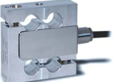
2.4.1.3 Load cell
A load cell is a sensor that can measure mechanical force by using a strain gage and a Wheatstone bridge circuit. The strain gages are installed inside the load cell and on top of flexural elements. These strain gages are then connected to a Wheatstone bridge circuit. Which then, together, are excited with a voltage from an input wire. When a mechanical force is applied on the load cell, the strain gage will flex along with the flexural elements and, because of that, change its electrical resistance. The bridge circuit will then in return sense this and a new voltage value will be emitted
Theoretical framework
from the load cell through an output wire. These two values in each of these wires can then be measured and compared. The difference in the two voltages is directly
proportional to the strain gage’s deformation and to the force that was applied. Different load cells are dimensioned to measure different amounts of loads [11]. The load cell used in this work is a TCA 25kg Vetek load cell and can measure loads up to 25kg.
2.4.1.4 Thermometer
If two dissimilar metals (metal A and metal B) are joined together, creating a
thermoelectric junction, a voltage will be produced at this junction that is proportional to the junction’s temperature (Figure 13). This is known as the Seebeck effect. In order to measure the produced voltage at the junction, an electric circuit must be created; therefore, another junction is added in with the junction to close the loop. These two junctions together are known as a thermocouple (Figure 14). The voltage in the thermo couple circuit is defined as
𝑉 = 𝛼(𝑇! − 𝑇!) (4)
where V is the voltage, α is the Seebeck coefficient, T1 is the temperature of one of
the junctions, and T2 is the temperature of the other junction. The produced voltage of
the thermocouple will differ depending on what metals the thermocouple is made up of [11].
2.4.2 Software
2.4.2.1 LabVIEW
LabVIEW is a programming software that is created by Nation Instruments and is defined by them as:
Picture 3 TCA 25kg load cell, Vetek.
Theoretical framework
“[A] highly productive development environment for creating custom
applications that interact with real-world data or signals in fields such as science and engineering.”
The LabVIEW software uses the G programming language (G as in graphical) and is a central part to what LabVIEW is. It designed to be used by engineers and scientists and aims to be as simple and intuitive for the user as possible by featuring a graphical user interface. The software is compatible to communicate with a majority of
hardware [13].
Both the actuator and the load cell used in this work are connected to a computer that uses LabVIEW to start and stop the actuator and to receive the yield voltage from the load cell.
2.5 Product development
2.5.1 Function breakdownWhen a new product is being developed, having several criteria for the concept of the product is of importance. Initial criteria are given at the start of a product development process but new criteria might also arise during the development process; this is because more information has during the time been collected. These criteria together are called the specifications of the product’s concept.
The specifications make up a good descriptive picture of what the concept should feature and be capable of. However, it is not easy to be used as aims in the
development process because it is only a general picture of the product concept. A way to solve this is to convert the specification in to functions and treat each function as a separate aim that should be fulfilled in the development process. Such conversion is known as a function breakdown. The functions are described in a verb + noun + limit format and are divided into four different types [14]:
Main functions – The function that makes up the whole purpose of the product. Products usually only has one main function.
Support functions – The functions that might ease or aid the usage of the product (or the manufacturing of it etc.) without affecting the main function.
Partial functions – These functions together make up the main functions. Undesired functions – Side effects or unwanted functions that are inevitable. A partial function for a car could for example be “Carry load, 500kg”.
2.5.2 Brainstorming
A way to come up with ideas for anything is to use brainstorming. Brainstorming should be done by a group of people and relies solemnly on that group’s knowledge and creativity. The aim for this group is to create as many ideas as they can imagine and as fast as they can. No one should criticize anyone else’s idea and coming up with
Theoretical framework
ideas out of the ordinary should be encouraged. Ideas can then in the process be combined to generate more new ideas [14].
2.5.3 Morphological matrix
At the stage when several ideas for a product’s functions exist, a morphological matrix can be used. All of the ideas are added into the matrix and can then, freely, be combined with each other and together create a complete product concept. The ideas can be combined more than once and each time in different ways and, by that, creating even more product concepts [14].
2.5.4 Go/No-go elimination
The first step after generating concepts in a product development process is to use a go/no-go elimination. This kind of elimination eliminates the less optimal concepts among all of the concepts by validating how well each of the concepts fulfills each of these six criteria:
• Solves the main problem • Fullfills the requirements • Feasible
• Fits within the budget/Reasonable expensive • Safe and ergonomic
• Enough information
The elimination is often done in the form of a matrix. A concept that passes a criterion will be marked with a plus sign (+) for that criterion. If it does not pass the criterion then it is marked with a minus sign (-); or, if the concept lacks enough information in order to give it a good judgment, it will be marked with a question mark (?). All of the marks are then compiled to together to make up the decision of whether a further development of the concept will be carried on or not. Comments can also be given to each of the concepts as descriptions for their resulted marks [14].
2.5.5 Crap-up & Prototype
A crap-up and a prototype are both created during a product development process and both serves almost the same purpose.
A crap-up is built up by anything, often referred as “crap”. The crap-up is meant to recreate the functionality of a concept but not necessarily its visual appearance. Crap-ups are created in an early stage of a product development process and aid the process of refining the functionality of the product concept before developing it further, thus, saving both money and time.
Prototypes are, on the other hand, as alike the real product as it can be and is usually done at the end of the developing process. They help finding the last refineries the product might need before it actually can be produced [15].
Analysis and concept development
3 Analysis and concept development
The work in this report started of by first studying the machine so that a profound understanding of its hardware and software could first be inquired. Then, proceeded by analyzing why the noise, vibration problem occurred and then, ultimately, creating a new construction design that can solve the problem along with making it correspond to its specifications.
The machine was studied by learning about its software, electrical wiring and
electrical components, that is, the actuator and the load cell. When the understanding of these was inquired, it all was documented by taking photos of the machine (appx. 2), illustrating the machine in the CAD software SolidWorks (appx. 3), creating a wiring diagrams for its electrical wiring (appx.4), and saving its original labview programming code (appx. 5). Along all this, the field of tribology and friction test machines was studied as well, because of its high relevance for the machine. The noise, vibration problem was analyzed by performing random tests. The results from the random tests were then interpreted. The purpose of this was to find the source for this problem and by that also knowing how to solve it. The original labview G code were not programmed with a friction force indicator, which showed how much friction force the load cell was censoring. This was important to have when analyzing the problem because it enabled one to sense the whole picture of the problem. A friction force indicator was therefore added to the G code and was also verified to function correctly (appx. 6).
As soon as the cause of the noises and vibrations was found, the development of a new construction design was carried out. The secondary problem of the machine was its incongruity with its specifications. So, while the machine anyway was being reconstructed for the purpose of solving the noise, vibration problem, the
specifications were also taken into consideration by integrating them to the process. As mentioned in the background subsection of this report, it had been decided that some specifications would not be fulfilled; and that some were adjusted due to time limitation and to make the work less extensive.
3.1 Analyzing the noises and vibrations
3.1.1 Random testsThe purpose of this step was for the author to look at the noise, vibration problem for himself. The experience gathered this way would then create a general picture of the noise, vibration problem. When the general picture of the problem had been created, the problem was interpreted and analyzed doing an analogy with similar problems.
Analysis and concept development
To execute several random tests with the machine became the first starting point in the aim of looking at the machine’s noise, vibration problem and understanding why it was happening. Two flat specimen and three pin specimens was in total used for all the executions. The two flat specimens were made out of gray iron, one of the pin specimens were made out steel, one out of gray iron and one had a bearing ball on its tip. The pin with the bearing ball was used more than once (Picture 4).
When the test was executed, they all had different test settings i.e. what speed the flat specimen oscillated in, how long the distance of the oscillations were, the duration of the oscillation and also what materials that they reciprocated against each other with. The same 47,7N load was however used for each of the tests.
In the beginning of very test, it was assured that both the pin specimen and the flat specimen were tightly fastened to their respective places. When they were tightly fastened, the foldable arm was folded down, and the load was placed on the arm, making the specimens being forced against each other. The arm had a horizontal position at this point (picture 1).
When the specimens were fastened and forced against each other, the actuator was turned on; and, by that, initiating the oscillating friction movement between the two specimens. Because of the combination of both the specimens being pushed against each other and at the same time oscillating, they started to wear out each other. What all the tests more or less had in common were that they; yes indeed ended up creating noises and vibrations. It was heard that the noises came from the specimens wearing interaction and it was felt that it was the foldable arm that was vibrating the most.
Picture 4 The five specimens used for random test
experiments. The one in the bottom of the picture is unused.
Analysis and concept development
Another observation was that the steel and the gray iron pin specimens had gained tilted wears during their tests. To gain tilted wears was implicitly known in this work as an undesired test result. It was undesired because that would make calculating the wear volume more difficult, than compared with a non-tilted wear.
In every test, the load cell had been mounted next to the pin specimen, recording the friction forces in both the oscillating directions. The load cell showed to record larger forces in the direction towards the arm base than in the direction away form the arm base (It was in the direction to the arm base that the noise, vibration problem
occurred).
The following bulletin point summarizes what had been observed at the random tests: • It was the arm that vibrated when vibrations occurred
• It was from the friction interaction of the specimens that made the noises • The friction forces recorded by the load cell was not the same in the two
oscillating directions
• The pin specimens were gaining tilted wears during the tests 3.1.2 Interpreting
Here, the observations from the random tests are interpreted.
The general picture that had been obtained during the random test was that the ability of the foldable arm to gain a folding angle was somehow the source to the vibrations and noises. During the tests, the pin specimen seemed to be “digging” into the flat specimen while moving towards the arm base, while in the other direction, the pin specimen was sliding on the flat specimen more gently, like a nail would do on a gramophone.
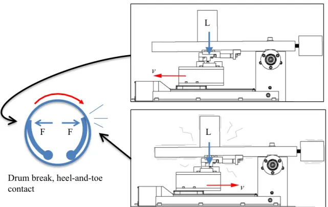
It was speculated that an analogy between the noises and vibrations of the machine and the squeals of a drum break could be made; because, like the shoe in some drum breaks might oppose the rotation of the drum when in a heel-and-toe contact [7], so did the pin specimen appear to do against the moving flat specimen. Figure 15
demonstrates this analogy where the force F for the drum break is the analogy to what the load L is for the machine.
Analysis and concept development
A literature study was performed in the field of drum breaks when this analogy was made. After the research, it appeared that this kind of problem is within the field of friction-induced vibrations.
Two friction induced vibration phenomenon, believed to be the explanation to the noises and vibrations of the machine, was extracted from the literature study. The first one was stick-slip and the other one was sprag-slip. These were then compared with the machine.
Starting with stick-slip. Stick-slip is defined to happen to slow moving friction systems when the static coefficient of friction is higher than the kinetic coefficient of friction. The machine did only manifest the noises and vibrations in one direction. If stick-slip would be what was happening to the machine, the noises and vibrations should have appeared in both the directions. Stick-slip was therefore deemed to not be the explanation to the noises and vibrations of the machine.
Proceeding to sprag-slip. Sprag-slip is defined to happen when the objects are angled against each other as they move and as they approach
µ = cot 𝜃 (2)
Where µ is the coefficient of friction and θ is the angle. Figure 16 shows where the angle θ of the machine is. This angle θ was measured to be about 3,3° in the CAD illustrated version of the machine. Then, by applying the 3,3° in equation 2, the resulting coefficient of friction µ becomes equal to about 17,4. The specimens’ coefficient of friction µ was not near that. Hence the noises and vibrations of the machine could not be addressed as being a sprag-slip case.
L
L F
F
Drum break, heel-and-toe contact
Analysis and concept development
However, the sprag-slip definition had shed light on the angle θ of the machine and that it should be considered. By taking the moment about O, like the explanation to sprag-slip had done, and observing the two resulting equations
𝐹! =!!! !"# !! ! (3) 𝐹! =!!! !"# ! ! (4)
, one could draw the direct conclusion that Ff ≠ µL and FN ≠L in the machine, which is
the contrary to what has been believed up until this point, i.e., Ff =µL and FN=L. What
this in other word implied was that, when the actuator moved towards the arm base, the force cell installed on the foldable arm was recording the friction force !!! !"# !! !
and that an upwards force of 𝐿 !
!!! !"# !− 1 was constantly being induced on the
arm, causing the arm to vibrate (Figure 17). This was deemed to be the explanation for the noises and vibrations of the machine. A possible solution for this would be to reconstruct the pivot point to a position where the angle θ is equal to 0°.
↑ : 𝑂! = 𝐿 1
1 − µ tan 𝜃− 1
← : 𝑂! = µ 𝐿
1 − µ tan 𝜃
Figure 16 The angle θ in the friction test machine. O is the pivot point of the
arm and P is the frictional contact point.
Figure 17 Deemed reason to why the noises and vibrations occurs. The weigh of the arm
Analysis and concept development
Simply making θ = 0° by reconstructing the pivot point was a possible solution to the vibration, noise problem; but, in that case, the recently discovered problem of the pin specimen gaining a tilted wear would still be occurring. A more desirable solution would instead be to substitute the pivot point O with a point Q that only have a horizontal degree of freedom (DOF). The angle θ would in that case be irrelevant. (Figure 18)
↺ 𝑄: 𝐹!𝑑 = −𝑀!
↑ : 𝐹!= −𝐿
← : 𝑄! = −𝐹!
The force diagram in figure 18 was settled to be the theoretical solution for the noise, vibration problem. This theoretical solution would be integrated into the development of a new construction concept.
3.2 Development of a new concept
This subsection presents the development of a new construction concept that solves the noise, vibration problem along with fulfilling the specifications for the machine. A step-by-step approach was done in the development process (Figure 19).
3.2.1 Function breakdown
In this first step of developing a new construction concept of the friction test machine, a functional breakdown was developed. As given in the objective, the aim was to
Figure 19 The steps of creating a reconstruction concept.
d QX v Ff Q P L MQ FN
Analysis and concept development
solve the noise, vibration problem while making the machine correspond with the specifications. To do so, the machines specification and the theoretical solution were converted into a function breakdown table. This table acts as the foundation for both the coming brainstorm session and the morphological matrix.
Function breakdown
Function type Verb Noun Limits
MF Obtain Metallic
tribological data
PF to MF Measure (1) Friction force Up to 120 N
PF to MF Measure (2) Specimens’
temperature
PF to MF Measure (3) Test duration Up to 48 hours
PF to MF Generate Load Up to 120 N
PF to MF Oscillate Specimens Up to 90mm, oscillate
according to theoretical solution
PF to MF Accommodate Lubrication
PF to MF Attach (1) Pin specimen 1 Piece. Ø5-10mm,
15-20mm long. Uniformly
PF to MF Attach (2) Flat specimen 1 Piece with length
30-100mm, width 15-35mm and thickness 8-15mm. Uniformly
Tabel 4 Function breakdown of the wear machine. (Main function MF, Partial
function PF)
3.2.2 Brainstorm
A brainstorm session was done in order to find at least one idea for every partial function in the function breakdown table. All the ideas were sketched down with pen and paper. These ideas were then used in the morphological matrix.
3.2.3 Morphological matrix
All the ideas generated from the brainstorm session were added into a morphological matrix, arranging the ideas in columns and the partial function, which the ideas were supposed to solve, in rows (Figure 20). In order to create new concepts, partial
functions were mixed and matched. Certain combinations were chosen. This was done three times, which resulted in three concepts.
Theoretical solution The machine’s specifications
+
Analysis and concept development
Morphological matrix
Product designation: Tribological test machine
Partial function Idea 1 Idea 2 Idea 3 Idea 4
Measure friction force, up to 120 N (Current method) Measure specimens' temperature Generate load, up to 120 N Oscilliate specimens, 30-100mm, oscillate according to theoretical solution Accomodate lubrication Attach pin specimen, 1 Piece. Ø10mm, 15-20mm long Attach flat specimen, 1 Piece with length 30- 100mm, width 15-35mm and thickness 8-15mm. Legend Concept 1 Concept 2 Concept 3
Analysis and concept development
3.2.4 Go/No-go matrix
A Go/No-go matrix was used to sort out the most optimal concept out of the three concepts created in the morphological matrix step (Figure 21).
According to the results of the Go/No-go matrix, concept 2 was the concept that should be further developed. Concept 1 did not perform well under the “Reasonable expensive” part of the matrix because the pneumatic table partial function of the concept was considered to redundant. The money and the effort that the pneumatic table requires would probably not yield much better results in comparison with the other concepts that instead had a rolling mechanism. The rolling mechanism was also considered to be a more simple idea. Concept 3 received a bad rating under the “Safe and ergonomic” part because of its free hanging weight partial function. The free hanging weights was considered to not be ergonomic and especially not when compared to the other concepts idea within that partial function i.e. having a lever mechanism.
3.2.5 Crap-up
To assure that the selected concept 2 would work physically, a crap-up of the concept was made.
Figure 21 Go/No-go matrix of the three concepts.
Comments Decision 1 + + + - + + The penumatic table is redundent -2 + + + + + + + 3 + + + + - + The free weights are not ergonomic - En ou gh in fo rmati on Go/No-go matrix: Tribological test machine Elemination criterias: (+) Yes (-) No (?) More info is needed (!) Check procuct specificion Decison: (+) Carry out the solution (-) Eliminate the solution (?) Search for more info (!) Check procuct specification Co ncep t So lves th e mai n p ro bl em Fu lfi lls a ll th e re qu ire m en ts Fe as ib le Re as on ab le e xp en si ve Safe an d ergo no mi c
Analysis and concept development
Cardboard, paper and tape were used to create the up. The purpose of this crap-up was to evaluate if the concept would work physically by achieving a sense of its partial functions in a physical form (Picture 4).
An evaluation of the concept crap-up was done as soon as the crap-up had been created. All of the partial functions seemed to be able to function properly, except for the sliding bar unit. The sliding bar unit of the concept crap-up did not seem to be able to function properly because it looked like to easily would start tilt when it would be oscillated by the actuator (Picture 5). Examples of consequence this could lead to is lever forces being lost because of friction forces from the sides it tilts against, or the specimen’s surfaces receiving irregular wears.
The consequences that could arise from the tilting of the sliding double rod unit were not acceptable. Having load force lost to friction in this way would make it hard to fulfill the partial function of creating load forces up to 120N. Therefore, it was decided that the sliding double rod unit in the concept crap-up had to be swapped for something else.
Oscillating movement, v Sliding bar unit
Fulcrum unit Force from the lever, L
Load Lever
Analysis and concept development
A runner unit was selected to be the new unit that the sliding bar unit would be substituted with. The runner unit consisted of a runner that, in contrast to the bars of the sliding bar unit, was a standard manufactured part. A much more linear motion with minimum influence from friction was possible with this unit because of its fine-engineered bearing ball sliding mechanism. Hence, load force lost due to friction and irregular wears on the specimens was not expected to happen with this new selected unit
Picture 6 Crap-up of the concept with a runner unit. Picture 5 Scenario when the sliding bar becomes tilted
Analysis and concept development
The concept crap-up with its new runner unit was again created, but this time out of SikaBlocks. The purpose for recreating it in SikaBlocks was to make the concepts’s function even more defined. Having the concept more defined in the form SikaBlocks made it easier to do an even better evaluation of the concepts conceptulaized functions (Picture 7).
The concepts functions was again evaluated. Except for the height of the fulcrum unit (originally known as the arm base unit), all of the conepts partial funtions seemed to function as they were intended to. The height of the fulcrum unit became too low when the runner unit was selected to swap place with the sliding double rod unit. This issue was decided to be taken cared of in the next step where the concept would be illustated in the CAD software SolidWorks
3.2.6 CAD
The concept in its final crap up form was measured and recreated in SolidWorks (Figure 22). In the proces of doing this recreation, the parts geometry became simplified and minor various design gaps that had not been defined in the concept became defined. This can be observed by looking at the parts from the SikaBlock crap-up of the concet in appendix 7 and the eqvivilent parts in the CAD version of the concept in appedix 8.
Aluminum is what most of the designed components was assigned to be made out of. The two components that had their material assigned more accurately was the
balancing weight and load weight. This is because their density mattered in order for the lever of the concept to function properly.
Analysis and concept development
Figure 22 Concept created in SolidWorks. The yellow cylinder, made out of brass, is
the load weight and the other thick gray cylinder, made out of steel, is the balancing weight.
Discussion and conclusion
4 Concept evaluation
4.1 Concept VS function breakdown
In this section, the developed redesign concept is compared with the function breakdown table. It is compared one by one to see how well each of the partial functions of the table was fulfilled by the concept. The partial functions are presented as subheadings down below and are arranged in the same order as they are in the function breakdown table.
4.1.1 Measure friction force
The first partial function was to read friction forces up to 120 N. The concept was designed to be able to do this by installing the original load cell on one side,
connected to a fixed block, and on the other side mounted onto a platform that rests on several bearing balls. On the platform, the interaction between the two specimens takes place by having the flat specimen fasten on the platform and the pin specimen oscillating against it. The friction created from the interaction of the specimens pushes the whole table construction with the flat specimen with an equal force. The load cell then, in return, records that.
The connection of the load cell with the fixed block is not fully fasten but instead has a narrow gap by the help of a prevailing torque nut on one side. The narrow gap was designed in order to assure that the load cell only reads the friction force and no moment.
Narrow gaps
Figure 23 The friction measurement set up.
Load cell
Discussion and conclusion
4.1.2 Measure specimens temperature
This partial function required the concept to be able to measure the specimens’
temperature at the interaction point. To fulfill this, the concept had been featured with a small hole in the pin specimen’s fixture where a thermocouple wire could pass through and then be wired onto the pin specimen. In this way, the thermos couple wire can measure the pin surface temperature, which is about the same temperature that both the specimens receive when the friction occurs. The wire is then secured by a wing nut. When securing it, only the fixture and the wing nut must touch the lining of the wire.
4.1.3 Measure test duration
This partial function needed the concept to be able to measure the test duration up to 48 hours. The labview G code of the machine had already been programmed to measure the test duration from the very beginning. Therefore, it was reused in this reconstruction concept.
4.1.4 Generate load
This partial function required the concept to have the ability generate a load up to 120N. To fulfill this, a lever design was employed to create an adjustable load on the pin specimen. It consists of a lever with a sliding 60N brass load on it. By sliding the load to any of its possible positions on the lever, it can create a load from 3,5N up to 120N on the specimen. It cannot create a load below 3,5N because of the runner unit’s dead weight (Figure 25). Because the runner unit is always located at the same
position along the length of the lever, the same force will always act on it as it oscillates (Figure 26). An indicator is marked on the bar to show how much force the load is generating on the pin specimen (Figure 27). The solution was seen as very suitable because of its simplicity and inexpensiveness.
Figure 24 Thermocouple wire and the pin specimen.
Thermo couple wire
Thermometer
Discussion and conclusion
4.1.5 Oscillate specimen
In this partial function, the limits were that the specimen would have an oscillation distance up to 90mm while oscillating according to the theoretical solution.
Figure 25 The lever mechanism of the concept.
Figure 27 Even load on the runner unit
Discussion and conclusion
The original actuator reused in this concept and was capable of performing the 30mm up to 90mm, making that limit of the partial function being fulfilled (Figure 28).
Installing a runner vertically on a fixture that connected the runner and the actuator fulfilled the second limit. Figure 29 compares the theoretical solutions force diagram with the concepts force diagram.
4.1.6 Accommodate lubrication FN v Ff Q P L MQ d QX
Figure 29 The theoretical solution and the concept.
d QX v Ff Q P L MQ FN Figure 28 Oscillating up to 90mm. 90mm Actuator
Discussion and conclusion
The concept solved this partial function by including a lubrication bath in the design. The bath itself was designed to have a rim height of 20mm, making it 5mm higher up than the largest set thickness of the flat specimen, which is 15mm. (Figure 30).
4.1.7 Attach pin specimen
This partial function needed the concept to be able attaching a pin specimen with the dimensions Ø5-10mm and 15-20mm in length in a uniformed way. The concept was designed with a Ø11mm hole where a pin with any of those diameters can be inserted and fasten by a bolt. The pin used should, according to the concepts idea, have a semi cylindrical form at the fastening point in order to achieve the desired uniformed attachment (Figure 31)
4.1.8 Attach flat specimen
Figure 31 Section view of the bolt and the pin specimen.
Bolt Pin specimen
Figure 30 Flat specimen inside the lubricant bath.
5mm Tub
Flat specimen
Discussion and conclusion
This partial function required the concept to be able to attach a flat specimen with the dimensional range of: length 30-100mm, width 15-35mm and thickness 8-15mm, along being able to attach it uniformly, and being able to do three different tests on the same side of the flat specimen. The concept was designed with an adjustable “stair” block that enabled these perquisites. The stair block can slide along the platform’s two slits and be fasten by screwing the wing nuts. By the help of the block’s three stairs, the flat specimen can be clamed in three uniformed ways (Figure 32).
Figure 32 Three possible tests on one 35mm wide flat specimen.
“stair” block Flat specimen
![Figure 1 A descriptive illustration of the standard test method ASTM G133 [15].](https://thumb-eu.123doks.com/thumbv2/5dokorg/5391533.137636/9.892.150.746.674.1060/figure-descriptive-illustration-standard-test-method-astm-g.webp)