A Review of the Decommissioning
Costs of the Ranstad Site
Research
Authors: Geoff Varley, NAC International Date: August 2009.
This report concerns a study which has been conducted for the Swedish Radiation Safety Authority, SSM. The conclusions and viewpoints pre-sented in the report are those of the author/authors and do not neces-sarily coincide with those of the SSM.
SSM perspective
Background
A demanding task for the present generation is to assure that appropria-te financial resources are injecappropria-ted into the Swedish Nuclear Wasappropria-te Fund. It will thereby be possible for coming generations to undertake efficient measures in the decommissioning and dismantling of older nuclear fa-cilities. To undertake such measures in line with the environmental and health codex is essential.
Assuring that enough financial provisions are set aside to balance these future environmental liabilities is essential to demonstrate the sustaina-bility and long term credisustaina-bility of the financing system that underpins Sweden’s nuclear waste liabilities.
A deficit situation must be avoided, so it is of utmost importance that cost estimates are prudent and made with a high level of precision. To secure this quality in the estimated costs for individual nuclear facilities that are candidates for decommissioning and dismantling, SSM is un-dertaking a systematic review of these estimates. Some of these reviews are made by external and independent resources.
Purpose of the project
The main objective of this study has been to review the future cost to decommission and dismantling the industrial area at the site of the old uranium mine at Ranstad in Sweden.
Analyses of some detailed comparative empirical information have been used in the context of preliminary “bench-marking” studies. The estima-ted costs for decommissioning of the old uranium mine in Ranstad have been compared with actual costs from other relevant decommissioning projects. In this way it has been possible to give a preliminary qualitative statement about the accuracy of the Ranstad cost estimate.
1. The available information suggests that the overall estimated cost may be reasonable, but there are still some points of weakness that need to be elaborated more in detail before a full statement about the adequacy of the forecast cost will be possible.
2. Especially the costs associated with declassification activities war-rant further analysis in order to determine there level of accuracy. 3. There exists the possibility that the estimate might be low concerning
decontamination, dismantling and planning and institutional work. 4. Further work and analysis is needed in order to develop a more
transparent cost estimate in which the stakeholders can have the highest confidence.
5. A new bidding procedure for the conventional demolition may re-sult in lower estimated costs. Hence, it would be beneficial to obtain an updated estimate based on at least more than one quotation. 6. The method of addressing uncertainty and risk should be more
connected to the logistics of specific decommissioning activities, in orer to be more transparent and clearer in details.
Continued work
There is a need for further study to develop a better estimate. In the short run follow-up work needs to be undertaken to provide a better under-standing of what are the major contributors to risk and costdrivers in the planned decommissioning process at the Randstad industrial.
Effects on SSM work
SSM will be able to use the study as supporting documentation in the review of the estimates given for the decommissioning costs of the nu-clear facilities that are governed by the Studsvik Act.
Project information
At SSM Staffan Lindskog has supervised and co-ordinated the project. Likewise, at NAC International Geoff Varley has performed the research task with determination and skill.
Contents
1. Introduction ... 1-1
2. Description of Facilities for Decommissioning at
the Ranstad Site ... 2-1
2.1 Large Leaching Hall... 2-2 2.2 RMA Leaching Hall ... 2-5 2.3 Old Sorting Facility ... 2-10 2.4 Control Building ... 2-13 2.5 Lime Silos ... 2-14 2.6 Heating Plant Building ... 2-15 2.7 Transformer Building ... 2-16
3. Decommissioning Plan Information ... 3-1
3.1 Decommissioning Scope ... 3-1 3.2 Decommissioning Methods/Approach ... 3-2 3.3 Decommissioning Cost Estimate ... 3-2 3.3.1 Cost Breakdown by Activity ... 3-2 3.3.2 Principal Uncertainties... 3-3
4. Comparisons with Relevant External
Benchmarking Results... 4-1
4.1 Planning and Institutional... 4-1 4.2 Radioactive Characterisation... 4-2 4.3 Decontamination... 4-3 4.4 Equipment Dismantling... 4-4
5. Preliminary Opinion on Reasonableness
Figures/Tables
Figure 2-1 Overview of the Ranstad Site... 2-1 Figure 2-2 Interior Overview of Large Leaching Hall Pools... 2-2 Figure 2-3 One of Four 25m x 25m Large Leaching Hall Pools... 2-3 Figure 2-4 Processing Equipment in Basement of Large Leaching Hall Building ... 2-3 Figure 2-5 Basement of Large Leaching Hall Showing Liquor Management Pipework ... 2-4 Figure 2-6 Overview of RMA Leaching Hall Showing Percolation Leach Tanks in Foreground 2-5 Figure 2-7 RMA Leaching Hall Showing Storage Tanks in Background ... 2-5 Figure 2-8 Example of Acid Resistant Tiled Floors... 2-6 Figure 2-9 Tanks Used in Second Stage of Floculation Process... 2-6 Figure 2-10 Filter Press for Leaching Residues ... 2-6 Figure 2-11 ADU Precipitation Tanks (not in use) ... 2-7 Figure 2-12 Liquid-Liquid Extraction in Mixer-Settlers ... 2-7 Figure 2-13 Storage Tanks... 2-7 Figure 2-14 Mid section of Percolation Leaching Vessels ... 2-8 Figure 2-15 Filter Press – Water Cleaning ... 2-8 Figure 2-16 Drying Equipment for Leaching Residues ... 2-8 Figure 2-17 Pre-Crusher for Ashes ... 2-9 Figure 2-18 Mill for Ashes... 2-10 Figure 2-19 External View on Old Sorting Facility ... 2-10 Figure 2-20 Magnetite Slurry Pools in Old Sorting Facility ... 2-11 Figure 2-21 View Showing Substantial Concrete Structures of the Old
Sorting Facility Building ... 2-12 Figure 2-22 Control Room and Elevated Gantries/Walkways inside the Old Sorting Facility.... 2-12 Figure 2-23 Dust Collecting Tanks in Old Sorting Facility... 2-13 Figure 2-24 Control Building with Lime Silos in the Background ... 2-13 Figure 2-25 One of the Basement Rooms in Control Building ... 2-14 Figure 2-26 View Under Lime Silo ... 2-14 Figure 2-27 View of Concrete Lime Silos ... 2-15 Figure 2-28 External View on Disused heating Plant Building ... 2-16 Figure 2-29 Internal View of Disused Heating Plant Building... 2-16 Figure 2-30 Transformer Building ... 2-17 Table 3-1 Approximate Breakdown of Cost Estimate by Category of
Decommissioning Activity... 3-3 Table 4-1 Breakdown of Estimated Decontamination Costs... 4-4
1.
Introduction
The Ranstad Industriecentrum AB (RIC) in Sweden hosts a range of facilities formerly used for the processing of natural uranium bearing alum shales mined from nearby deposits. Most of the facilities are no longer in use and some cleanup activities already have taken place. One of the facilities continues to be used actively by Ranstad Mineral AB (RMA), namely, a chemical processing facility for the recovery of uranium from wastes generated by nuclear fuel manufacturers. The recovery includes the handling of enriched uranium and is classified as a nuclear facility. RMA also makes use of space in older facilities for temporary storage of untreated wastes and processed wastes.
The longer term commercial future of RIC in most uncertain1. Today the future of RMA also is uncertain – at least its continuity over the long term - because the workforce in total is very small and the management team comprises essentially just one person. SKI, now subsumed into SSM, therefore has taken a specific interest in the plans for and financing of the decommissioning liabilities associated with RIC and RMA. It is
necessary to establish a reliable estimate of the cost for ultimate decommissioning and to establish a clear basis for the funding of such activities.
A report on the costs of decommissioning certain buildings and facilities at RIC, including an updated estimate of the total cost, was prepared in June 2008 by SKB International Consultants AB (SKB IC) – see reference 1. SKB IC is a wholly owned subsidiary of the Swedish Nuclear Fuel and Waste Management Company, or Svensk Kärnbränslehantering AB (SKB). NAC International has been commissioned by SKI to review this latest estimate and to provide an expert opinion on its reasonableness. In support of this task, a visit to the RIC site was made in July 2008 and all buildings included in the decommissioning estimate were inspected.
This report provides preliminary opinions on:
The assumed overall logistics of the decommissioning effort, including the
methodologies assumed to be applied and the extent to which these represent current/best practice
Analysis of estimated costs for the various parts of the decommissioning program, including comparisons with relevant external decommissioning references. The budget available for this work necessarily has constrained the level of detailed investigation and analysis possible at this stage.
2.
Description of Facilities for
Decommissioning at the Ranstad Site
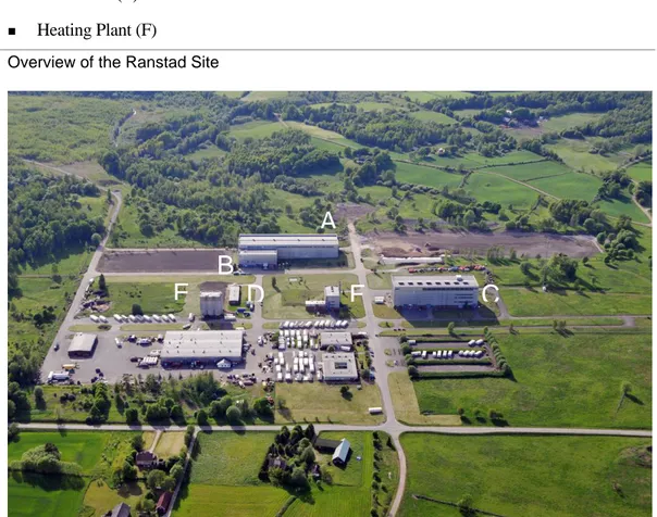
An overview of the RIC site is presented in Figure 2-1. It shows all the main facilities included the SKB decommissioning cost estimate, as follows: Large Leaching Hall (A) RMA Leaching Hall (B) Old Sorting Facility (C) Control Building (D) Lime Silos (E) Heating Plant (F)
Figure 2-1 Overview of the Ranstad Site
A
B
E
D
F
C
The disused transformer building is outside the range of this photograph. Other facilities on the site have been transferred to other businesses, are deemed to be clean and are not part of the scope of work described in the SKB cost estimate.
2.1
Large Leaching Hall
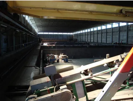
A selection of photographs of the inside of the large leaching hall facility is presented in Figure 2-2 to Figure 2-5. The large leaching hall is of concrete construction
approximately 120 long by 38m wide and 18m high. The estimated concrete volume for dismantling/demolition is estimated to be just over 3,500 m3 weighing just over 7,400 tonnes.
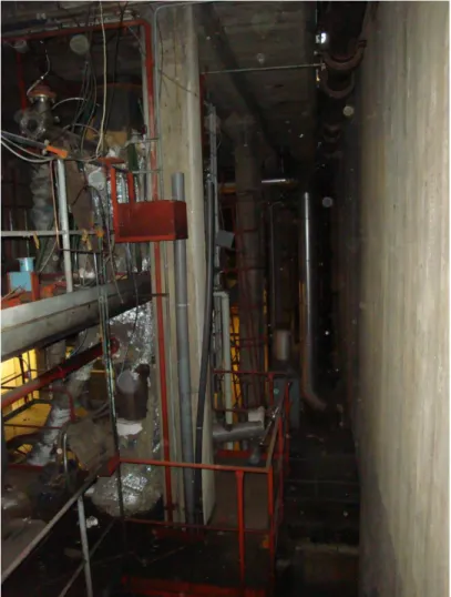
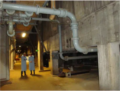
The pools, each about 25m x 25m in area and approximately 4 to 5m in depth are lined with acid-resistant brick. Sulphuric acid was used in the pools to leach uranium from the feedstock of prepared, alum shale. The building includes a large overhead travelling crane, to service all four pools. A conveyor belt system runs along the length of the building for transporting shale. Collection pipework and process equipment is located underneath the pools in the basement area of the building. Some or all of this equipment and pipework may be contaminated with uranium. A leakage sump constructed of acid resistant concrete runs the length of the building and it is understood that this will, at times, have come into contact with sulphuric acid bearing uranium.
Figure 2-3 One of Four 25m x 25m Large Leaching Hall Pools
The large leaching pools currently are being used for the temporary storage of uranium-bearing wastes (category long-lived LLW) much of which has been, or will be, processed by RMA under commercial activities in the RMA leaching hall. All of these wastes will be removed and are not part of the decommissioning cost analysis.
Figure 2-5 Basement of Large Leaching Hall Showing Liquor Management Pipework
The walls and floors of the leaching pools and of the rest of the building are assumed to be contaminated with uranium bearing material, potentially to different depths in
different locations. At the time of the site visit, staining on the walls of the leaching pools was visible and these surfaces clearly will have been contaminated. In some other areas of the plant it was not known at the time of the visit the extent to which surfaces may or may not be contaminated. One example would be the leakage sump that runs the length of the large leaching hall underneath the pools in the basement of the building. It is believed that this will have had uranium bearing sulphuric acid in it but it was not known if this might have been cleaned up at any point.
Regarding the pipework underneath the leaching pools, this was not included as a specific line item in the decommissioning cost estimate calculation, on grounds that the degree of contamination was not known and therefore a specific calculation could not be made. For the moment this represents an uncertainty. For the purpose of the cost estimate calculation it was assumed to be covered by the general 20 percent contingency margin added to the base estimate.
2.2
RMA Leaching Hall
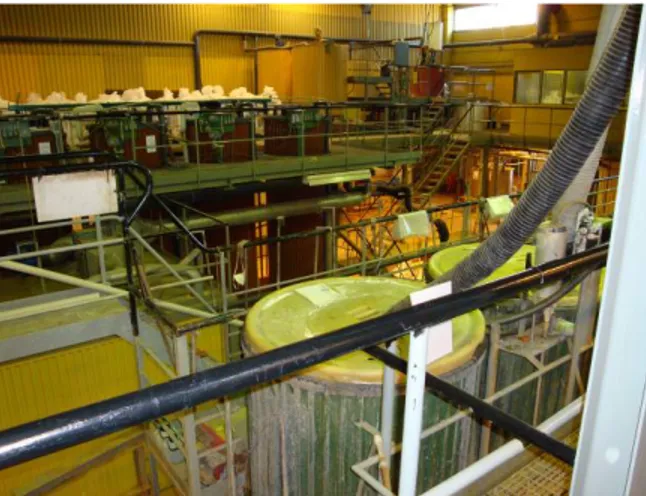
The RMA leaching hall is in a building approximately 46m in length by 24m wide and 15m high, constructed with four floors. It is attached to the large leaching hall. It houses chemical processing equipment on different levels and in several different rooms. Most of this equipment was present and used in the past for the extraction of uranium from the liquor produced in the large leaching hall. Because RMA today processes uranium-bearing wastes, some small additional pieces of equipment have been added in the facility. A selection of photographs of the RMA leaching hall is presented in Figure 2-6 through Figure 2-18.
Figure 2-6 Overview of RMA Leaching Hall Showing Percolation Leach Tanks in Foreground
Figure 2-8 Example of Acid Resistant Tiled Floors
Figure 2-9 Tanks Used in Second Stage of Floculation Process
Figure 2-11 Ammonium Di-Urinate (ADU) Precipitation Tanks (not in use)
Figure 2-12 Liquid-Liquid Extraction in Mixer-Settlers
Figure 2-14 Mid section of Percolation Leaching Vessels
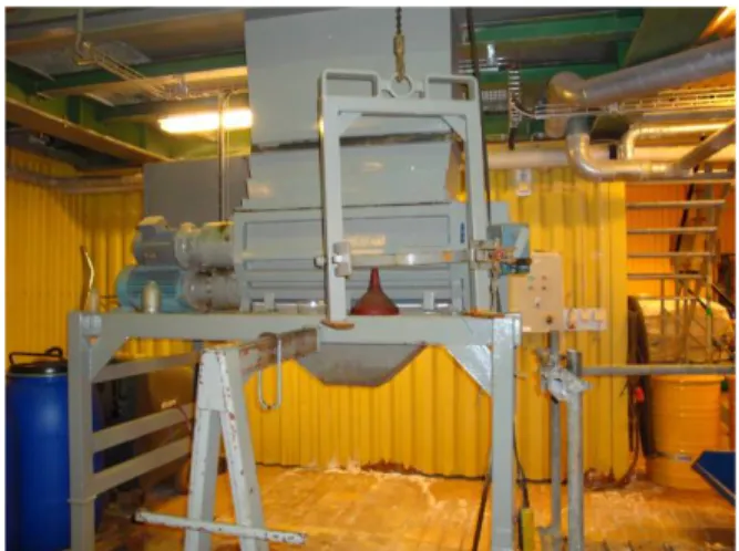
Figure 2-15 Filter Press – Water Cleaning
The selection of photographs shows that the RMA leaching hall includes some relatively clean parts and some parts that have been subjected more to chemical exposure, including acid solutions containing uranium and possibly some other radioactive species. All of the floor areas where acid exposure can occur are made of acid resistant tiles. Drainage systems are in place to receive liquids from the floor areas. This has facilitated periodic cleaning with sulphuric acid in order to reduce the levels of residual radioactive
contamination. What is not known is the extent to which contamination may, or may not, have seeped underneath the tiles and into the concrete. It is entirely conceivable that such seepage may have occurred and may have resulted in significant penetration of the underlying concrete. If so, this would result in larger volumes of concrete that could not be released to public disposal sites. The possible implications of this are considered in more detail in section 3.3.2.
Figure 2-18 Mill for Ashes
2.3
Old Sorting Facility
The old sorting facility is of concrete construction, standing about 91m long by 33m wide and 25 m high. The estimated concrete volume for dismantling/demolition is estimated to be just over 3,500 m3 weighing just over 7,400 tonnes.
Figure 2-20 Magnetite Slurry Pools in Old Sorting Facility
Some of the equipment in the facility has been removed, including crushers and elevators that were part of the sink-and-float system for pre-conditioning the raw alum shales prior to maturing and leaching elsewhere on site. Dust collecting tanks still remain but are more or less empty. Electro-filters that were connected, located outside the building, have been removed already. Some decontamination of the magnetite slurry pools and related pieces of equipment recently were cleaned (decontaminated) by AB SVAFO.
Parts of the building have been segregated and let to other businesses. The former acid preparation area is now used for commercial business activities related to recreational marine equipment (e.g. boat refurbishment). Another area is used for the manufacture of wood pellets. The part of the building that remains unused contains some relatively massive concrete structures, as seen in Figure 2-21.
Figure 2-21 View Showing Substantial Concrete Structures of the Old Sorting Facility Building
Figure 2-23 Dust Collecting Tanks in Old Sorting Facility
2.4
Control Building
The control building is of simple brick construction above ground, containing several rooms including the control room, where most of the original control console equipment remains in place.
Below ground level there are several rooms of concrete construction variously housing pipework, pumps, motors, valves, electrical equipment and suchlike. At the lowest level, pools containing water remain. The decommissioning plan foresees dewatering and then backfilling of the pools and the basement area up to a level of 2.5m below ground level, using waste from the demolition of buildings on the site.
Figure 2-25 One of the Basement Rooms in Control Building
2.5
Lime Silos
Calcium Carbonate recovered in the pre-processing carried out at the sorting facility was stored in six concrete silos located near to the control building (see Figure 2-24).
Figure 2-27 View of Concrete Lime Silos
Based on available information, it is likely that the silo structure is non-radioactive. If so, the decommissioning exercise for the silos should consist of conventional demolition only, perhaps with some segregation of materials (e.g. to separate steel from concrete) afterwards and much of the resulting materials would be candidates for free release. However, in order to confirm the assumed status of this facility, some radioactive mapping would be recommended.
2.6
Heating Plant Building
The disused heating plant (see Figure 2-28 and Figure 2-29) substantially has had the original equipment removed. What remains is a concrete structure clad with corrugated iron sheeting. The decommissioning task related to this building appears to be one of
Figure 2-28 External View on Disused heating Plant Building
Figure 2-29 Internal View of Disused Heating Plant Building
2.7
Transformer Building
The only other building for inclusion in the decommissioning estimate is one that previously housed transformer equipment. The equipment has been removed already but the relatively small buildings, shown in remain for conventional demolition.
Figure 2-30 Transformer Building
The RIC site has many roads that connect the various facilities. For the moment the cost of removing these roads has been excluded form the decommissioning cost estimate. NAC has been advised that, depending on the composition of the roads, removal could be very expensive. The issue concerns environmental regulations which, for certain types of road structure, would result in high costs in order for the management of all of the recovered material to be compliant with the regulations. This is an area of uncertainty that needs to be investigated.
3.
Decommissioning Plan Information
3.1
Decommissioning Scope
In the decommissioning cost estimate the following facilities were assumed to require nothing other than conventional equipment removal and demolition:
Control building Heating plant building Lime Silos
Transformer buildings
All therefore represent candidate sources of material for free release after demolition. In order to satisfy the safety and licensing authorities that this would be possible, it is likely that some monitoring be undertaken, to demonstrate that the presence of radioactive contamination, if any at all, is below the criteria for free release.
The RMA Leaching hall, the Large Leaching hall and the Sorting Facility are assumed to have radioactive contamination and will require a more involved approach, including the following principal elements:
Coarse mapping for possible uranium contamination, as a guide to where concrete surfaces may need to be removed, or for the occurrence of other dangerous substances Physical dismantling of permanently installed equipment, with decontamination to the
extent possible to facilitate declassification
Decontamination of building structures to the extent needed using a variety of techniques Treatment of contaminated concrete in the RMA leaching hall to facilitate subsequent
free release for a larger quantity overall
Final radiological survey to facilitate declassification of the buildings prior to demolition In the case of the RMA leaching hall, the decommissioning program will maintain those
parts of the process equipment needed for treatment of other decommissioning wastes for as long as possible.
Restoration of ground to a natural state of soil that will be seeded to create a true green field condition.
contribute to the decontamination and dismantling effort, is something that needs to be taken in to account when considering the allocation of D&D costs to the various stakeholders.
3.2
Decommissioning Methods/Approach
The approach to be adopted, in logistical terms appears to be sound. To the extent possible, uncontaminated or lightly contaminated equipment will be dismantled first, to avoid, or minimise the spread of contamination onto subsequent items for dismantling. The dismantling techniques available will be selected according to the environment and the condition of the item to be dismantled. To the extent possible, relatively clean techniques (minimising spread of contamination) will be used if there is an assessed risk. More time efficient methods will be used where this is not a concern.
The specific decontamination and dismantling techniques mentioned in the cost estimate report appear to be appropriate to the nature of the facilities to be decommissioned. The availability of the RMA leaching hall provides an added benefit of being able to provide a second possibility for decontamination, which should help to minimise the amounts of waste that cannot be used for backfill and/or disposed of at conventional waste sites.
3.3
Decommissioning Cost Estimate
3.3.1
Cost Breakdown by Activity
The cost estimate for RIC and RMA decommissioning may be broken down into different categories of activity, approximately as shown in Table 3-1. The allocation of each line item to a broad category of activity is based on best judgement about the nature of the activity described. Where costs are related to more than one activity e.g.
decontamination and dismantling, for the purposes of Table 3-1 the cost has been split 50:50 between the two activities. This is an approximation only.
Table 3-1 Approximate Breakdown of Cost Estimate by Category of Decommissioning Activity
Activity Cost including 20% Contingency (MSEK)
% of Total Cost
Remarks
Preparation and Institutional 23.2 12.3 -
Characterisation 5.6 3.0 Initial coarse mapping at about 50 percent level
Decontamination a) 15.7 8.3 Includes decontamination of equipment in operational position as well as processing of some materials after removal from initial location e.g. concrete surface removed
Equipment Dismantling a) 6.0 3.2 Mainly in RMA leaching hall Support to Actual
Decontamination and Dismantling Operations
9.7 5.1 Support across various activities
Conventional Building Demolition
70.7 37.3 May include some dismantling of non-contaminated equipment
Waste Disposal a) 24.7 13.0 According to standard charges in Sweden
Final Clearance 33.8 17.8 Includes final detailed monitoring for declassification purpose
Totals 189.4 100
a) The costs associated with these scopes of work are the principal ones where the rationale for the allocation of costs needs to be analysed carefully.
3.3.2
Principal Uncertainties
Based on the cost breakdown presented in Table 3-1, it is clear to see that for approximately 50 percent of the overall decommissioning cost – associated with conventional demolition and with waste transport and disposal charges in Sweden – it should be possible to achieve a relatively accurate estimate. As long as the volumes of material for demolition and disposal can be estimated with reasonable accuracy, the cost of the related activities should be estimated with relatively good accuracy.
Concerning preparatory work, including radiological mapping, planning and related institutional activity, there should be sufficient experience to be able to assess the necessary resources needed with reasonable accuracy also.
Accepting these two assertions leads to the conclusion that, for about 60 percent of the costs, it should be possible to develop an estimate with which the associated uncertainty will be moderate. Whether or not the actual estimate developed by SKB has achieved this is another question however and needs to be tested; see below.
Decontamination work, dismantling work and the support work related to these activities are the main areas where it is most difficult to achieve good accuracy. One way to enhance the chance of good accuracy is to do a good job of characterising the facility in advance. In the case of the facilities at RIC, based on a site inspection and the available written information, it appears that the main uncertainties correspond to the radioactive condition of the Large Leaching hall and the RMA Leaching Hall.
To some extent the conditions are known, as a result of periodic monitoring of the facilities. Periodic cleaning in the RMA leaching facility also has contributed to controlling the general level of radioactive contamination. However, due to the
construction of the building, with concrete floors covered in acid resistant tiles, and the aggressive nature of some of the chemicals used in the facility, there has to be a
significant risk that the tiled areas are not 100 percent sealed and that areas of substantial contamination therefore will be found underneath them.
With uranium being the principal element of concern, this should not be too big a problem radiologically. In terms of segregating contaminated from uncontaminated material, to facilitate free release to public disposal for much of the waste (rather than sentencing to a radioactive waste repository), the task may be significantly different depending on what is found as the job proceeds. This in turn could affect the relative amounts of waste to be disposed of to free release and to radioactive material repositories, or alternatively it could translate into an extra RMA processing cost to remove uranium. These considerations suggest that the scope of characterisation work may need to be revised, to include more thorough checks in advance, especially in the RMA leaching Hall.
The area of tiled flooring in the RMA Leaching Hall building is quite extensive and available documentation indicates a total area of 1,615 m2. In the available
documentation the area of concrete and tiles assumed to be contaminated by uranium is shown as 50 percent of the gross area, or 808 m2, generating material for disposal with an estimated volume of 8.1 m3 (based on a contaminated depth of 1 cm) and a weight of 19.4 MT.
How much of this, if any, is included in the cost estimate for disposal at the SFL repository is unclear, because the relevant quantities are combined with other sources of waste. It appears that 50 percent of the material (9.7 MT) is expected to be processed in the RMA facilities to remove the uranium contamination and thereby avoid the need for disposal in a repository. It is not clear if some or all of the other 9.7 MT would require disposal at SFL. Either way, if the estimate of the basic quantity of contaminated concrete and tiles within RMA is incorrect, it could translate into either an extra processing and clearance cost and/or an extra disposal cost.
The RMA processing cost for 9.7 MT of concrete and tiles is shown as 289 kSEK, so even if this were to increase 10-fold, it would not make a major difference to the overall estimate; approximately 3 MSEK or 1.6 percent of the total decommissioning cost estimate. The disposal cost at SFL is quoted as 100 kSEK per m3. If instead of an extra processing cost the volume for disposal were to increase 10-fold (i.e. approximately 40 m3, which probably is an extreme assumption), the extra cost would be similar at something like 4 MSEK. Although relatively modest, it may be prudent obtain better information on the extent of concrete and tile contamination in the RMA facility and, in the mean time, to recognised this uncertainty and to include an appropriate contingency amount in the cost estimate.
Also it would be helpful to find an example of a similar uranium processing facility that already has been decommissioned, or has experienced a significant decontamination and/or refurbishment exercise, to benefit from the experience of what was found
compared with what was planned. Such a comparison is outside the scope of what can be included in this preliminary analysis.
how radioactive contamination builds up over time and whether or not it may reach an equilibrium level after some time, irrespective of ongoing operations. This could be important to the consideration of cost allocations, especially in regard to the costs for decommissioning the RMA leaching hall facilities.
A detailed review of all the underlying data supporting the cost estimate is outside the scope of this study. However, based on information gathered during the July 2008 site visit, it is noted that there is some uncertainty regarding the condition of some parts of some plants and such uncertainty seems to have been accounted for by adding a
contingency of 20 percent across all line items. Some refinement of this approach would be desirable, focusing more on the parts of the decommissioning scope that have most uncertainty, to quantify impact on the overall cost estimate.
4.
Comparisons with Relevant External
Benchmarking Results
4.1
Planning and Institutional
The analysis of planning and institutional costs is far from an exact science. NAC has reviewed decommissioning project cost estimates for other older Swedish facilities2, each of which also has been compared with similar projects where actual decommissioning has taken place. The general conclusion is that a large part of the planning and institutional costs may be fixed, irrespective of the total cost of the project. Intuitively it would be expected that some variable costs are involved related to the scale of the project but not necessarily to physical size only, possibly also to complexity of the tasks involved. For the above mentioned Studsvik facilities analysed earlier by NAC, the planning and institutional costs fall in a range of about 6 to 8 MSEK for decommissioning projects, where the total decommissioning project cost was in a range from about 20 to 75 MSEK and the actual decommissioning work, excluding planning and institutional support, was estimated to cost in the range from about 10 to 65 MSEK, in all cases for a single facility. The ratio of planning and institutional cost therefore was in a range from about 10 to 35 percent.
The Ranstad estimate includes about 23 MSEK for a total project cost of 189 MSEK. This however corresponds to the decommissioning of three facilities where radioactive contamination is present and three other significant facilities, plus some minor works, where the task is expected to be more or less only conventional demolition. The
conventional demolition costs for all facilities represents about 70 MSEK of which about 25 to 30 MSEK corresponds to the non-contaminated facilities and the balance mainly for two very large structures – the large Leaching Hall and the Old Sorting Plant. For the Studsvik benchmarks mentioned, final demolition was not a major part of the projects. In order to provide a better basis for comparison, it therefore may be helpful and appropriate
2 Including: SKI Report 2006:31 – An Applied Study on the Decontamination and Decommissioning of Hot
Cell Facilities in the Untied States and Comparison with the Studsvik Facility for Solid and Liquid Waste; SKI Report 2005:34 – An Applied Study on the Decontamination and Decommissioning of the Map Tube Facility 317 Area Argonne National Laboratory, Chicago; SKI Report 2004:13 – A Review of the
to take out the demolition costs from the Ranstad estimate and then consider the planning and institutional costs in ratio to the residual cost.
Taking 70 MSEK out of the 189 MSEK total cost leaves about 120 MSEK, of which about 20 MSEK is for the planning and preparation supporting the decommissioning of essentially three main radioactive facilities. In absolute terms this is about 2.5 to 3 times the estimated planning and institutional cost for individual facilities in Studsvik. Relative to the residual total cost of 120 MSEK, it represents about 16 percent, which is well within the range found for Studsvik facility cost estimates.
In the absence of any more detailed investigation and analysis, this would appear to suggest that the SKB estimate for planning and institutional costs at Ranstad is of the right order. A cautionary observation is that, with such a large project, some surprises might occur during implementation and this could require additional planning effort and/or additional approvals from the authorities.
4.2
Radioactive Characterisation
The Ranstad estimate includes only 5.6 MSEK for characterisation work, including a contingency of 20 percent. This includes radioactive mapping in advance of
decontamination and dismantling but excludes final detailed monitoring to declassify materials so that they can be sentenced to free release.
The estimate includes about 34 MSEK associated with decalssification of building surfaces, ISOCS (In-Situ Object Counting System) measurements on wastes, as well as activities described in the cost estimate as “other inspection and follow-up”. The meaning of the latter is not specified but is thought to correspond to measurements post
decontamination and dismantling rather than being part of the pre-characterisation of the facilities.
Benchmarks for characterisation work are not readily available. Each project tends to have its own fundamental characteristics in terms of design and accessibility, operational history and associated uncertainties, and so on. In addition, for the Ranstad facilities there is a question of scale. Some of the building are very large indeed, so even if they are not necessarily too complex, they simply will demand a lot of effort to cover the large areas involved.
For building surface characterisation, the resources allowance appears to be about 0.6 manhours per m2 surveyed, plus costs for equipment. Intuitively this labour estimate seems reasonable as an average. The commentary in the cost estimate report refers to a basic 20 minutes per m2 surveyed and this is translated into a nominal 1 manhour per m2, including associated activities.
The final declassification effort is estimated to be about six times higher but this relates to the monitoring of a combination of building surfaces, as well as monitoring large volumes of waste. Surface monitoring is understood to involve more than 17,000 m2 but effectively increased to about 26,000 m2 because there will first be a coarse monitoring of about 50 percent of the surface area. Using the above references of 0.6 to 1.0 manhours per m2, this would cost about 8.5 to 14 MSEK (estimate appears to include 11.4 MSEK including contingency). This implies that the balance of about 20 to 25 MSEK would be needed for monitoring of waste volumes and other miscellaneous checks. The total amount of waste assumed to be monitored is unclear. It could be as little as 200 to 250 MT, in which case the implied unit cost for declassification would be approximately 100 SEK per kg. This cost would be divided between labour and equipment costs. This preliminary analysis clearly is subject to large uncertainty. Further checking and analysis would be required in order to be able provide a judgment on the validity of the derived figure and its reasonableness.
4.3
Decontamination
NAC over many years has gathered and analysed a range of data on decontamination resources needed for several different actual and planned decommissioning projects. These analyses indicate very clearly that the resources needed are strongly correlated to the general level of radiation and contamination. This dictates the method of working (remote or man access) the level of protection needed for the workers (with impact on productivity) and the methods to be employed. The wide range of environments to be decontaminated at Ranstad therefore does not lead naturally to a simple comparison. In reference 2, NAC developed curves describing the relationship between dose rate and man hour resources needed in decontamination. The conclusion was that for low dose rates, the labour resources amount to no more than a few hours per m2 decontaminated –
available from the cost estimate, NAC would expect the effort needed in the Old Sorting Facility to be at the low end of the scale and the RMA Leaching Hall at the high end of the scale, with the Large Leaching Hall perhaps in between.
The total in the cost estimate for decontamination, excluding final declassification clearance measurements, is about 15.7 MSEK. This is broken down approximately as shown in Table 4-1.
Table 4-1 Breakdown of Estimated Decontamination Costs
Activity Cost excluding 20% Contingency (MSEK)
Cost including 20% Contingency (MSEK)
Miscellaneous decontamination of equipment 3.9 4.7 Equipment for building surfaces removal (milling) 1.0 1.2 Milling of building surfaces 2.7 3.2 Treatment of milled concrete in RMA leaching hall to
remove radioactivity
1.7 2.0
Equipment for decontamination of components (assumed mainly in the RMA Leaching Hall)
2.8 3.4
Process equipment decontamination in RMA Leaching Hall
1.0 1.2
Totals 13.1 15.7
The available information indicates that about 9,200 m2 of the total building surface area will be milled to remove surface contamination, implying that no more than about 8,100 m2 will require other surface cleaning and the actual figure could be less. At the assumed rate of 542 SEK per man hour for regular labour, the milling of building surfaces cost (2.7 MSEK) would equate to about 0.5 manhours per m2. This appears to be reasonable. This unit cost example is based on information that may be incomplete and/or incorrectly interpreted. As such it must be considered to have large uncertainty associated with it. Surface decontamination in the RMA Leaching Hall may represent more of a challenge than the other major buildings. What is included in the cost estimate for this is not easily visible, so a judgment on this cannot be made without further detailed investigations.
4.4
Equipment Dismantling
The SKB cost estimate includes a range of factors for the weight of equipment that can be decontaminated and dismantled per manhour expended, from about 23 kg per manhour to
Earlier decommissioning cost analyses conducted by NAC have derived unit cost in the region of about 35 to 100 manhours per tonne. The estimated total cost in the SKB work appears to be about 6.1 MSEK but the weight of material to associate with that is not clear. RMA has 159 MT of process equipment (104 contaminated with uranium) plus 9.3 tonnes of ventilation equipment. Taking the total of 168 tonnes and adding 20 percent to cover equipment elsewhere (apparently the assumption used in developing the estimate), the derived unit cost for decontamination and dismantling of equipment would be about 55 manhours per tonne.
These derived figures suggest that the Ranstad estimate is approximately in the correct range but could be low.
5.
Preliminary Opinion on
Reasonableness of the Cost Estimate
The defined scope for this study required a preliminary overview of the Ranstaddecommissioning project. Accordingly the conclusions to be drawn about the overall reasonableness of the Ranstad cost estimate necessarily can only be qualitative and approximately quantitative.
Preliminary analyses suggest that the estimate might be low concerning: Decontamination
Dismantling
Planning and Institutional Work
The estimate for characterisation effort appears to be reasonable but could be subject to an increase if any surprises are found during the decommissioning implementation. The costs associated with declassification activities warrant further analysis, to determine if they are reasonable.
The labour rates assumed in the cost estimate appear to be approximately in line with those used by AB SVAFO in earlier decommissioning cost estimate exercises. They may be higher than the costs of employment for current workers at RMA but the
decommissioning plan apparently foresees the use of external contractors for the most part, so market rates for labour (fully loaded with overheads) will be the applicable values to use.
The conventional demolition expenses included in the cost estimate are based on
indicative costs provided by a contractor working in this field (SKANSKA), delivered in a report to SKI registered on 23 November 2004 with reference (diarienummer) 2004/62. It appears that this 2004 figure (escalated to 2008 for the cost estimate) was not obtained under competitive bidding conditions and no final negotiated price was actually agreed. It’s validity should be questioned. Competitive bidding conditions potentially could result in a lower cost but the recent high inflation, experienced worldwide, concerning energy and commodities and labour costs, may tend to counteract this somewhat. It
The logistics of the decommissioning exercise are somewhat buried in the detail of the estimate. NAC has enquired whether or not the assumptions on worker productivity and total resources needed have been estimated realistically, taking account of real calendar time needed, not just nominal manhours. The issue is one of maintaining teams of workers and recognising that sometimes the program may be held-up in one area but it would be impractical (or contractually impossible) to dismiss the workers temporarily not engaged on the project in an active way. NAC has been advised that there is an
assumption that external contractors will be able to manage this flow of workers so as to minimise down time that has to be paid for. NAC has no specific evidence to determine if the assumptions made are reasonable or not. It is recommended that this should be investigated in more detail.
References
1. Calculation of costs for decommissioning and demolishing certain buildings and facilities belonging to Ranstad Industriecentrum AB, prepared by SKB International Consultants, June 2008
2. An Applied Study on the Decontamination and Decommissioning of Building 200 Hot Cells and Comparison with the Studsvik HCL Facility, Prepared for SKI by NAC International, November 2007