Research
Evaluation of Results from an In-pile Creep
Test in the Studsvik R2 Reactor
Kjell Pettersson
January 2002
ISSN 1104–1374 ISRN SKI-R-02/48-SE
Research
Evaluation of Results from an In-pile Creep
Test in the Studsvik R2 Reactor
Kjell Pettersson
Entropy Materials
S-114 59 Stockholm
January 2002
SKI Project Number 99076
This report concerns a study which has been conducted for the Swedish Nuclear Power Inspectorate (SKI). The conclusions and viewpoints presented in the report are those of the author/authors and do not necessarily coincide with those of the SKI.
Evaluation of results from an in-pile creep test in the Studsvik R2 reactor Kjell Pettersson, Entropy Materials
SKI project 14.6–990513:99076
Summary
An in-pile creep test with bowing of cladding tubes has been performed in a hot water loop in the Studsvik R2 reactor . One test was performed in the core and one outside the core. The out-of-pile sample showed some minor primary creep strain while the in-pile specimen deformed at a steady rate of 5·10-7 h-1. However, when the results were compared to a broader data base
of Zircaloy in-pile creep it became clear that the creep deformation observed is a primary creep which occurs before the irradiation creep in Zircaloy reaches a constant steady state creep rate. This primary stage is interpreted as a consequence of the development of an irriadiation induced microstructure in Zircaloy which does not reach a steady state until a dose of about 1021
n/cm2. At this stage the steady state irradiation creep starts. From this
interpretation it is concluded that it is quite feasible to use the test method on pre-irradiated material in which it can be expected that the steady state will be reached already after short irradiation times.
Utvärdering av ett in-pile krypprov med ledrör i Studsviks R2 reaktor. Kjell Pettersson, Entropy Materials
SKI project 14.6–990513:99076
Sammanfattnig
Ett krypexperiment där kapslingsrörsprover belastats i böjning har utförts i Studsviks R2-reaktor. Ett prov låg utanför härden och ett inuti härden. Provet utanför härden uppvisade bara en mindre primärkrypdeformation medan provet i härden föreföll deformeras med en konstant kryphastighet av 5·10-7 h-1. Emellertid visade det sig när resulataten jämfördes med en mer
omfattande databas för in-pilekrypning hos Zircaloy att observerad krypdeformation var en form av primärkrypning som äger rum innan konstant kryphastighet uppnås vid bestrålningskrypning. Detta primärskede tolkas som ett resultat av uppbyggnaden av en bestrålningsinducerad
mikrostruktur i Zircaloy, vilken inte uppnår ett stationärt värde förrän efter en stråldos av ca 1021 n/cm2. När detta uppnås startas också krypning med
konstant hastighet. Utifrån denna tolkning kan man dra slutsatsen att det är fullt möjligt att använda provningsmetoden på förbestrålade rör i vilka man kan förvänta att den stationära krypningen börjar redan efter kort tid.
1. Introduction
Recent observations of bowing fuel bundles in PWR:s, presumably caused by excessive compressive forces on the bundles, have focused interest on the irradiation creep of zirconium alloys and particularly on the irradiation creep of Zircaloy in the fully
recrystallized condition. In a recent review [1]the following questions were identified as necessary to resolve in order to understand and model the bundle bowing phenomenon:
• What is the influence of Sn content on irradiation creep?
• Is there an acceleration of the irradiation creep of recrystallized Zircaloy in connection with the irradiation-induced microstructural development which leads to an acceleration of growth?
• What are the irradiation creep properties of new cladding alloys at high neutron fluences.
In the review was also discussed possible test methods for the study of irradiation creep of zirconium alloy cladding material. It was concluded that the most suitable method would be to study the tubes under bowing deformation. It should be noted, that the choice of bowing is not made primarily because it simulates fuel bundle bowing, but because it leads to macroscopically large deformations of the specimens for very small creep strains. This is quite important because in that way it is possible to take an irradiated cladding tube and irradiate it for a short time and determine the steady state creep rate typical of its current microstructural state. This would normally not be feasible with for instance a pressurized tube creep test. At a strain rate of 10-7 h-1 the strain obtained in 400 hours
would be 4·10-4 or about 4 µm for a typical cladding tube. Even if this is measurable there
is a possibility that some of the measured diameter change would be due to corrosion or deposition of corrosion products.
When a bowing type of deformation is used in a creep test there is a possibility that the initial linear stress distribution over the specimen cross section is distorted. However in the case of irradiation creep the creep rate normally depends linearly on stress [2] and the stress distribution remains linear. In the review it was suggested that the bowed specimen would be tested under axial compression. However the detailed design work at Studsvik showed that it would be easier to implement a test in which the specimen is subjected to a constant bending moment. A test rig based on that principle was built. The detailed design
of the rig is described in the appendices of reference [3]. That report also contains the results of the measurements done during testing in the R2 reactor. The purpose of the present report is to review the results in the context of previous knowledge on irradiation creep of zirconium alloys.
2. Test Conditions
Two Zircaloy-4 tubes were tested for three irradiation test cycles in a hot water loop in the R2 test reactor. One of the tubes, K1, was tested out-of-flux while the other, K2, was tested inside the reactor core. The test temperature was 317±1 °C. The material was fully recrystallized Zircaloy-4. The tubes had OD/ID 12.40/11.38 mm and a length of 400 mm. The radius of curvature was inferred from measurements of the deflection of the tubes under load. The load during measurement was different from the load during the test because of the temperature dependence of the force for the spring used for applying the bending moment on the specimens. The load gives an elastic deflection on the specimens which is the same during each measurement. Thus the difference in spring force is of no concern for the interpretation of the results since the deflection determined before testing can be deducted from the subsequently measured deflections. The deflections were measured at several points along the specimen and the radius of curvature was determined by several possible methods. These methods gave essentially the same results [3].
3. Results
The results of the deflection measurements are summarized in Table 1. The creep deformation in the outer fibre may be determined from the strain in the outer fibre of the tube which is given by
ε = OD
2R (1)
where OD is the outer diameter of the tube and R the measured radius. The creep strain is determined by subtracting the elastic (initial) strain from the actual strain. The creep strains are summarized in Table 2.
Table 1.
Measured deflections and curvatures at different fluences.
Max deflection Radius of curvature Fast neutron fluence Period length Elapsed time (µm) (mm) n/cm2§ (hours (hours K1-0 2600 7200 0 0 0 K1-1 3000 6300 0 445 445 K1-2 3100 6130 0 442 887 K1-3 3100 6100 0 408 1295 K2-0 2600 7400 0 0 0 K2-1 3650 5140 1.05·1020 445 445 K2-3 4600 4100 1.03·1020 442 887 K2-4 5200 3660 1.16·1020 408 1295
In table 2 a column denoted "Iradiation creep strain" has been inserted. This is the difference between the creep strain in specimen K2 and the creep strain in specimen K1.
Table 2.
Calculated creep strains at different fluences.
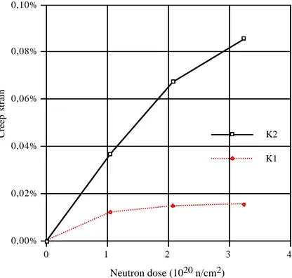
Total strain Creep strain Irr. creep strain Fast neutron fluence Total neutron föuence (%) (%) (%) n/cm2§ n/cm2 K1-0 0,086 0,000 - 0 0 K1-1 0,098 0,012 - 0 0 K1-2 0,101 0,015 - 0 0 K1-3 0,102 0,016 - 0 0 K2-0 0,084 0,000 - 0 0 K2-1 0,121 0,037 0.025 1.05·1020 1.05·1020 K2-3 0,151 0,067 0.052 1.03·1020 2.08·1020 K2-4 0,169 0,086 0.070 1.16·1020 3.24·1020 § E > 1 MeV. Accuracy ± 10 %
The creep strains as a function of fluence (or time in the case of K1) have been plotted in Figure 1. 0,00% 0,02% 0,04% 0,06% 0,08% 0,10% Creep strain 0 1 2 3 4 Neutron dose (1020 n/cm2) K1 K2
Figur 1. Creep strain as a function of fluence for the two specimens. Note that for the unirradiated specimen K1 the fluence scale serves as a time scale.
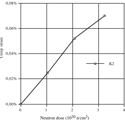
The irradiation creep strain for specimen K2 has been plotted in Figure 2. It gives the impression of a relatively constant irradiation creep rate of 5.7·10-7 h-1.
4. Discussion.
The apparent steady state creep rate seen in Figure 2 is surprisingly high. It may be compared to the compilation of zirconium alloy creep data presented in the previous review [1] which was based on a figure from reference [2]. Figure 3 is reproduced from [1] with the present result included. Note that the present result has been reduced by a factor of 7.23 to account for the higher flux in the R2 reactor compared to the normalized flux of 1013 n/cm2·s in the figure and also to the higher stress compared to the normalized stress of 14000 psi. As can be seen the observed creep rate in R2 is almos a factor of 2 higher than literature data included in the Figure.
0,00% 0,02% 0,04% 0,06% 0,08% Creep strain 0 1 2 3 4 Neutron dose (1020 n/cm2) K2
Figure 2. The excess creep strain in Specimen K2 compared to Specimen K1.
Figure 3. A compilation of zirconiium alloy creep data.
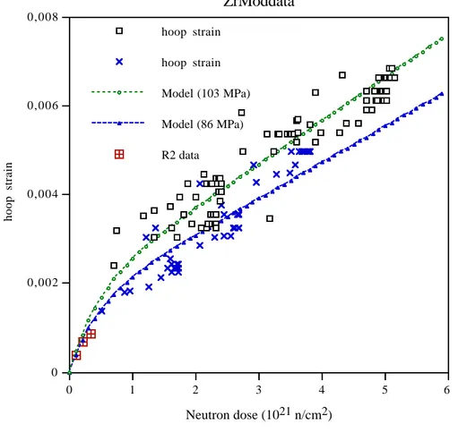
It is interesting to compare the present results with an evaluation of a relatively extensive data base on irradiation creep of cladding tested with external pressure [4]. The present
data points have been plotted together with data from the data base and model predictions for the data of the data base.
0 0,002 0,004 0,006 0,008 hoop strain 0 1 2 3 4 5 6 Neutron dose (1021 n/cm2) ZrModdata R2 data Model (86 MPa) Model (103 MPa) hoop strain hoop strain
Figure 4. Present data compared to model predictions and data from an extensive data base on compressive irradiation creep of recrystallized Zircaloy tube. [2, 4]
The figure shows that the present data actually lies below previous data. The reason why the present data appeared to be higher than literature data is that a steady state creep was not reached in the R2 experiment.
The same data set was modelled by Limbäck and Andersson [5]. However the only primary creep included in their model was an independently measured primary creep of thermal origin. It is clear from the present data that there exists a sort of primary stage also for the irradiation creep. In the case of Limbäck and Andersson they could improve the fit to the data base by assuming that the creep rate had a power law dependence of neutron flux with an exponent of 0.85 instead of the normally assumed exponent of 1. As discussed in [1] an exponent less than 1 is not unreasonable but it seems to be a more natural way to assume that the exponent is 1 and add a primary stage to the creep. It
should also be noted that the exponent on flux has an effect on the momentary creep rate. At constant flux the creep strain would still be linearly dependent on fluence.
The best fit to the creep data in Figure 4 follows the equation [4]
˙ ε = Aσφ Φo exp −Φ Φo + Bσφ (2) where A = 2.27·10-5 1/MPa Φο = 4.33·1020 n/cm2 B = 1,256·10-26 cm2/n
The flux φ should be expressed in n/cm2/h and the fluence Φ in n/cm2. It should be noted that in order to obtain the curve in the figure the strain evaluated from eq. 2 should be divided by 1.5 to account for the fact that the effective stresses and strains in a pressurized tube are different from the uniaxial values.
The new short term data seem to confirm that there is a primary creep stage in irradiation creep which does not depend on the thermally induced primary creep. It is interesting to speculate on the origin of this primary creep. On one hand the ongoing irradiation will help the dislocations to pass obstacles which they can not normally pass at the applied stress. On the other hand new irradiation induced obstacles are created until a steady state situation is reached. Thus it is quite natural that the creep rate will decrease with time until the irradiation induced microstructure has reached a steady state. This is when the steady state creep starts. Such a picture is consistent with the dose values when the yield strength increase in irradiated Zircaloy starts to saturate. This is normally around 1021 n/cm2 [6]. The present data is somewhat below the best-fit correlation. However it is quite
conceivable that minor alloy variations can account for the difference. If the assumption that the transient stage depends on the build-up of an irradiation induced microstructure this has some implications for the idea to use this test method on pre-irradiated tubes. Since a pre-irradiated tube already has a fully developed microstructure it can in fact be expected that steady state creep will start fairly soon after start of the creep test. It will probably not start immediately, there will be a short transient stage, when the microstruc-ture is adjusted to the neutron flux used in the creep test, if that is different from the flux
during pre-irradiation. In summary, the test method looks quite promising for its intended use.
5. Conclusions.
° The short term data has confirmed that there is a primary creep stage irradiation creep which is not due to thermal creep.
° The short term creep test for cladding tubes under bowing deformation is promising for determination of steady state creep rates as a function of flux and stress.
6. References.
1. Pettersson, K., Irradiation creep of zirconium alloys at high neutron fluences – an
assessment of the state-of-the-art. 1997, Department of Materials Science and
Engineering, KTH: Stockholm.
2. Franklin, D.G., G.E. Lucas, and A.L. Bement, Creep of Zirconium alloys in
nuclear reactors. ASTM STP 815. 1983, Philadelphia: American Society for
Testing and Materials.
3. Tomani, H. and U. Lindelöw, In-pile creep tests of Zircaloy tubing in Loop No. 1
in the Studsvik R2 reactor. 1999, Studsvik Nuclear.
4. Pettersson, K., High-fluence creep of Zircaloy fuel cladding under irradiation. 1994.
5. Limbäck, M. and T. Andersson. A model for analysis of the effect of final
annealing on the in- and out-of -reactor creep behaviour of Zircaloy cladding. in Zirconium in the Nuclear Industry: Eleventh International Symposium. 1995.
Garmisch.
6. Pettersson, K., G. Vesterlund, and T. Andersson. Effect of irradiation on the
strength, ductility and defect sensitivity of fully recrystallized Zircaloy tube. in Zirconium in the Nuclear Industry (Fourth Conference). 1979.