Proceedings of the 2011 IEEE International Conference on Mechatronics
April 13-15, 2011, Istanbul, Turkey
Kinematics and Dynamics of a novel
6-DoF TAU Haptic Device
Aftab Ahmad#l, Suleman Khan*2, Kjell Anderson#3
# K TH, Royal Institute of Technology, School of Industrial Engineering and Management Department of Machine Design, SE-10044, Stockholm, Sweden
'aftaba@kth. se 2sulemank@kth.se
3kan@kth. se
Abstract-This paper presents the kinematics and dynamics modeling of a novel hybrid kinematic concept, i.e. the TAU haptic device. This new concept was obtained from the modification of TAU-2 structure proposed by Khan et al (I]. First a kinematic model for inverse and forward kinematics was developed and analyzed. Then an algorithm to solve the close form inverse dynamics is presented using Lagrangian formulation. Numerical simulation was carried out to examine the validity of the approach and accuracy of the technique employed. A trigonometric helical trajectory of 5th order spline was developed in Cartesian space for each degree of freedom of the moving platform in order to verify and simulate the inverse dynamics; the motion of the platform is such that the tool centre point remains on this trajectory while its orientation is changing constantly in roll, pitch and yaw.
Keywords-component; Haptic device, Human robot interface, Mathematical Modelling, Simulation and TAU Configuration.
I. INTRODUCTION
Research on haptics focuses on the assistive technology, which create a physical interface between human's sense of touch and computer generated virtual world, or remote environment. Based on manipulation and interaction with objects within the virtual or remote world, these devices provide feedback forces and torques to the user. Research on haptic devices is getting high attention of researchers due to their emergent applications in many fields like medicine, tele robotics, engineering design, and entertainment [1]. Due to the wide area of application of these devices, the application environment put conflicting design requirements e.g. large workspace, high stiffness, low inertia and compactness on this device. Commercially as well as in research labs currently both serial and parallel mechanism based devices are used for above specified applications [2]. However, these mechanisms have some advantages as well as some drawbacks. Therefore, we have started to develop a new mechanism, called 6-DoF TAU haptic device [2]. The idea behind this development was to obtain sufficient stiffness, enough workspace and compact design to fulfill the user requirements for the simulation of surgical procedures in hard tissues and bone structure [1]. This hybrid mechanism combines the good characteristics of both parallel and serial mechanisms [3, 4]. Zhenqi Zhu [4] worked on the kinematic analysis and error modeling of new 3-DoF mechanism based on serial-parallel mechanism, called 3- DoF TAU parallel robot. However, there is no effort made to
978-1-61284-985-0/11/$26.00 ©2011 IEEE
develop kinematics of 6-DoF TAU device. Furthermore, different models of 6-DoF TAU structures has been developed and analyzed by Khan et al [1] to identify their best characteristics.
Dynamic motion simulation plays an important role in many engineering application domains where there is in an interaction between user-applied external outside disturbance to the active bodies like in virtual reality, robot motion simulation and haptic devices in tele-operation. These disturbance such as contact, change their dynamic behavior, in other words it changes the course of simulation trajectories by keeping the track of changes in dynamics. When good dynamic performance and precise position are required, the dynamic model is important for their control.
In the last few years the both parallel, serial manipulators have been up to some extent dynamically investigated by many researchers using different approaches like, Newton Euler formulation [5], Lagrangian formulation [6], principle of virtual work [7] and generalized momentum approach [8].
The Lagrange method describes the dynamics of a mechanical system from the concepts of work and energy. This method enables a systematic approach to develop equations of motion of any mechanical system. Nguyen and Pooran [10] use this method to model a Stewart platform, modeling the legs as point masses. Ahmadi, M et al [11] study dynamical modeling of a parallel robot Hexa using Lagrangian equation of the first type. Less effort is made on dynamic modeling of TAU configuration manipulators. Hongliang et al [3] and Zhenqi Zhu et al [4] have developed kinematic and dynamic model of 3 DOF Tau parallel robot.
However, in this research work, first we develop a kinematic model for inverse and forward kinematics. Thereafter we develop a dynamic model of the system, where the desired motion is given in terms of position, velocity and acceleration in Cartesian space and the required actuators torques are calculated. The resulting dynamic model is also very useful for control design process and will be utilized in the future work for the control design and optimization of the device.
The remaining of the paper is organized in sections. Section
II presents the conceptual model and kinematics of the proposed 6-DoF haptic device, section III deals with the inverse dynamics. Furthermore numerical simulations, results and discussion are presented in section IV and V.
II. KINEMATIC MODEL OF TAU HAPTIC DEVICE A. Conceptual model of the proposed haptic device
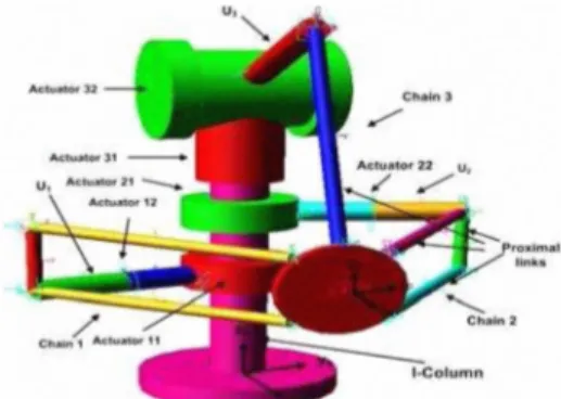
This novel concept of a 6-DoF haptic device is a modified version of the TAU-2 structures proposed by Khan et al [1]. The back and supporting arm was removed from TAU-2 and a universal joint was replaced by a revolute joint to get this concept. This configuration consists of fixed I-column, a moving platform and three parallel chains (1, 2 and 3) which connect the base frame to the moving platform. Chain 1 and chain 2 are symmetrical while chain3 is unsymmetrical as in Fig 1. Each symmetrical chain has two active rotational actuators, one attached to the I-column while another one is mounted on the upper link U\ and U2• Furthermore chain 1 and 2 have two extra proximal links connecting the platform to upper links U\ and U2 to increase the structural stiffness. The third chain, chain 3, has also two active rotational actuators, one attached to the I-column and the other mounted at the top of the device. This concept is an asymmetric serial-parallel configuration that provides 6-DoF motion at moving platform. The advantages of this concept as compared to the TAU-2 are compact structure, large work space, and small actuating torque for unit applied force on the TCP.
Fig. 1. Conceptual model of the new TAU 6-DoF haptic device. B. Kinematic model
The considered kinematic structure is an asymmetric serial parallel (hybrid) configuration where the pose (position and orientation) of the platform is determined by the position of each joint point Ci of the platform. Furthermore the position of each joint point Ci of the platform is the same as the position of the end point of each serial manipulator. Due to this configuration, it is advantageous to the kinematic analysis to consider the serial and parallel structure separately as proposed by S.Lee [12] for serial-parallel manipulator.
To solve the kinematics, the kinematic model was simplified by considering three serial chains AiBiCi
(
i =1, 2, 3) as shown in Fig 2. Furthermore five different coordinate systems were used, i.e. base frame{
N}
, local leg framesNF{N], N2, N3}
and platform frame {Pl. The leg frames for parallel chain 1 and chain 2 are positioned at 1.5d, 3d and 4.5d respectively along z-axis with respect to base frame{N}
according to the preliminary analysis done for the maximum workspace and minimum actuator torques in ADAMS [13], Inthis paper intermediate rotation of frames were used to fmd the coordinates of Ci with respect to leg frame
{Ni}
according to the rotations given in equation 1 for (i = 1, 2) and equation 2 for (i =3).NiTCi
= rot(Z,8il).rot(X,8i2)Jrans(X,Ll)·rot(Z, ¢il).rot(Y,�i2)trans(X,L2) (1)NiTCi
= rot(Z,8il).rot(YA2).trans(X,Ll).rot(Y,¢il)Jrans(X,Lz) (2) Now the joint positions Ci of platform for chain 1, 2 according to equation to (1) are given in (3-5), while for chain3 the joint position Ci according to equation 2 are given in (6-8).plxi = cos Bil (Ll + Lz cos¢il cos¢i2)
-Lz sin Bil (cos Bi2 sin ¢il cos ¢i2 + sin ¢i2 sin Bi2)
plyi = sin Bil(LI + Lz cos¢il cos¢i2)
+ Lz cos �1 (cos Bi2 sin ¢il cos ¢i2 + sin ¢i2 sin Bi2)
plzi = Lz(sin Bi2 sin¢il cos¢i2 - cosBi2 sin¢i2) pi", = COSBil«� + L2coS¢il)COS0,2 -L2sinBi2sin¢il) ply, = sin Bil «� + L2 cos ¢il)COS0,2 -L2 sin 0,2 sin¢il) plzi = -«Ll + Lz cos¢il)sin Bi2 + L2 cosBi2 sin¢il)
(3) (4) (5) (6) (7) (8) Where Wil, Od are orientations of active revolute joint angles while
{
(Pn'¢i
2}
for (i = 1, 2) and{
¢i
l}
for (i =3) are orientation of passive universal and revolute joint respectively.C. Inverse kinematics
The inverse kinematics problem for the proposed 6-DoF TAU configuration determines all orientation Goint angles) [Oil, Oil] of all active actuators while pose fp" Py, pzo n, p, y] of the platform is given. A close form solution for inverse kinematic can be found by using geometric method as shown in Figure 2, and using equations (3-8). The closed-loop vector equation for each chain i= 1, 2 and 3 is given in equation (9).
N
PN
pli = Pd + Rp pUi -
Ni
H (9)Where pli =
[
PI., PI . ,PI. Xl yl]
= [(Px, Py' PZ' a, 13, r) is the poslt1on Zlvector of the junctions point Ci of the platform in local leg frames Ni =
{
Nb N2, N3}
. And vector Pd represents position of moving frame{P}
with respect to the base frame{
N}
,�
H denotes the linear transformation to the local leg frame from the base frame. Where NRp is a rotational matrix based on roll-pitch-yaw(a, �, y)
angles of platform. It defmes the orientation of the moving platform w. r. t the base coordinate{
N}
. The active joint angle for link chainl, 2 and chain 3 are derived by using transformation of coordinates of the junction point Ci from leg coordinate{ Ni }
to intermediate coordinate{ N
il}
using equations (10-12) for (i = 1,2) .plxicosBil + plyiSinBil = L1 + L2cos¢il cos¢i2 (10)
-pixisin8z1 + piyicos8il =L2(cos¢i2sin¢'1 cos 8;2 + sin¢i2 sin 8;2) (11) plzi = Lz(sinll;zsin¢i1 cos¢i2 -cosll;zsin¢i2) (12)
Geometric method is used to fmd the passive angles
¢il'¢i2 for link chain i = 1,2,3 as shown in Fig. 2.
x
Fig. 2. Kinematic model and design parameters.
-1
,?
+ Lf
-�
. -1 plZi 2 2 2 2¢il = cos ( 2LILz ) , ¢i2 = sm (-) where Lz r; = plxi + plyi + plzi
Now 0il(i = 1,2) can be found from equation (10), by
simplifying such that Plxi = al> ply; = q and
al.cosOil + q sin Oil = q (13) Solution of equation (13) will yield two solutions for Oil as shown in equation (14).
(14) Similarly (}i2 can be found from either equation (11) or (12), simplifying equation (12), such that
plzi
= C2, -�sin¢i2 = a2 and �cos¢i2·sin¢il = � Th' . . IS gIvesa2·cos0i2 + �.sin0i2 = C2 (15)
Solution of equation (15) yield two solutions for (}i2
-I �±
�
�2+ a22-c220i2 = 2. tan e ) (16)
a2 + C2
The active joint angles for link chain 3 can be found by squaring and adding equation (6) and (7) and by simplification we will get equation (17).
�
p lx/ + p ly/ � (�+L2 COS ¢i1)cOS 0i2 -L2sinOi2sin¢i1 (17)Simplifying equation (17) such that
�
pl,l
+pl/
= CJ, (4 + � cos ¢i1) = a3 and -1Q sin¢!! = hjSo equation
(
17)
becomes.C3 = a3 cos 0i2 + b:, sin 0i2
(
18)
Solution of equation
(
19)
yields two solutions for (}i2 as shown in equation(
19).D.
-I b5 ±
�
b52 + a52 -C520i2 = 2. tan ( )
(
19)
a5 + C5
Active joint Oil for i=3 can be fmd by using equation (6)
�. Z = cos-Ie
plxi
)(
20)
(LI + � cos ¢il) cos 0i2 -� sin 0i2 sin¢il
Forward kinematics
The forward kinematics determines the pose [P.v PY' Pz, a,
p,
y] of the platform while given the joint angles [(}ib (}d of all active actuators. No closed form analytical solution is available for forward kinematics of 6-DoF TAU configuration, due to the complex non-linear equations. Therefore Newton Raphson numerical approximation method is used to solve this forward kinematics problem. The Newton Raphson approximation to the solution is given by equation
(
21)
.Xn+1 =Xn -[F'(Xn)rl.F(Xn)
(
21)
Where Xn is the initial guess value of platform pose, while Xn+l is the solution that is to be determined through a function F(Xn) and its derivative F'( Xn) . F(Xn) is defmed separately for each serial manipulator and parallel structure by the method proposed by Soo S. Lee [12]. Two different functions were defmed for each serial chain and parallel configuration. For each serial link this function is defmed from the end junction point C; of the chain with platform and the joints angles as F;{X,J=(}i= Fpi(PJ, and its differentiation can be obtained as0i = JsdJi
(
22)
Where for each serial manipulator (}i = [(}i1 (}i2], Pi = [Pxi Pyi pz;] are the coordinate of the junction point Ci in base
coordinates where (i=l, 2, 3), and;'i can be defmed as. <JFpli <JFpli <JFpli
[
J"0
: }
R'" <JPxi <JPyi <JPzi
Jsi = <JFp2i <JFp2i <JFp2i ,Js =
�
Js2 (23)0 Js3
<JPxi <JPyi <JPzi
For the parallel case the function is defmed by the relation between the junction vector of the platform Pi and the generalized coordinates can be expressed as Pi= Fx;{XJ, and it differentiation is obtained as
Pi
= JpiXWhere FxF[Pxi Pyi Pzi], and X = P.v PY' Pz, a,
p,
y. The components of Jacobian matrix Jpi for each junction are calculated on the base of equation(
2)
. The Jacobian for the whole system is derived by putting equation (24) into equation(
22)
as given,. . . 6x6
0i = Jsi.JpiX= JX ,J = Jsi.Jpi E R
(
25)
Now the forward kinematics, using equation(
21)
can be calculated by suppose an initial guess of pose Xn and update its value by M that is calculated from the inverse of the Jacobian matrix and tolerance (error) d(} between the required and calculated joint angle.M = [J(X)]6X6 -I. dO (26)
Xn+1 = Xn + M
(
27)
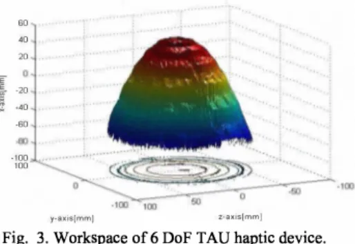
III. WORKSPACE
The approach used in this paper, utilizes a searching technique for locating the workspace boundary on planes parallel to the Y-Z plane at discrete values of X location using constant orientation of the platform. Potential platform locations are determined to be inside or outside the workspace by calculating the inverse kinematics and then testing if each of the joint angles (}a, and (}i2, has real values.
60 40 20 I ! -20 .. -40 -60 -100 100 y-axislmmJ z-axjs[mmJ
Fig. 3. Workspace of 6 DoF TAU haptic device.
IV. INVERSE DYNAMICS
The Lagrange method describes the dynamics of a mechanical system from the concepts of work and energy. The general equation for Lagrange dynamic formulation is
:t
[:� )
-:�
= T(
28)
Where L = K - P , is the Lagrange function, K is total kinetic energy of the system, P is total potential energy of the system, qi is generalized coordinates
[px,py,pz,a,p,yJ,
qi is corresponding velocity of generalized coordinates.A. Kinetic Energy
1) Kinetic Energy of platform
For simplicity the platform is modeled as a point mass at the centre of plate, the kinetic energy of the platform can be written in the form
(29)
[
. . . .J
T[
b b]
T .Where q
=
Px Py pz
a Pr=
vp
,lx
3
liJ p
,lx
3
IS the vector of generalized velocities of platform and Mp
is the mass matrix of the platform .[
mp
xI3x3
03X3
]
M
p
=03X3
b bT ER6X6
RfJ p(Rp)
(30)Where I
p
the platform inertia tensor at the centroid, andR
�
is the rotation matrix of the platform coordinates with respect to the base frame presented.2) Kinetic energy of serial links
Since the 6 DoF TAU haptic device consist of 3 serial link chains as shown in Figure 2, so we need to frod the kinetic energy of each link of the three serial chains. But to simplify the analysis each link is assumed as a rod with mass M and length L and cross-sectional area A, the moment of inertia of the rod can be computed as the limiting case of the moment of inertia of a cylinder such that radius R � 0 .
Sine chain 1 and 2 are symmetrical so kinetic energy of chain 1 will be presented here.The kinematic chain i (i=l, 2) consist of four links AiBi , BiCi , BiDi and DiEi , for serial manipulator the mass of each link exist at a centre point in the form of point mass.
B. Kinetic energy of link AiBi
For serial manipulator the links can be considered as slender rod where mass of each link exist at a centre point in the form of point mass. Position of the centre of mass of link
�Bi can be expressed in the local frame as
Li Li · T
rAiB! =[TCOsOi'TsmOi,O] (31) Linear velocity of the centre of mass can be obtained equation.
v AiBi = (J) AiBi X r AiBi
where
(J) AiBi =[0 0
OiJ
where Bi is related to the generalized velocities through the jacobian matrix given in equation (25). Therefore the kinetic energy of the link can be obtained as
KAiBi =
�
V�
BiM AiBiVAiBi (32)Where V AiBi and M AiBi are the mass matrix and velocity vector respectively as given in equation (33) and (34).
T
vAiBi =
[
vAiBiX vAiBiy vAiBiz wAiBix w AiBiY WAiBiz]
(33)(34)
Where mass moment of inertia of the link AiBi in the fIxed frame.
C. Kinetic energy of link chain BiCi
The kinetic energy of link BiCi can be obtained as using a closed loop equation. Since link BiCi is connected to the moving platform through a spherical joint so the velocity at that point Ci can be obtained though the translation velocity
of platform and relative velocity of point Ci to the platform coordinate system.
(35) Where
vp
=[Px Py pzJ
andliJp =
[eX
jJ
rJ
are the
angular velocity of platform,
Linear velocityVBi
of point Bi can be found from angular velocity of link AiBi ,(36) Where
rBi =
[4
cos 0i4
sin 0i0]
and linear velocity of pointci can be computed from the linear velocity of Bi and angular velocity oflink BiG; •
VCi = VBi + liJBiCi
X BiCi (37)BI I .C=
[
X Cj -'·coso,· � I y Cj -'·sino'· � I z Cj-2d]
i (38) where the coordinates of junction points [XCi
' Y Ci
,zci
] andPCi can be given by equation (1). Equating the above two equations (35) and (37).
liJBiCi
x
BiCi= vp + liJp
X PCi-liJ A,Bi
X AiBi (39) Performing cross product of vector BiCi on both sides of equation (39) from right and using the property of triple cross product,liJBiCi
will be found asliJ'B C
j jx
BI I - C xB·C = I I[v + liJ xBC -liJ A B
P P I I �"i j �""J Ix
A.B.]
XBC (40) I I Since the term(
BiCi.liJBiC
) is equal to zero because link 2 isbetween a universal and spherical joint and is not allowed to have any rotation in the direction of itself, sorting the terms,
OJBiCi
is computed asliJBiCi
=4
.[
BiCiX(
Vp+liJpXBiCi-liJA,BiXAiBi)
]
(41)Using
{J)BiCi
linear velocity of centre of mass of link BiCican be calculated as.
1
VBiCi =liJA,Bi x4Bi +2liJBiCi
X BiCi (42) So the kinetic energy of link 2 can be calculated in the compact form as(43)
Where (44)
RtiCi
is the orientation matrix for link BiCi in a frame attached to link BiCi, the frame attached to link BiCi is chosen as : axis XBiCi
coincides with the link BiCi and points from the fIxed length link to the platform, meaning that it is coincident with vector BiCi, axisYBiCi
is perpendicular to xBiCi
' axisZBiCi
complete the frame following the right-hand rule and its projection along the Pz is always positive, so the rotation matrix becomes.D. Kinetic energy of link chain BiDi
Velocity of link BiDi can be found by using the assumption that the two links RiCi and DiEi are parallel to each other, so there angular velocity will be same.
(46) Velocity of point Ei can be found from the closed loop equation.
VEl
= VB, + aJBp, X RiDi + aJD
,E
, xDiEiVEl
= Vp + aJp X PEiBPi
=
[
XDi
-LlicOS�DE· Z l =
[
XE - xD
i
j
YDi
-LlisinOi z�-ZdJ
Y£, - YD. z£, I I I- ZD.
I]
(47) (48) (49) (50) (51) So linear velocity of the centre of mass of link BiDi is1
VBA =
wA;Bi
xA;Bi +"2WBiD,
X BiDi (52) The kinetic energy of link BiDi can be calculated in the compact form as(53) The orientation matrix
R�iDi
for link BiDi can be found by the same procured the one used for link BiCi .E. Kinetic energy of link chain DiEi
As it is assumed that the two links BiCi and DiEi are parallel to each other, so there angular velocity will be same from equation (41),
aJDE
= aJBe , So velocity of the centre ofI J I J mass of link DiEi can be found as
1
VD,E,
={J)
A,Bi
xA;Bi +{J)BiD,
X BiDi +"'2
{J)DiEi
X DiEi (54) So the kinetic energy of link DiEi can be calculated in the compact form as1 [
T T]
[
VDiEi
]
KDE=-
I I 2 VDjEj DiEj
W
MDE
I I(J)DjEj
(55) The orientation matrixR
�
Pi
for link BiDi can be found by the same procured the one used for link BiCi .3) Kinetic energy of chain 3
The kinematic chain3 consist of two links A3B3 and B3C3 , so the kinetic energy can be calculated by the same procedure the one used for A;Bi and BiCi .
F. Potential Energy of Platform Potential energy of the platform is given by
Up = mpgpz (56)
Where Pz is the z- component of the position vector of the centre of mass of platform expressed in the base coordinates.
G. Potential energy of chain 1
Since the 6 DoF TAU haptic device consist of 3 serial link chains as shown in Figure 2, so we need to fmd the potential energy of each link which is shown in Figure 2. For simplicity only the potential energy of link chain 1 and 3 is given.
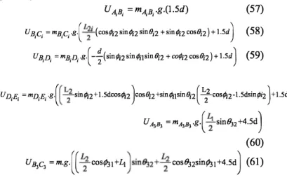
Potential energy of link
AiBi
, BiCi , BiDi , DiEi, A3B3 and B3C3 is given byU A,B, = mA,B,g·(1.5d) (57)
UR,Ci
=mB,c,g{
L�
i (cos¢i2sin¢;zsinOi2 + sin¢;zcosOiZ) + l.5d)
(58)UB.n =mB.n.g.I J I I
(
-�(sin¢;zsin¢;1sinOiZ 2 + co¢;z COSOiZ) + l.5d)
(59)U
D,E,
=mD,E,
.g{ (
L�
sin¢;z + l.5dcos¢;Z}
OSOi2 +sin¢;1sinOiZ(
LZZ cos¢;z -l.5dsin¢iz)
+ l.5d)
UA3B3=
mA3B
3 .g.( ;.
sinB.J2+4.5d)
(60)
UB3C3
=
m.g.( ( ;:
cos¢.l1 +L1}
in8.Jz+;:
cos 8.Jzsin¢.l1 +4.5dJ
(61) H Lagrange equation in Cartesian spaceUsing the Lagrange's equation, the dynamic equation in the Cartesian space can be obtained with the kinetic and potential energy obtained above. Similarly the total kinetic and potential energy can be simplified by adding the kinetic and potential energy of all components and fmally the Lagrange equation will be
M(q)ij + M(q)q + qT M(q)k + G(q) = T
V(q:;l)q
M(q)ij + V(q,q)q + G(q) = TC 1. Lagrange equation in joint space
(62) (63)
In order to derive the joint torques we will use transpose of the inverse of Jacobian matrix as given in equation.
Tj = rT TC (64)
The equation of motion that shows the torques on actuators in joint coordinate system as
M(O)B+V(O,O)+G(O)=TJ (65)
Where 0i = Jqi and Bi = Jiji + jqi
V. NUMERICAL SIMULATION
A numerical example of the inverse dynamic model developed in the previous section has been implemented in MAPLE® and simulated in MATLAB®. The geometric parameters used during simulation is presented in the Table 1.
A trigonometric helical trajectory is developed in Cartesian space and joint space for each degree of freedom for the moving platform in order to verify and simulate the inverse dynamics; the motion of TCP of platform is such that point P remains on this trajectory while its orientation is changing constantly in roll, pitch and yaw.
TABLE I' GEOMETRIC PARAMETERS
Parameters values Parameters values
Ro 45mm mo 0.1 kg
L] 15 0mm mass of L] 0.05 kg L2 200mm mass ofL2 0.05 kg
d] 60mm g 9800 rnm/s2
1) Trajectory in Cartesian space
To generate a simple trajectory in Cartesian space, we let the position vector of point P of TCP be defmed in base frame by a vector-valued function that represents the position vector of a point of a helix, defmed in (66)
x =
Px
+ b(
/3 +w),y
= acos(
/3 +w),y
=Pz
+ asin(
/3+w)
az
= acos(
/3 +w),/3y
= a cos(
/3 +w), Yx
= a cos(
/3 +w)
(66)Where a ,b m and
w
are scalar constants, the ftrst two with units of length, the last two are dimensionless, while /3denotes the parameter of the helix that varies with time t according to the quintic polynomial (67).
5
/3=
L
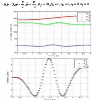
aktk k�O(67) The coefficient of can be found by using initial condition motion of the manipulator starts at t = 0 and at time t = t f . To simulate the trajectory for 6 DoF motion in Cartesian coordinate we choose t = 0 and t = 5 seconds and the
following parameters were assumed. The trajectories are shown in Fig 4.
1( _ 1( R R
a = 6,b = 3,w = -,W =-, I'J = 10,1'0 = O,ao = O,al = 0,a2 = 0
2 10 Time i. sec
i
..r:
..J
....1.
'e> : '" . · . . ; .. 9· .... ...� T,me I. s.e 45Fig.4. Trajectories of pose and orientation and helical trajectory in Cartesian space.
2) Trajectory in joint space
To fmd the trajectories in joint space we to use the inverse kinematic model developed for joint orientation (}i , see Fig 5.
-60 . - .. !.
""0 05 15 25 35 45
Fig. 5. Trajectories of actuators orientation in joint space.
3) Actuator torque in joint space
The resulting actuator torques, given by the inverse dynamic simulation is shown in Fig 6.
VI. CONCLUSIONS
In this paper, the inverse kinematics and inverse dynamics of a novel 6 DoF haptic device based on TAU conftguration is presented in closed form and forward kinematics using Newton Rapson approximation. The study presented in this paper provides a framework for future research such as stiffness, control model and structural optimization design of the 6 DoF TAU haptic device.
llmes9C
Fig. 6. Trajectories for on actuator torque.
To study the motion characteristics we introduce a kinematic model that was used to derive the dynamic equation of the system based on lagrangian dynamics. In the kinematic analysis the inverse kinematics has been performed using homogeneous transformation. Particularly, all component equations needed for dynamic analysis have been derived in closed form. A graphic user interface (GUI) was developed for inverse and forward kinematics in Matlab to verify the validly of the mathematical model as shown in Fig 7.
... - .. -"'�-... --:: ... ,-;" ... -;;;
... � __ �u...,_
Fig 7. Gill of 6 DoF haptic device REFERENCES
[1] Khan, S., Andersson, K., and Jan Wikander, "A Design Approach for a new 6-DoF Haptic Device Based on Parallel Kinematics", presented at IEEE International Conference on Mechatronics, ICM [2] [3] [4] [5] [6] [7] [8] [9] [10] [11] [12] [13] 2009 Spain.
Aftab. A. Kinematic and Dynamic Modeling of 6-DoF TAU Haptic Device, Master of Science Thesis, Department of Machine Design, KTH, Royal Institute of Technology 2009.
Hongliang cui, Zhenqi Zhu, Zhongxue Gan, Torgny Brogardh. "Kinematics analysis and error modeling of TAU parallel robot". Zhenqi Zhu, Jinsong Li, Zhongxue Gan, Hui Zhang. "Kinematic analysis and error modeling of TAU parallel robot for real -time control of Tau parallel robot".
Dasgupta, B. and Mruthyunjaya, T., "A Newton-Euler formulation for the inverse dynamics of the Stewart platform manipulator," Mech. Mach. Theory 34, 711-725 (1998).
Abdellatif, H. and Heimann, B., "Computational efficient inverse dynamics of 6-DOF fully parallel manipulators by using the Lagrangian formalism," Mech. Mach. Theory 44, 192-207 (2009). Tsai, L.-W., "Solving the inverse dynamics of Stewart-Gough manipulator by the principle of virtual work," J. Mech. Des. 122, 3-9 (2000).
Lopes, A. M. and Almeida, F., "The generalized momentum approach to the dynamic modeling of a 6-dof parallel manipulator," Multibody Syst. Dyn. 21, 123-146 (2009).
Dasgupta, B., Choudhury, P.: A general strategy based on the Newton-Euler approach for the dynamic formulation of parallel manipulators. Mech. Mach. Theory 34, 801-824 (1999).
Nguyen, c., Pooran, F. "Dynamic analysis of a 6 DOF CKCM robot end-effector for dual-arm telerobot systems". Robot. Auton. Syst. 5, 377-394 (1989).
Ahmadi, M. Dehghani, M. Eghtesad, M. Khayatian, A. "Inverse Dynamics of Hexa Parallel Robot Using Lagrangian Dynamics Formulation". Automation Congress, 2008. WAC 2008.
Soo S.Lee, Jang M.Lee, "Design of a general purpose 6-DOF haptic interface", Mechatronics 13 (2003) 697-722.