Mälardalen University Press Dissertations No. 75
PROCESS CONTROL AND SIMULATION OF FERROMAGNETIC
STRIP IN THE POWER TRANSFORMERS AND ELECTRICAL
MACHINES APPLICATIONS
Electric power systems
Kourosh Mousavi Takami
2009
Copyright © Kourosh Mousavi Takami, 2009 ISSN 1651-4238
ISBN 978-91-86135-33-1
Copyright © Kourosh Mousavi Takami, 2009 ISSN 1651-4238
ISBN 978-91-86135-33-1
Printed by Mälardalen University, Västerås, Sweden
Mälardalen University Press Dissertations No. 75
PROCESS CONTROL AND SIMULATION OF FERROMAGNETIC STRIP IN THE POWER TRANSFORMERS AND ELECTRICAL MACHINES APPLICATIONS
ELECTRIC POWER SYSTEMS Kourosh Mousavi Takami
Akademisk avhandling
som för avläggande av Teknologie Doktorsexamen i Energi- och miljöteknik vid Akademin för hållbar samhälls- och teknikutveckling kommer att offentligen försvaras
fredagen 2 Oktober, 2009, 10.00 i Alpha, Mälardalens högskola, Västerås.
Fakultetsopponent: Prof. Mihai Nicolescu, KTH (Kungliga Tekniska högskolan) University, Sweden
ABSTRACT
This thesis investigates optimization of the control of electrical and thermal equipment by using numerical, FEM and CFD modelling in combination with dynamic simulation models. The thesis focuses on the production of electrical strips and the control system with the aim of reducing losses and improving magnetic properties.
Several parameters and factors contribute to core losses. Thickness deviations in strip production, strip’s grain sizes, high levels of impurities in the core, orientation, ageing, surface oxidation, overloading, and hot spot temperature (HST) are among the reasons for losses in the core. Some of the losses occur during strip cutting and core assembly. This dissertation focuses on the reduction of losses in the cold rolling and annealing in manufacturing steps, building factor in design of core sizes and HST managing in operation stages.
The cold rolling process has a direct influence on the accuracy of the strip thickness and magnetic ageing of sheets. Some disturbances such as eccentricity, working rolls gap deviation, shape and edge deflections have to be removed in order to achieve accurate thickness. Thickness measurement makes up an important portion of loss evaluation in electrical equipment. Impurities and dirty strip surfaces in the cold rolling step can increase the carbon content of strips that pass through the annealing furnaces after cold rolling. The slab should be cleaned before reeling and rewinding.
As the strip passes through the annealing furnaces, the temperature should be homogenous over the entire strip. According to simulations of furnace and strip temperature computed in the COMSOL environment, homogenous temperatures could be achieved using high electrical power reflectors which are equipped with molybdenum disilicide (MoSi2) electrical heating elements to replace the gas fired
burners that are currently used.
Modelling of the cold rolling process is conducted in order to find the correlation between control system parameters. A multivariable mathematical model for the rolling process is derived here, which reveals the interactions of the influencing variables. This approach provides numerically efficient algorithms, which are necessary for running in a real-time environment.
A control model is applied in the MATLAB environment in order to determine the strip thickness at online-offline state using a robust algorithm (ANN). The critical problem in the thickness control loop is analysed, and an adaptive control algorithm is proposed.
A number of control methods are investigated to improve the final strip properties. Cold rolled strip thickness deviations, eccentricities and shape defects are compensated. The simulation results are verified with measurement data and the most significant sources of disturbances are detected.
Optimization of annealing, cold rolling (manufacturing of strip process), clamping, cutting and pressuring of connections (building of core process) resulted in a reduction of 0.01%in iron losses, from the nominal power in a large scale power transformer (250 MVA, 230/63 kV). This is equivalent to a reduction of around 20% in no-load losses of large scale power transformers.
Finally, to solve the hottest spot problem in large scale electric power transformer, a new apparatus, oil spraying, is proposed and analysed using ANT algorithm.
ISSN 1651-4238 ISBN 978-91-86135-33-1
SVENSK SAMMANFATTNING (SWEDISH ABSTRACT)
Denna avhandling behandlar optimering och kontroll av elektrisk och termisk utrustning med hjälp av numeriska, FEM och CFD-modellering i kombination med dynamiska simuleringsmodeller.
Avhandlingen fokuserar på produktion av remsor och styrsystemet i syfte att minska förluster och ge bättre magnetiska egenskaper. Flera parametrar och faktorer bidrar till förluster i kärnan. Tjockleksavvikelser i remsor, höga nivåer av föroreningar i kärnan, orientering, åldrande, yta oxidation, överbelastning och temperaturer i heta punkter finns bland orsakerna till förlusterna i kärnan. Några av de förluster som uppstår under klippning av remsor och ihopsättningen av kärnan. Denna avhandling fokuserar på att minska förlusterna i produktionsstegen för kallvalsning och glödgning, byggnad faktor i design av kärna storlek och HST i operativastegen.
Kallvalsningen har ett direkt inflytande på riktigheten av remsornas tjocklek och magnetiska åldrande. Vissa störningar i till exempel excentriciteten, gapet mellan valsarna, form och kanter måste minimeras för att uppnå korrekt tjocklek. Tjockleksmätningar utgör en viktig del av utvärderingen av förluster i elektrisk utrustning. Föroreningar och smutsiga bandytor i kallvalsningssteget kan öka kolhalten i band som passerar genom ugnar efter kallvalsning. Valsämnet bör rengöras innan avhaspling och upprullning. När bandet passerar genom glödgningsugnar bör temperaturen vara homogen över hela remsan. Enligt simuleringar av ugnen och remsans temperatur kan homogen temperatur uppnås med elektriska värmeelement (Molybden disilikat, MoSi2) insatta i reflektorer. De kan ersätta den gaseldade brännare
som för närvarande används.
Modellering av kallvalsningsprocessen sker i syfte att hitta korrelation mellan styrsystemparametrar. En multivariabel matematisk modell för valsningsprocessen har tagits fram som använder korrelation mellan variabler. Denna metod ger numeriskt effektiva algoritmer som behövs för att köra i en realtids-miljö.
En modell har tagits fram för att bestämma remsornas med tjocklek för kontinuerlig och icke-kontinuerligt tillstånd med hjälp av en robust algoritm (ANN). Det kritiska problemet i reglerloopen för tjocklek har analyserats, och en adaptiv regleralgoritm föreslås.
Ett antal metoder har undersökts för att förbättra de slutliga bandegenskaperna. Avvikelser i kallvalsade band med avseende på tjocklek, excentriciteter och form kompenseras. Simuleringsresultaten har verifierats med mätdata och de viktigaste källorna till störningar upptäckts.
Optimering av glödgning, kallvalsverk (tillverkning av band process), fastspänning, styckning och påtryckningar (build av kärna process) av anslutningar resulterade i en minskning på 0,01% järn förluster i kraft Transformer (250 MVA, 230/63 kV). Det motsvarar cirka 20% minskning av obelastad förluster av kraft transformatorer.
Slutligen, för att lösa problemet med heta punkter i stora transformatorer föreslås en ny metod för oljesprutning, vilken också analyseras med hjälp av ANT algoritm i avhandlingen.
Nyckelord: Band, elektriska maskiner, transformatorer, kallvalsningsverk, processautomation,
reglerteknik, ANN, ANT ISSN 1651-4238
PROCESS CONTROL AND SIMULATION OF
FERROMAGNETIC STRIP IN THE POWER TRANSFORMERS
AND ELECTRICAL MACHINES APPLICATIONS
Electric Power Systems
Kourosh Mousavi Takami
Doctoral Thesis
PART I
ReviewPROCESS CONTROL AND SIMULATION OF
FERROMAGNETIC STRIP IN THE POWER TRANSFORMERS
AND ELECTRICAL MACHINES APPLICATIONS
Electric Power Systems
Kourosh Mousavi Takami
Doctoral Thesis
PART I
ReviewAcknowledgements
This thesis is dedicated to Homa, my heavenward nice aurora
This thesis has been carried out at the Department of IST (Public Technology), Mälardalen University, in collaboration with Kanthal AB, Surahammars Bruks AB, Cogent Power Ltd. in Sweden. The project has been financed by Stiftelsen för kunskaps- och kompetensutveckling (KK-stiftelsen), Sweden. I would like to thank the KKS for financial support of this research.
I would like to special thank my supervisor Professor Jafar Mahmoudi for his encouragement, guidance, scientific help and unlimited support. He opened a new window of science and technology in front of me and helped me to enter a new branch of science.
I am grateful to my co-supervisor and senior researcher at Kanthal AB, Dr Örjan Danielsson for his deep understanding and skill and guiding of this manuscript. He had valuable comments on the manuscript. Thank you Örjan for the wisdom you shared with me and for your guidance and advice, without which this document would not have been possible.
I am in great gratitude to Magnus Lindenmo (R&D manager, Surahammars Bruks, Cogent Power Ltd.) for help in core production sciences. He helped me with multivariable data analysis, with understanding the cold rolling process, material science and data acquisition.
I would like to express my gratitude to Professor Erik Dahlquist, he always has a smiling, and has helped me with process simulation, process control, finite element method, adaptive control, artificial neural network, Unscrambler software, Dymola software and commercialization of my research in this project. I would also like to thank him for being my academic advisor and showing such confidence in my abilities and encouraging me to perform to the best of my capabilities. Exactly, it is not a boasting, he is a wise and special international professor and scientist.
I thank Jan Sandberg for his help in process modelling; Professor Jin Yue Yan, Dr Christer Karlsson, Dr David Ribe, Thomas Wahl and Dr Eva Thorin for their help in reviewing and checking of this manuscript.
To Ed G. teNijenhuis (technical manager, ABB TRES, Canada), thank you for your help in test procedures and in IEEE& IEC standards. Moreover, Dr L.E. Zarate for help in control system and ANN, PhD Jenny Neystrom to help in Multivariable data analysis, M. K. Pradhan and T. S. Ramu for help with physical analysis. A full thank to COMSOL AB technical support personnel, Therese Gustafsson.
Special thanks to Bijan Pourian for his support in dealing with chemical analysis. I wish to acknowledge Benny Ekman, head of department, Bengt Arnryd, Robert Owen, Adel Karim and Professor Lars Wester, lecturers.
And actually, this thesis is dedicated to my wonderful parents, who have raised me to be the person I am today.
Kourosh Mousavi-Takami
kourosh.mousavi.takami@mdh.se korosh_sari@yahoo.com
List of appended papers
This thesis is based on the following papers:
Paper 1: Kourosh Mousavi Takami, Örjan Danielsson, Jafar Mahmoudi, High power reflector
simulation to optimize electrical energy consumption and temperature profile, Submitted to the
International Journal of Simulation Modelling Practice and Theory, ELSEVIER, Article Source/Identifier: SIMPAT-D-09-348; ISSN: 1569-190X.
Paper 2: Kourosh Mousavi Takami, Erik Dahlquist, Jafar Mahmoudi; A novel investigation on cold
rolling control system to optimize of control design, Printed in the Mathematical Modelling
(MATHMOD) 2009 - 6th Vienna International Conference on Mathematical Modelling - February 11
- 13, 2009, ISBN: 978-3-901608-35-3.
Paper 3: Kourosh Mousavi Takami, Jafar Mahmoudi, Erik Dahlquist, Magnus Lindenmo;
Multivariable data analysis of a cold rolling control system, Submitted to the Modelling,
Identification and Control Journal (MIC), Norwegian Society of Automatic Control (NFA), 2009, ISSN:1890- 1328.
Paper 4: Kourosh Mousavi Takami, Jafar Mahmoudi, Erik Dahlquist, Magnus Lindenmo; Magnetic
aging in electrical steel cores identification using test and artificial neural network analyzing in real time mode, Printed in the International Energy Conference, pp 197- 206, 12 March 2009, Älvsjö fair,
Stockholm, Sweden, ISBN: 978-91-977493-4-3.
Paper 5: Kourosh Mousavi Takami, Jafar Mahmoudi, Erik Dahlquist; Adaptive control of electrical
slabs cold rolling system with online-offline predictors; Submitted to IEEE Transaction on Control
Systems Technology, Article Source/Identifier:SCH-TCST-2009-0387, 2009, ISSN: 1063- 6536. Paper 6: Kourosh Mousavi Takami, Jafar Mahmoudi; Design of New Oil Spraying Device for Hot
Spot Cooling in Large Scale Electric Power Transformers, printed in International Journal of
Emerging Electric Power Systems: Vol. 9 : Iss. 2, Article 3, 2008, ISSN: 1553-779X.
Non-included Papers:
Paper 7: Kourosh Mousavi Takami & Jafar Mahmoudi, Thermal and hot spot evaluations on oil immersed
power Transformers by FEMLAB and MATLAB software’s, 8th. Int. Conf. on Thermal, Mechanical and
Multiphysics Simulation and Experiments in Micro-Electronics and Micro-Systems, EuroSimE 2007, London, ISBN: 1-4244-1106-8/07/2007 IEEE (appended in Licentiate thesis)
Paper 8: Kourosh Mousavi Takami & Jafar Mahmoudi, A new apparatus for mitigation the hot spot
problem in large power transformers using Ants algorithm, IEEE PES PowerAfrica 2007 Conference and
Exposition Johannesburg, South Africa, 16-20 July 2007, ISBN: 1-4244-1478-4/07- 2007 IEEE (appended in the Licentiate thesis)
Paper 9: Kourosh Mousavi Takami & Jafar Mahmoudi, Identification of a best thermal formula and
model for oil and winding of power transformers using prediction methods, The 48th Scandinavian
Conference on Simulation and Modelling (SIMS 2007), 30-31 October, 2007, Göteborg (Särö), ISSN (print): 1650-3686, ISSN (online): 1650-3740 (appended in the Licentiate thesis)
Paper 10: Kourosh Mousavi Takami, Jafar Mahmoudi, Erik Dahlquist, Magnus Lindenmo; Process
control in steel core production to optimize of power dissipation in electrical rotating machines and transformers, Printed in the International Energy Conference, pp 177-196, 12 March 2009, Älvsjö fair,
Stockholm, Sweden, ISBN 978-91-977493-4-3.
Paper 11: Kourosh Mousavi Takami, Erik Dahlquist, Power Transformer Parameter Estimation with online data acquisition and using the Kalman Filter method, printed in the International Energy Conference, pp 67-78, 12 March 2008, Älvsjö fair, Stockholm, Sweden, ISBN 978-91-977493-2-9
NOMENCLATURE
Symbols Description (Unit)
Az Magnetic potential z component (V. s. m-1)
ANN Artificial Neural Network
A(t) Time variation of heat generated
B Magnetic flux density (T)
Cp Specific heat at constant pressure (KJ. Kg-1. K-1)
D Electrical displacement field (C. m-2) eP Periodic input disturbance
eR Input random noise
E Electric field (V. m-1)
E Young’s modulus of the strip (Pa)
f Friction factor
f Frequency (Hertz)
g Acceleration due to gravity (m. s-2)
G(t) Time variation of heat generated
G Gain factor
GPM Nozzle flow rate (L. s-1)
GPA Sprayer application rate (litre.mm-2) g Gap value between work rolls (mm)
H Magnetic field (A. m-1)
e
Jϕ External current density (A. m-2)
hi Input thickness (mm)
ho Outgoing thickness (mm)
hd Desired value of thickness (mm)
h Heat transfer coefficient (W. m-2. K-1)
I Current (A)
Kp Proportional factor of PID controller
Kd Differential factor of PID controller
Ki Integral factor of PID controller
K Thermal conductivity (W. m-1. K-1) Krr,..., Kzz Conductivity Coefficients (W. m-1. K-1)
l Length (m)
M Stiffness Rolling Mill modulus (kgf.mm-1) MSE Mean square error
msi Axial temperature gradient
net Product of weights time inputs
NlimiteInf. Minimum values of the original data
NlimiteSup Maximum values of the original data
No Value to normalize
Omax High values of the outgoing strip
Omin Low values of the outgoing strip
Pin Input power (Kw)
Ph Hysteresis loss (W)
Pe Eddy current loss (W)
Pcu Resistance loss (W)
Pφ Electric polarization (C. m-2)
P´ Corrected pressure value (bar)
P Rolling load (Pa)
p Pressure (bar)
Pb Barometric pressure (bar)
Q Heating power per unit volume (W. m-3) q// Heat flux at walls (W. m-2)
q/// Heat generation per unit volume due to energy losses (W. m-2)
Rc Core loss in the stator side of the induction machine (Ω) R Stator and rotor winding resistance (Ω)
R Electrical resistance of transformer windings (Ω)
R Roll radius (mm)
SC ,SP Source terms in the transport equation
S Nozzle crosses section (mm-2)
t Time (s)
tb Back tensions stress (N. mm-2)
tf Front tensions stress (N. mm-2)
tcu Total thickness of copper (mm)
tkp Total thickness of kraft paper (mm)
tpb Total thickness of pressboard in axial direction (mm)
T Temperature (K)
Tf Surrounding temperature (K)
u,v Velocity components (m.s-1) Vloop Loop potential (Volt)
V Voltage (Volt)
v Velocity (m.s-1)
Wij Weight of the neuron i and entry j
W Strip width (mm)
W Width sprayed by each nozzle (mm).
X Stator and rotor leakage reactance (Henry)
Xm Magnetizing reactance per phase (Henry)
x, y, z Cartesian coordinates
࢟ഥ Average yield stress (N. mm-2) Z Net output value of ANN model
α Relaxation parameter
αp Relaxation parameter for pressure
ρ Density of resistance (Ω-m)
φ Flux per limb or pole (Weber)
Ф Dependent variable
β Gradient of cost function
ε Permittivity of material where: ε= ε0× εr
ε Emissivity
Г Diffusion coefficient
μ Dynamic viscosity (Pa. s)
μ Friction coefficient
μ0 Magnetic field constant
μr Relative permeability (H. m-1)
ρ Density (Kg.m-3)
σ Stefan-Boltzmann coefficient (W.m-2.K-4) σ Electrical conductivity (Ω.m)-1
σi Surface tension (N.m-1)
τ Time constant (TC) of the thermal process (s)
Δt Time difference (s)
Contents
1. INTRODUCTION ... 1 1.1 PAPERS CONNECTIONS ... 3 1.2. LITERATURE REVIEWS ... 4 1.3. ROTATING MACHINES AND TRANSFORMER CIRCUIT DIAGRAM ... 6 1.4. TECHNOLOGY CONTROL ... 7 1.5. BRIEF ANALYSIS OF CORE LOSS REDUCTION IN MANUFACTURING STEP ... 8 1.6. AIMS AND THESIS OUTLINES ... 9 2. THEORETICAL ANALYSIS AND GOVERNING EQUATIONS ... 13 2.1. COLD ROLLING FORMULATION AND GOVERNING EQUATIONS ... 13 2.1.1. ARTIFICIAL NEURAL NETWORK ... 13 2.1.2. OUTGOING THICKNESS MODEL PREDICTIVE SYSTEM ... 15 2.1.3. COST FUNCTION CALCULATION ... 162.1.4. SELF TUNING PID CONTROLLER USING ANN ... 16
2.2. HOT SPOT TEMPERATURE GOVERNING EQUATIONS ... 17
2.2.1. EQUIVALENT THERMAL CONDUCTIVITY ... 17
2.2.2. HEAT FLOW GOVERNING EQUATIONS ... 17
2.2.3. HOT SPOT FORMULATION ... 18
2.2.3.1. CONVENTIONAL EQUATION ... 18
2.2.3.2. STEADY‐STATE CONDITION. ... 19
2.2.3.3. TRANSIENT (UNSTEADY) STATE ... 20
2.3. METHOD II, FINITE DIFFERENCE METHOD (FDM) ... 20 2.4. EQUATIONS FOR THERMAL SIMULATION ... 21 2.4.1. BOUNDARY CONDITIONS ... 22 2.5. ELECTROMAGNETIC EQUATIONS ... 23 3. MEASURED DATA ... 25 3.1. COLD ROLLING COLLECTED DATA ... 25 3.2. MAGNETIC AGEING TEST RESULTS ... 27 3.3. EXPERIMENTAL TESTS AND MEASUREMENTS OF BUILDING FACTOR ... 28 4. SIMULATION IN COMSOL AND CALCULATION IN MATLAB ENVIRONMENTS ... 35 4.1. HIGH ELECTRIC POWER REFLECTOR ... 35 4.2. TEMPERATURE AND LOSSES SIMULATION ... 36 4.3. RESEARCH METHOD AND VERIFICATIONS ... 37 4.4. CONCLUSIONS ... 37 REFERENCES ... 40 PAPERS ... 44
LIST OF FIGURE
Figure 1. Equivalent circuit diagram of transformer in the top, induction machine in the middle
and power flow diagram of induction machine in the bottom. ... 7
Figure 2. Proposed control idea with entry and exit thickness gauge, with laser speed measurement and with tension feed-forward. ... 8
Figure 3. Thesis flowchart ... 10
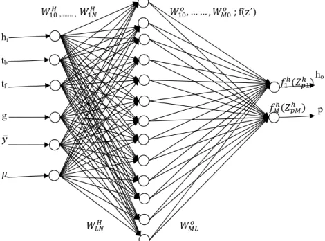
Figure 4. Neural Network with N inputs, M outputs and L neurons in the hidden layer. ... 14
Figure 5. Simple model of transformer winding, HV = disc, LV = layer. These same notations are used in the calculation of the effective surface heat transfer coefficient. ... 17
Figure 6. Introduction of necessary parameters for the finite differential method ... 21
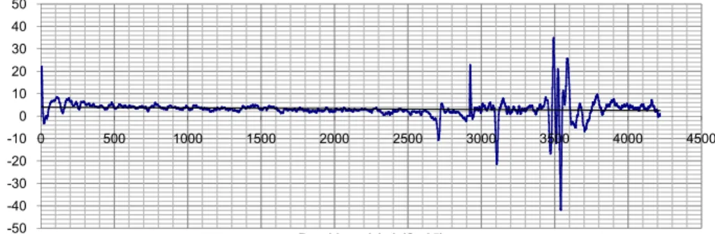
Figure 7. Measured thickness, eccentricity and total roll force ... 25
Figure 8. Flatness measured data for poor (top graph) and good (bottom graph) coil in the middle of a strip ... 26
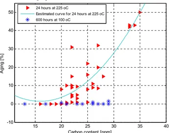
Figure 9. Ageing of a 0.35 mm thick slab measured at 1.5 T and 50 Hz. ... 27
Figure 10. Ageing vs time for the two different samples. ... 28
Figure 11. Dimensions of the three phase model core (mm), T-joint 60º. Figure 12. Dimensions of the single phase model core (mm). ... 29
Figure 13. Different joint designs: a) SSL (N = 1); b) MSL(N = 4) ; c) core joint stacking sequence (shown with one sheet per step). ... 29
Figure 14. Definition of core sheet overlaps and core joint gap size with a 60º T joint ... 31
Figure 15. Location of pressure application on model core yokes ... 32
Figure 16. High power reflector simulation in top and annealing furnace (Ugn) temperature simulation in the bottom. ... 35
Figure 17. Core and winding temperature, calculations in MATLAB ... 36
Figure 18. Distribution of heat in core of winding with OFAF power transformer (simulation by COMSOL software). ... 36
LIST OF TABLES
Table 1. Influence of ageing on magnetic properties [Data was obtained from Trans P. P. Lab.] 27 Table 2. Reference building factors - three phase cores ... 29Table 3. Reference building factors - single phase cores ... 29
Table 4. Increase in building factor (%) for non step lap versus step lap stacking... 30
Table 5. Increase in exciting current (%) for non step lap versus step lap stacking ... 30
Table 6. Increase in building factor (%) two sheets per step versus one sheet per step ... 30
Table 7. Increase in building factor (%) DR and HI-B materials versus RGO material ... 30
Table 8. Building factor comparison for different core designs RGO and DR material ... 30
Table 9. Loss increase due to gap size for DR material - three phase and single phase ... 31
Table 10. Exciting current increase (%) due to gap size for DR material – three phase and single phase ... 31
Table 11. Summary of core loss increase for different clamping cases ... 32
LIST OF FIGURE
Figure 1. Equivalent circuit diagram of transformer in the top, induction machine in the middle
and power flow diagram of induction machine in the bottom. ... 7
Figure 2. Proposed control idea with entry and exit thickness gauge, with laser speed measurement and with tension feed-forward. ... 8
Figure 3. Thesis flowchart ... 10
Figure 4. Neural Network with N inputs, M outputs and L neurons in the hidden layer. ... 14
Figure 5. Simple model of transformer winding, HV = disc, LV = layer. These same notations are used in the calculation of the effective surface heat transfer coefficient. ... 17
Figure 6. Introduction of necessary parameters for the finite differential method ... 21
Figure 7. Measured thickness, eccentricity and total roll force ... 25
Figure 8. Flatness measured data for poor (top graph) and good (bottom graph) coil in the middle of a strip ... 26
Figure 9. Ageing of a 0.35 mm thick slab measured at 1.5 T and 50 Hz. ... 27
Figure 10. Ageing vs time for the two different samples. ... 28
Figure 11. Dimensions of the three phase model core (mm), T-joint 60º. Figure 12. Dimensions of the single phase model core (mm). ... 29
Figure 13. Different joint designs: a) SSL (N = 1); b) MSL(N = 4) ; c) core joint stacking sequence (shown with one sheet per step). ... 29
Figure 14. Definition of core sheet overlaps and core joint gap size with a 60º T joint ... 31
Figure 15. Location of pressure application on model core yokes ... 32
Figure 16. High power reflector simulation in top and annealing furnace (Ugn) temperature simulation in the bottom. ... 35
Figure 17. Core and winding temperature, calculations in MATLAB ... 36
Figure 18. Distribution of heat in core of winding with OFAF power transformer (simulation by COMSOL software). ... 36
LIST OF TABLES
Table 1. Influence of ageing on magnetic properties [Data was obtained from Trans P. P. Lab.] 27 Table 2. Reference building factors - three phase cores ... 29Table 3. Reference building factors - single phase cores ... 29
Table 4. Increase in building factor (%) for non step lap versus step lap stacking... 30
Table 5. Increase in exciting current (%) for non step lap versus step lap stacking ... 30
Table 6. Increase in building factor (%) two sheets per step versus one sheet per step ... 30
Table 7. Increase in building factor (%) DR and HI-B materials versus RGO material ... 30
Table 8. Building factor comparison for different core designs RGO and DR material ... 30
Table 9. Loss increase due to gap size for DR material - three phase and single phase ... 31
Table 10. Exciting current increase (%) due to gap size for DR material – three phase and single phase ... 31
Table 11. Summary of core loss increase for different clamping cases ... 32
Table 12. HST magnitude and location ONAN cooling mode. ... 36
1
1. INTRODUCTION
The core is an essential part of transformers, generators, motors and other electrical equipment. Cores flux and voltage is used to run motors, generate electricity and is converted in transformers. Most of the attention on cores relates to its materials, magnetic properties, loss properties and polarisation. The noise level may also be improved in the production step. High polarization and magnetic flux density (about 1.8 Tesla) along with lower iron losses is interesting to produce of electrical strips.
One of the main components of the strip is silicon. Increasing silicon in oriented and aluminium in non oriented steels strip increases resistivity, reduces eddy losses, increases permeability, and prevents ageing in an auxiliary form [1]. Silicon can therefore reduce losses but can also cause problems in the rolling process. It increases fragility of the strip as it passes through the working rolls of cold rolling mills. Higher silicon content can also decrease the grain size value, causing unsuccessful secondary recrystallization, which increases iron loss [1]. The hysteresis loss is reduced as a result of the very low levels of impurities and low internal stress in the steel. A study of losses in core-containing electrical equipment must consider the production and assembly steps as well as the operating lifetime of the core. The main losses in production occur during hot rolling; annealing and cold rolling [2]. Losses during hot rolling usually relate to the properties of the material and are not discussed in this thesis. Cold rolling and annealing are secondary process, and are discussed here. The thickness, grain size, flatness and decarburization of the slab are among the properties that are controlled by the cold rolling and annealing processes. Variables such as the roll gap force, roll bending force, back and forward tension and slab speed affect these properties and can be controlled during the cold rolling process. Irregular thickness and thickness above the predefined value increase the eddy current losses. Uniform strips have been shown empirically to be more efficient [2].
The cold rolling process is one of the main processes in strip production. The microstructure of steel changes during cold rolling. Hot rolling uses high temperature and tandem stands to reduce the strip thickness. The strip then undergoes the cold rolling process. Cold rolling enhances several properties of the hot-rolled strip - it increases smoothness of the strip surface, increases mechanical strength, yield strength, tensile strength and hardness, and reduces ductility [3]. Post rolling further improves the strip quality, but to a lesser degree than the improvement effected by cold rolling. Thickness control in cold rolling system will be done from entrance strip in coil to exit strip after process with the uniformity of width, thickness, hardness, etc. [3] and [4].
As mentioned above cold rolling has a major effect on strip magnetic ageing and thickness. Reduction of inconsistencies in the cold rolling process, such as thickness, eccentricity, flatness deviations and loose edges are therefore desirable. Carbon content, which contributes to increase aging [5] may be increased by impurities and dirty strip surfaces during the cold rolling process. Carbon contamination in annealing furnaces and after cold rolling can be reduced by decarburization of annealing furnaces and cleaning of the strip after cold rolling and before rewinding.
Sheet quality can be increased before cold rolling by processes such as pickling. Scale and oxides that remain after hot rolling are removed in this step. Pickling prevents oxides being rolled into the strip surface and causing defects during cold rolling.
The desired thickness of strips is achieved by cold rolling [6], which also increases strength. Maximum hardness of the strips is achieved with thickness reductions greater than 50%. This is followed by the annealing process [7] Annealing reduces the grain structure. The aim of this is to
increase flatness, achieve the final finish and texture, improve the mechanical properties and reduce the possibility of stretching and straining during forming.
Temperature distribution and decarburization have additional effects on the annealing process. A defined constant and uniform temperature must be maintained throughout the annealing process in order to achieve the required grain size. Failing to maintain a uniform temperature during annealing results in the wrong grain size, which can lead to increased losses due to hysteresis [2]. Gas fired furnaces are usually currently used in the annealing process.
Assembly is another process where accuracy is crucial. The dimensions, physical, and thermal effects as well as construction of the core can affect losses. A number of core assembly parameters, such as core quality, joint stacking and clamping pressure can affect the performance of stacked cores. These attributes are considered for different core material grades, and for single phase and three phase cores. Measured parameters in this research are core losses and core exciting current. The building factor defines the losses incurred during assembly. Its value is defined at the design stage [8].
Electrical equipment undergoes ageing in operation. The main contributor to this process is the carbon content of strips. Temperature hot spots and temperature gradients in the equipment also increase the rate of ageing. Utilities are interesting to slow down ageing. Auxiliary or permanent apparatus should be installed on the equipment to maintain the temperature within predefined limits. Improvements in cooling systems and installation of auxiliary apparatus such as oil spraying systems can therefore reduce losses in large scale transformers.
The two classes of electrical equipment that use clustered strips in their cores are transformers and rotating machines, such as electric motors. The cores used in these two applications differ in how they are rolled. Grain oriented strips are used in transformer cores and non grain oriented strips are used in rotating machines. However non oriented strips can be used in either class of equipment. Non oriented electrical steel is less expensive and is used in applications where the direction of magnetic flux is variable. Grain oriented steel is more expensive and direction of magnetic flux is parallel to the rolling direction.
Reduction of eddy current losses necessitates the use of thin strips. This is difficult to attain by rolling. Strip thicknesses of 0.23 mm are currently attainable. Manufacture of strips thinner than this has been attempted, but has been unsuccessful due to unsuccessful secondary recrystallization. Failed recrystallization leads to increased iron loss. It may be possible to recover the recrystallisation with higher quality annealing.
As mentioned above there are several steps that may be taken to reduce losses in core production. Another way to improve core efficiency may be to create fractionating magnetic domains by plasma jet or by setting up local areas of strain on the surface of the strip [9] and [2].
Other approaches to improving the magnetic characteristics in the rolling direction have attempted to recover magnetic flux distribution and diffusion in the strips and cores. For this the crystal grains have to be gathered in the Goss orientation, (110) [001]. This can be achieved through secondary recrystallization in the final finish annealing [2].
In this type of secondary recrystallization, crystal grain growth around the (110) [001] orientation is selectively permitted while growth in other orientations is restrained. Obstacles and obstructions should be added to stifle the crystal grain growth in unwanted orientations.
2 increase flatness, achieve the final finish and texture, improve the mechanical properties and reduce the possibility of stretching and straining during forming.
Temperature distribution and decarburization have additional effects on the annealing process. A defined constant and uniform temperature must be maintained throughout the annealing process in order to achieve the required grain size. Failing to maintain a uniform temperature during annealing results in the wrong grain size, which can lead to increased losses due to hysteresis [2]. Gas fired furnaces are usually currently used in the annealing process.
Assembly is another process where accuracy is crucial. The dimensions, physical, and thermal effects as well as construction of the core can affect losses. A number of core assembly parameters, such as core quality, joint stacking and clamping pressure can affect the performance of stacked cores. These attributes are considered for different core material grades, and for single phase and three phase cores. Measured parameters in this research are core losses and core exciting current. The building factor defines the losses incurred during assembly. Its value is defined at the design stage [8].
Electrical equipment undergoes ageing in operation. The main contributor to this process is the carbon content of strips. Temperature hot spots and temperature gradients in the equipment also increase the rate of ageing. Utilities are interesting to slow down ageing. Auxiliary or permanent apparatus should be installed on the equipment to maintain the temperature within predefined limits. Improvements in cooling systems and installation of auxiliary apparatus such as oil spraying systems can therefore reduce losses in large scale transformers.
The two classes of electrical equipment that use clustered strips in their cores are transformers and rotating machines, such as electric motors. The cores used in these two applications differ in how they are rolled. Grain oriented strips are used in transformer cores and non grain oriented strips are used in rotating machines. However non oriented strips can be used in either class of equipment. Non oriented electrical steel is less expensive and is used in applications where the direction of magnetic flux is variable. Grain oriented steel is more expensive and direction of magnetic flux is parallel to the rolling direction.
Reduction of eddy current losses necessitates the use of thin strips. This is difficult to attain by rolling. Strip thicknesses of 0.23 mm are currently attainable. Manufacture of strips thinner than this has been attempted, but has been unsuccessful due to unsuccessful secondary recrystallization. Failed recrystallization leads to increased iron loss. It may be possible to recover the recrystallisation with higher quality annealing.
As mentioned above there are several steps that may be taken to reduce losses in core production. Another way to improve core efficiency may be to create fractionating magnetic domains by plasma jet or by setting up local areas of strain on the surface of the strip [9] and [2].
Other approaches to improving the magnetic characteristics in the rolling direction have attempted to recover magnetic flux distribution and diffusion in the strips and cores. For this the crystal grains have to be gathered in the Goss orientation, (110) [001]. This can be achieved through secondary recrystallization in the final finish annealing [2].
In this type of secondary recrystallization, crystal grain growth around the (110) [001] orientation is selectively permitted while growth in other orientations is restrained. Obstacles and obstructions should be added to stifle the crystal grain growth in unwanted orientations.
3 Electrical steel cores generate heat during operation. In order to test that the magnetic properties do not deteriorate under working conditions, the steel can be tested for magnetic ageing. For electrical steels, the term ‘magnetic ageing’ refers to the increase in loss after a heat treatment of the finished product. The European standard defines the test cycle as 225°C for 24 h [10]. The American ASTM standard suggests two different cycles one of those is: 100 hours at 150°C or 600 h at 100 °C [11].
Ageing occurs as a result of the formation of different types of iron carbides that hinder domain wall motion [11].
• At T>250°C, or for long soaking below this temperature, cementite (Fe3C) particles are
formed.
• At 100°C<T<250°C, ε-carbides of the approximate composition Fe2.4C are formed.
• At T<100°C, very fine carbides are formed, typically between 20 and 40 nm.
The precipitates that are most harmful for the magnetic properties are of size 0.1 to 1.0 µm. The low temperature carbides do not contribute to ageing [11]. Their influence on losses is investigated in the attached paper (paper number 4).
In summary, reduction of core losses requires optimization of the core production process to increase the quality of parameters such as flatness, thickness, shape, crystallization and grain size, and technical and non-technical optimization of transformer and hopefully electrical rotating machines. This thesis focuses on transformer and electrical rotating machine cores. In addition, due its importance in strip processing, the role of cold rolling will also be discussed.
The author focuses on electromagnetic losses in the core and windings of transformers using the methods, governing equations and computer simulations that were proposed based on his previous research published in his licentiate thesis [12].
The licentiate thesis examined the role of temperature distribution in the core and windings, and the hottest spot temperature. The influence of process control on losses was evaluated and a novel device to reduce the hottest spot temperature, called the oil spraying system, was proposed. Another potentially effective way to reduce losses may be through controlling the strip thickness. A study of cold rolling and annealing is presented. Thickness estimated using ANN method. The research described in this thesis focuses on process control of the cold rolling system and annealing to achieve accurate and precise thickness. Multivariable data analysis in the cold rolling system was carried out to find the control system variable correlations. Correlated and inversely correlated variables for better control of the cold rolling system were identified. A modern improved control system was used with the control model of the cold rolling system, and the results supported a role for increasing the accuracy of the final thickness in improving the loss properties of slabs and cores. Parameters from the automation system and measured values from the cold rolling process and operations were used to validate the model and to identify the important sources of disturbances. The results are presented in the following sections.
1.1
PAPERS CONNECTIONSElectrical phenomena are examined in transformers initially, and then in electroplates (sheets) used in transformers, motors, generators, furnaces and other electrical equipment. In all cases heat is produced due to electrical losses. In transformers the heat is negative, and cooling is needed. For electroplates the task is to produce a sheet that is thin and homogenous, to reduce losses in the equipments it is used in. For the Kanthal furnace the “losses” are desirable, as its
purpose is to produce as much heat as possible, but the heat needs to be directed to the right place. This thesis investigates the control of electrical and thermal equipment by optimization using numerical, FEM and CFD modeling in combination with dynamic simulation models. Six papers are attached to this thesis. Paper 1 describes a high electric power reflector designed by Kanthal AB and optimized by the author. This system can generate 1910 K on the element and the temperature 20 cm above the element can reach 1700 to 1800 K. Simulation of the system shows that it can be used in the annealing furnaces of strip production processes.
Paper 2 considers the cold rolling control system and investigates the roles of eccentricity, thickness, roll gap forces, coolant system, Smith predictors, Kalman predictors and other control variables.
Paper 3 presents an analysis of data collected by the automation system using Unscrambler software. Results will be used to coordinate the cold rolling control system. This paper presents a discussion of co varied and inversely co varied variables and identifies roll gap force, roll bending forces, eccentricity and ASD as the most important parameters for controlling the system.
Paper 4 presents a study of ageing in electrical strips, and investigates the effects of impurities on ageing.
Paper 5 discusses identification of thickness using a neural network and the design of an adaptive control system to control the strip variables. This paper also includes online and offline investigation of the control system of the cold rolling mill.
Paper 6 presents the application of the oil spraying system. The temperature in the hot spot before and after using the oil spraying system is calculated and the temperature profile is simulated. The effect of the nozzle cross section on cooling and the heat transfer coefficient are discussed. The results of the papers and technical reports can be briefly summarised as:
Review of the tools for loss reduction:
• Laminate: thinly rolled - restrains eddy currents but is expensive and impairs space occupancy.
• Alloy: adding silicon raises resistivity but lowers saturation magnetisation.
• Purification: removes inclusions - aids domain wall motion, reduces hysteresis loss. • Use of large grains: reduces hysteresis loss.
• Use of beneficial ‘texture’: a whole science of grain growth and its control exists. • Application of tensile stress: coatings help with this.
• Optimisation of building factor: reduces the core iron losses
• Use of auxiliary coolant in the machines and the oil spraying system in the power transformers: reduces the hot spot temperature and increases loading
Insufficient flatness of a cold rolled electrical strip can be due to process-related factors such as: • Insufficient coolant pressure, resulting in the formation of "longitudinal waves".
• Undesired bending of one or both work rolls causes the electrical strip to be concave or convex in cross-section.
• Imperfectly and incorrectly controlled spray jets for applying cooling medium - leading to metal strip of irregular cross-section.
• Insufficient surface quality of working rolls, resulting in irregularities running in the longitudinal and transverse direction in the electrical strip.
1.2. L
ITERATURE REVIEWSProcess analysis and the selection of numerical methods for each process have been studied by Leiviska [13]. Artificial neural network (ANN), Adaptive control, Fuzzy logic and other
4 purpose is to produce as much heat as possible, but the heat needs to be directed to the right place. This thesis investigates the control of electrical and thermal equipment by optimization using numerical, FEM and CFD modeling in combination with dynamic simulation models. Six papers are attached to this thesis. Paper 1 describes a high electric power reflector designed by Kanthal AB and optimized by the author. This system can generate 1910 K on the element and the temperature 20 cm above the element can reach 1700 to 1800 K. Simulation of the system shows that it can be used in the annealing furnaces of strip production processes.
Paper 2 considers the cold rolling control system and investigates the roles of eccentricity, thickness, roll gap forces, coolant system, Smith predictors, Kalman predictors and other control variables.
Paper 3 presents an analysis of data collected by the automation system using Unscrambler software. Results will be used to coordinate the cold rolling control system. This paper presents a discussion of co varied and inversely co varied variables and identifies roll gap force, roll bending forces, eccentricity and ASD as the most important parameters for controlling the system.
Paper 4 presents a study of ageing in electrical strips, and investigates the effects of impurities on ageing.
Paper 5 discusses identification of thickness using a neural network and the design of an adaptive control system to control the strip variables. This paper also includes online and offline investigation of the control system of the cold rolling mill.
Paper 6 presents the application of the oil spraying system. The temperature in the hot spot before and after using the oil spraying system is calculated and the temperature profile is simulated. The effect of the nozzle cross section on cooling and the heat transfer coefficient are discussed. The results of the papers and technical reports can be briefly summarised as:
Review of the tools for loss reduction:
• Laminate: thinly rolled - restrains eddy currents but is expensive and impairs space occupancy.
• Alloy: adding silicon raises resistivity but lowers saturation magnetisation.
• Purification: removes inclusions - aids domain wall motion, reduces hysteresis loss. • Use of large grains: reduces hysteresis loss.
• Use of beneficial ‘texture’: a whole science of grain growth and its control exists. • Application of tensile stress: coatings help with this.
• Optimisation of building factor: reduces the core iron losses
• Use of auxiliary coolant in the machines and the oil spraying system in the power transformers: reduces the hot spot temperature and increases loading
Insufficient flatness of a cold rolled electrical strip can be due to process-related factors such as: • Insufficient coolant pressure, resulting in the formation of "longitudinal waves".
• Undesired bending of one or both work rolls causes the electrical strip to be concave or convex in cross-section.
• Imperfectly and incorrectly controlled spray jets for applying cooling medium - leading to metal strip of irregular cross-section.
• Insufficient surface quality of working rolls, resulting in irregularities running in the longitudinal and transverse direction in the electrical strip.
1.2. L
ITERATURE REVIEWSProcess analysis and the selection of numerical methods for each process have been studied by Leiviska [13]. Artificial neural network (ANN), Adaptive control, Fuzzy logic and other
5 numerical methods have been used to derive a model of the system which uses of multivariable data and numerical methods [14], [15], [16] [7] and [17]. Thickness prediction in a cold rolling mill without time delays is of great interest to manufacturers, and has been investigated by Zarate [18], [19], who used an ANN method to increase the accuracy of thickness prediction. The model was trained and successfully predicted thickness accurately. The Zarate model might be further improved by combining offline and online methods. Formanek [20] studied basic control functions and concepts and focused on process automation. They presented the capability of ABB in the control system of cold rolling mills. Wang [21] has used the Smith predictor with an ANN method to increase the response speed of the model and achieve to self adaptability of the system. The Smith predictor that they used requires a highly accurate model of the system and has poor adaptive performance to changes in related parameters. Using an optimized Smith predictor and
an ANN method, the time delay due to the installation of a shape meter downstream of the cold rolling system was decreased. Identification of the important variables in the cold rolling using multivariable data analysis has not been done up to now. The majority of studies relate to the metallurgy, and analyse the data by conventional data analysis methods. The correlations between the cold rolling variables remain to be studied.
Finding a suitable replacement for the gas fired system in annealing furnaces to overcome non-homogenous grain size and to remove stresses is one of the main priorities for strip manufacturers.
Ageing is one of the main problems in working transformers and rotating machines. Broddefalk [5] examined the high dew point problem and decarburization in slab surfaces. They attempted to decrease ageing problems by reducing the carbon content in the slabs
Temperature hot spots are formed in transformers as a result of heat generated due to electrical and magnetic losses. Hot spots reduce the component lifetime and accelerate ageing [22], [23], and [24]. A numerical method that uses the conventional governing equation is used to calculate HST [24], [25], [26], [27] and [28]. The heat transfer process occurs over several complicated surfaces and is dependent on the temperature rise and other parameters. In reality, the core and windings of transformers immersed in oil do not have a uniform temperature profile. Accurate domain and boundary conditions must be defined to simulate the temperature distribution and to find the HST. Over the last 36 years, several methods of calculating the HST have been presented. To find HST, Alen added a constant value to the winding temperature and top of oil temperature [29].
The IEC standard [30] and [31], defines the average temperature rise of a transformer winding. Under this standard, rises exceeding 65°C is not acceptable. In IEC 76, under the effect of time and temperature, the rate of ageing of the interterm insulation of transformers is referenced against a hot spot temperature of 98°C, for example to a value that normally corresponds to a 20°C cooling air temperature under the continuous rated load [30].
IEC 354 and IEEE standards [32] and earlier authors [28] recommend different maximum allowed temperatures for different insulating materials. For Class A insulating materials, under overloads of short duration it is 105°C and 140°C is allowed as the highest hot spot temperature, whereas 250°C is an average winding temperature in copper windings, and 200° C is allowed for aluminium windings in short circuit conditions [32] and [33].
Although previous authors have investigated the estimation of the hot spot position, they have only removed some of the obstacles and their work does not solve all the problems involved [34], [35], [36], [37] and [38]. For example, the temperature distribution has only been evaluated for oil flow in a horizontal duct, meaning that the heat conduction equation is expressed in cylindrical coordinates. However, this only considers the heat transfer that occurs by conduction
within the laminar flow The simult temperature winding [3 [44] and [4 A valuable [47], [48] a Overheated small amou The higher has been s temperature The simula T-joint. The current and rated volta Therefore, t
1.3.
RO Simple circ evaluation o In Figure 1 machine. R rotor leakag The red circ1 MZS, A syn fixed layer w. taneous dep e (HST) is a 9] and the d 5]. treatment o and [49]. d cores can unts of hyd the core ho uggested th e a core sho ation in [12] e HST valu d 5% over th ge without the core HS TATING MA cuit and p of losses ar 1, Pin is inp R in the figu ge reactance cle in the fi nchronous machin of the fluid piction of a complex p dynamic na of the therm lead to hy drogen are g ot-spot temp hat 130 ºC ould experie showed tha ue of the cor he rated vo load. Duri ST is lower ACHINES A ower flow e presented put electric ure relates to e and Xm re gure shows Po In
ne, FKEE, UMP
d. These stu two tempe process, fur ature of the mal aspects o ydrogen gas generated a perature, th would be ence in any at the hottes re hot spot ltage [52]. ing no load than that oc AND TRANS diagrams d in Figure 1 power; Rc o stator and epresents the the core lo ower transfo nduction m udies were b erature zon rther compli load and a of a transfor ssing. The at core hot s he higher is a reasonab of its possi st spot of th is generally The highest d operation ccurring at t SFORMER of rotating 1. is the core d rotor wind e magnetizi sses in the c ormer circu motor circuit based on an nes, top of icated by th ambient tem rmer has be data presen spot temper the rate of ble limit for ible operatin he core is of y created un t core temp the top oi the 105% no CIRCUIT D g machines e loss in th ding resistan ing reactanc circuit, whic uit diagram diagram1 nd limited t f oil (TOT he thermal h mperature [4 een reported nted in [12] ratures as l gassing. Ba r the maxim ng scenario ften located nder the tran perature rise il temperatu ominal volt DIAGRAM and powe he stator sid nce, X repre ce per phase ch are the fo to heat tran T) and hott heterogeneit 40], [41], [4 d very recen ] demonstra ow as 110– ased on this mum core s [50], [51] d in the cent nsformer’s e occurs at ure is much tage and cur
er transform de of the in esents the st e. focus of this nsfer in a test spot ty of the 42], [43], ntly [46], ates that –120 ºC. s data, it hot spot and [8]. tre of the full load 110% of h lower. rrent. mers for nduction tator and s thesis.
within the laminar flow The simult temperature winding [3 [44] and [4 A valuable [47], [48] a Overheated small amou The higher has been s temperature The simula T-joint. The current and rated volta Therefore, t
1.3.
RO Simple circ evaluation o In Figure 1 machine. R rotor leakag The red circ1 MZS, A syn fixed layer w. taneous dep e (HST) is a 9] and the d 5]. treatment o and [49]. d cores can unts of hyd the core ho uggested th e a core sho ation in [12] e HST valu d 5% over th ge without the core HS TATING MA cuit and p of losses ar 1, Pin is inp R in the figu ge reactance cle in the fi nchronous machin of the fluid piction of a complex p dynamic na of the therm lead to hy drogen are g ot-spot temp hat 130 ºC ould experie showed tha ue of the cor he rated vo load. Duri ST is lower ACHINES A ower flow e presented put electric ure relates to e and Xm re gure shows Po In
ne, FKEE, UMP
d. These stu two tempe process, fur ature of the mal aspects o ydrogen gas generated a perature, th would be ence in any at the hottes re hot spot ltage [52]. ing no load than that oc AND TRANS diagrams d in Figure 1 power; Rc o stator and epresents the the core lo ower transfo nduction m udies were b erature zon rther compli load and a of a transfor ssing. The at core hot s he higher is a reasonab of its possi st spot of th is generally The highest d operation ccurring at t SFORMER of rotating 1. is the core d rotor wind e magnetizi sses in the c ormer circu motor circuit based on an nes, top of icated by th ambient tem rmer has be data presen spot temper the rate of ble limit for ible operatin he core is of y created un t core temp the top oi the 105% no CIRCUIT D g machines e loss in th ding resistan ing reactanc circuit, whic uit diagram diagram1 nd limited t f oil (TOT he thermal h mperature [4 een reported nted in [12] ratures as l gassing. Ba r the maxim ng scenario ften located nder the tran perature rise il temperatu ominal volt DIAGRAM and powe he stator sid nce, X repre ce per phase ch are the fo to heat tran T) and hott heterogeneit 40], [41], [4 d very recen ] demonstra ow as 110– ased on this mum core s [50], [51] d in the cent nsformer’s e occurs at ure is much tage and cur
er transform de of the in esents the st e. focus of this 6 nsfer in a test spot ty of the 42], [43], ntly [46], ates that –120 ºC. s data, it hot spot and [8]. tre of the full load 110% of h lower. rrent. mers for nduction tator and s thesis. 6 7
Figure 1. Equivalent circuit diagram of transformer in the top, induction machine in the middle and power flow diagram of induction machine in the bottom.
1.4. T
ECHNOLOGYC
ONTROLA brief discussion of control system technology follows. An understanding of the parameters and diagrams will help to better understand the control process that is considered in the appended papers. Automatic control systems are preferred to manual control for the cold rolling process to ensure a higher quality of strip. Automatic control increases the efficiency and reduces defects. A professional process automation system with adaptive control and intelligent adjustment of controller parameters can be realized this concept. Control algorithms are used in rolling mills to maintain optimal dynamic performance under different process conditions.
Several controllers are used in rolling mills. Feedback is applied to the variables to achieve higher quality with near to set point values of final requirements. Tolerances between the actual value at the output and the set point value are calculated and error is applied to the controller. The controller changes the work roll gap, which is regulated either by the position or a roll force control loop in the thickness control method.
The cold rolling control model is able to control the process using the thickness feedback control, speed feedforward control, Morgoil bearing compensation (if the backup roll bearing is of Morgoil type) and wedging control (if required by the rolling schedule) (see Figure 2) [20]. Smith Predictor feedback is applied to the thickness feedback control loop as software in the system. Thickness feedforward is applied to the control model using a thickness gauge at the entry side of the roll gap. Thickness deviation in entry thickness can be compensated. A shift register track is used at the entry to measure the thickness. A correction value is computed consistent with the saved entry thickness deviation and forwarded to the roll gap control system when the strip reaches the work roll gap.
The mass flow equation is used to modify both control system layout and parameters [20]. High control system dynamics with high control accuracy can be achieved by applying this concept. This provides a clear improvement in quality in results from thickness feedback and thickness feedforward. In this way, the following subsystems can be incorporated: tension feedforward control to the pay-off reel and mass flow control with thickness feedback control are included in the control loop.
Pin (stator) Pin (air gap) Pm (mechanical) Pout
√3�������������
Pscu(copper loss) Pin (core loss) PRcu (copper loss) Pwindage, friction
3����� �������� 3��,���� 3�� � ,� ��� 3��� ,�� � �� � ���

![Figure 2. Proposed control idea with entry and exit thickness gauge, with laser speed measurement and with tension feed-forward (Extend model of reference [20])](https://thumb-eu.123doks.com/thumbv2/5dokorg/4830448.130340/20.718.102.608.68.364/figure-proposed-control-thickness-measurement-forward-extend-reference.webp)