VTI sär
tr
yck 352 • 2002
Safety belts in lifeboats
Evaluation and dynamic tests for improved launch safety
M Sc Thesis
by
Anders Hansson
Andreas Stolt
NAVAL ARCHITECTURE November 2002
DEPARTMENT OF VEHICLE ENGINEERING
Address Visiting address Telephone Fax
Naval Architecture Teknikringen 33 +46 8 790 60 00 (switch) +46 8 790 66 84
Safety belts in lifeboats
-Evaluation and dynamic tests
for improved launch safety
M Sc Thesis by Anders Hansson Andreas Stolt TRITA-FKT ISSN 1103-470X ISRN KTH/FKT/SKP/EX--02/36--SE
Abstract
The purpose of this thesis was to analyse if a combined safety-belt/lifejacket system could protect the occupants of a lifeboat during the evacuation phase, and obtain data about human tolerance levels for the occupants.
Crash tests were made at the crash test track at VTI, Linköping, with a slightly modified bench arrangement of a typical lifeboat.
27 tests were made at VTI, simulating impacts of the lifeboat against the mother ship and drops with the lifeboat into the water. With the use of crash test dummies with accelerometers and high-speed cameras, results were obtained about the risk of injuries.
The result was that a safety belt system improves the safety onboard. An idea for the design of a combined lifejacket/safety-belt system is presented. Some changes of the design of the benches onboard the lifeboat has also been suggested. These are the use of padding inside the lifeboat, a semi-flexible board on the edges of the bench and an elastic back support band for the higher benches. The results and suggested changes are presented in chapter 8 Conclusions.
Keywords: acceleration, crash, crash test, dynamic test, evacuation, ferry, human tolerance, injury, launch, lifeboat, lifejacket, life vest, padding, passenger, passenger ship, personal floating device, risk analysis, ship, ship motion
Acknowledgements
Ylva Matstoms and the rest of the researchers at the Crash Safety, VTI, for their support during the work with the project.
Elena Tsychkova, PhD student at Div. of Naval Architecture, KTH, for the help with the project.
Professor Olle Rutgersson, supervisor at KTH, at present Maritime school, Chalmers Lindholmen, for giving us free reins.
Thomas Turbell, Research Director Crash Safety, VTI, and supervisor at VTI, for the support during this project.
The crew onboard M/S Silja Symphony and M/S Finnarrow for their support during the visits onboard.
Abbreviations
CE Comité Européen (European Committee)
DNV Det Norske Veritas
DRM Dynamic Response Model
EU European Union
FEM Finite Element Analysis
IMO International Maritime Organisation
KTH Royal Institute of Technology
LR Lloyd’s Register
LTH Lund Institute of Technology
NTHSA National Highway and Traffic Safety Administration PELB Partially Enclosed Lifeboat
RN Royal Navy
Ro-Ro Roll on-Roll off
SAE Society of Automotive Engineers
SOLAS Safety Of Life At Sea
SRSS Square-Root Sum of the Squares
TELB Totally Enclosed Lifeboat
UK United Kingdom
UN United Nations
VINNOVA Swedish Agency for Innovation Systems
Contents
1 Introduction ... 1
2 Background... 2
2.1 The Embarkation situation ... 2
2.1.1 General ... 2 2.1.2 Potential risks ... 3 2.1.3 Accident statistics... 5 2.2 Earlier studies... 7 2.2.1 Background ... 7 2.2.2 Related areas ... 8
2.2.3 Related facts and conclusions ... 8
2.2.4 The risk estimation... 10
2.3 Motions and accelerations... 12
2.3.1 General ... 12
2.3.2 The lateral impacts ... 13
2.3.3 The bottom impacts... 14
3 Human biomechanics ... 16
3.1 General ... 16
3.1.1 Injury patterns ... 16
3.1.2 Severe injuries ... 16
3.1.3 Safety belt positions ... 16
4 Lifeboats and models ... 19
4.1 Present day lifeboats... 19
4.1.1 General ... 19
4.1.2 Models... 20
4.1.3 Classification... 27
4.2 Modulating the lifeboat ... 28
4.2.1 General ... 28
4.2.2 Limitations ... 28
4.2.3 Analysis of risks ... 29
4.2.4 Benches ... 31
4.2.5 Manufacture ... 33
4.2.6 The final platform ... 35
5 Lifejackets and improvements ... 37
5.1 Present day lifejackets... 37
5.1.1 Generally about lifejackets... 37
5.1.3 Buoyancy lifejackets ... 40
5.1.4 Inflatable lifejackets ... 41
5.2 Improvements of the lifejacket... 43
5.2.1 Purpose ... 43
5.2.2 Inquired lifejackets... 44
5.2.3 Evaluation... 47
5.2.4 Initial assemblies... 48
5.2.5 Conclusive assembly... 49
6 Test facilities and test equipment... 52
6.1 Test equipment ... 52
6.1.1 Crash test track ... 52
6.1.2 Crash test sled ... 54
6.1.3 Dummies ... 55
6.1.4 Sensors ... 58
6.1.5 Benches ... 58
6.1.6 Miscellaneous... 59
7 Tests and test analysis ... 62
7.1 Test groups ... 62
7.2 Test analysis ... 63
7.2.1 Correspondence between tests and lifeboat demands... 63
7.3 Pre-tests ... 64
7.3.1 Test 1-14... 64
7.4 Test group 1... 64
7.4.1 Test 15 ... 64
7.4.2 Test 16 ... 70
7.4.3 Test group conclusion ... 76
7.5 Test group 2... 79
7.5.1 Test 17 ... 79
7.5.2 Test 18 ... 83
7.5.3 Test 19 ... 87
7.5.4 Test 20 ... 90
7.5.5 Test group conclusion ... 92
7.6 Test group 3... 94
7.6.1 Test 21 ... 94
7.6.2 Test 22 ... 98
7.6.3 Test 23 ... 101
7.6.4 Test 24 ... 105
7.6.5 Test group conclusion ... 109
7.7 Test group 4... 111
7.7.1 Test 25 ... 111
7.7.2 Test 26 ... 114
7.7.4 Test group conclusion ... 120
7.8 Comparisons and results ... 121
8 Conclusions ... 122
8.1 Conclusions on the lifejacket/safety-belt system ... 122
8.2 Conclusions on the benches ... 123
8.2 Conclusions on the human tolerance ... 124
8.2 Suggested further work ... 124
9 References ... 125
Appendix 1.1 SOLAS Regulation A.689(17) regarding lifejackets ... 128
Appendix 1.2 Historical review ... 132
Appendix 1.3 Acceleration graphs... 138
Appendix 1.4 Manufacture drawings on benches ... 177
Appendix 1.5 Weights and dimensions of the Hybrid II 50th Male dummy... 187
Appendix 1.6 Weights and dimensions of the Hybrid III 50th Male dummy ... 188
1
Introduction
This thesis is part of a larger research project from VINNOVA, the Swedish Agency for Innovation Systems. The main project is called “Human aspects during evacuation of passenger ships” and aims to “survey, study and forward the knowledge on how the human behaviour, ability and tolerance limits affects the efficiency and security in evacuation situations”.
The objective for this thesis is to analyse the relationship between different system solutions and human tolerance levels. I.e. how well different fastening systems protects the occupants in lifeboats, if large forces are applied. A further desire is also to develop ideas for a new type of life-vest where a safety belt should be implanted. In order to improve the lifeboat safety the thesis will present a general discussion on necessary rearrangements and conclude defined acceleration-values for reasonable safe impacts.
The theoretical studies concerned several different areas. The thesis merges the lifeboat and lifejacket theory together with the biomechanical and dynamic assumptions in order to achieve an understanding for the main problem. All theory is discussed in the first four chapters, where it also connects the thesis with previous work done on the subject.
Dynamic tests were performed with the theory as background. The actual tests and measurements were performed in cooperation with the Swedish National Road and Transport Research Institute (VTI) on their crash safety test track located in Linköping. The outcome and conclusions from the tests are considered in the last two chapters.
The theory for human tolerance as well as the conclusion of the dynamic test results is mainly based on Elena Tsychkova’s previous work (Ref.[1]) and on the expertise from the researchers at VTI (Ref.[2]). Technical matters concerning lifeboats and lifejackets are regulated by SOLAS (Ref.[3]).
2
Background
2.1
The embarkation situation
2.1.1 General
”Shipping is one of the most international of all the world's great industries - and perhaps one of the most dangerous. It has always been recognised that the best way of improving safety at sea is by developing international regulations that are followed by all shipping nations.”
The quotation above is taken from the International Maritime Organisation (IMO), (Ref.[4]). They have promoted the maritime safety worldwide since 1948 when the United Nations (UN) established them.
Figure 2.1 IMO (Ref.[4]) However, accidents do happen despite IMO’s hard work. Every eventuality can unfortunately not be counted for in real life. Today’s improved safety-systems are very reliable, no questions about it, but if there are a long chain of mistakes and errors an accident may still happen. Historically, one single human mistake could have a devastating effect for the complete ship safety. That is usually not the case nowadays. One can say that the development today is pointing in the right direction. Much work is still possible to do in certain fields.
If an accident still happen and are so extensive that no countermeasure takes any effect, one has to face a new fact: Evacuation of the staff and passengers. Perhaps isn’t it necessary to mention that is has to be the captain’s worse nightmare and darkest hour.
The way the embarkation is carried out depends of course on the installed equipment and systems on board. That is on the other hand governed by regulations, e.g. ship-type, speed-class, route and so on. There are a couple of generally different life-saving systems, for example lifeboats, rafts and capsules. However, in this thesis only the ordinary lifeboats are going to be evaluated
2.1.2 Potential risks
The statistics shows that evacuation of ships generally is a very risky business. There is much to think about, often in a very stressful environment, plenty of different sources for error and accidents are possible.
Figure 2.2 Evacuation on the S/S Titanic
“Woman and children first”
Figure 2.3 Evacuation on the S/S
Lusitania
The risks of interest for this thesis are however completely tied to the lifeboats movement in the lowering phase. No concern will therefore be taken to investigate things such as the human behaviour or logistic problems, although it surly is of great importunes for a safe embarkation.
Depending upon the lowering device and the condition of the sea, substantial motions on the lifeboat could occur, especially if it hits the ship or the surface. I.e. the influence of a side-impact or bottom-impact on the lifeboat, and thus the passengers in it could exceed acceptable limits for the human well being.
Side-impacts has a strictly mechanical background seeing that the lifeboat and the ship simply is one system that consists of two swinging pendulums who interferes with each other and gives rise to large lateral-motions on the lifeboat. See figure 2.4. I.e. if the roll-period and lowering-speed coincide badly, could large pendulum-motions be excited down to the lifeboats.
Bottom-impacts on the lifeboat are another source for rapid changes in motion and velocity. The bottom-impact is however more controllable then the side-impacts since trained staff usually are in charge of the launching procedure. Still, neither of the cases should be taken lightly because more than once has the lowering been uncontrolled or altogether too hasty.
Figure 2.4 A complex problem is to predict the corresponding motion on the lifeboat under
harsh conditions (Ref.[1]).
A summery of the corresponding variables for the embarkation, i.e. waves, roll-period, launching-height, launching-side, davit-type and so on give a large number of probable motion-cases. It’s hard to predict the outcome if the conditions are harsh and irregular. That’s also the main reason why lifeboat-drills always are performed in calm weather close to the port. Much could be said about the drills, however experience shows that the only way to cope with them in a safe way is to work in a calm environment.
Figure 2.5 Lifeboat-drill on “M/S
Norwegian Dream”. Note the weather
conditions.
A discussion about the evacuation problem with Risto Jussilainen, Chief officer on M/S Silja Symphony was made and the conclusion was that lifeboat-drills rarely passed by without incidents (Ref.[5]). The accidents related to the drills are of course minor compared to actual cases. It however indicates that the systems lack in main adaptability.
2.1.3 Accident statistics
Hardly anyone could have missed that a number of severe accidents have struck the shipping-industry in the last decades. Ships like Herald of Free Enterprise, Scandinavian Star, Jan Heweliusz and Estonia leave nobody unaffected. Because of the publicity surrounding accidents involving passenger Ro-Ro ships is it sometimes assumed that this type of ship is much more dangerous than others. The accident statistics presented below will reveal if there’s a reason for such assumptions.
Figure 2.7 Estonia Figure 2.8 Jan Heweliusz
Since there hasn’t been any material or statistics publicised that considers the thesis exactly, or at least anything hasn’t been found, a general discussion around accident statistics seems like the best compromise. The passenger Ro-Ro ship is very common, especially in Scandinavian waters. These types of ships are furthermore usually equipped with partially enclosed lifeboats, i.e. the type of lifeboat that will be further investigated later in the thesis.
In 1994 the classification society Lloyd's Register (LR) published the casualty statistics from the past five years (Ref.[6]). It showed that passenger Ro-Ro cargo loss rate per thousand ships was 2.3, i.e. the same as the average ship. However, when one considers loss of life at sea the picture changes. Between 1989 and 1994, the Lloyd's Register figures show that 4583 lives were lost in accidents at sea. Of these 1544 were lost in accidents involving passenger Ro-Ro cargo ships - exactly one third, even though Ro-Ro-Ro-Ro ships make up only a small fraction of world merchant marine tonnage.
This indicates that passenger Ro-Ro ships are involved in an average number of accidents but that the consequences of those accidents are far worse.
The classification society, Det Norske Veritas (DNV) published an study concerning the safety of Ro-Ro ships in 1983 which covered the years 1965-1982 (Ref.[6]). Of 341 casualties during the period, 217 were defined as serious and 36 resulted in the total loss of the ship.
The study showed that the most common causes of serious casualties were collisions (24%), machinery damage (17%), grounding (17%), shift of cargo and operational (16%), fire and explosion (14%).
The figures changed significantly when total losses were studied. Here the most common cause was shift of cargo and operational faults (43%), collision (25%) and fire and explosion (18%).
The DNV study showed that total losses as a result of a collision were much higher for Ro-Ro’s than for other ships (with only a 9% occurrence). Both collisions and uncontrolled shifts of cargo frequently led to serious consequences with Ro-Ro’s. The paper noted that more than 70% of all Ro-Ro total losses due to collision resulted in loss of lives. 60% of the capsized ships caused by collisions sunk in less than ten minutes.
Figure 2.11 and 2.12 Two very spectacular accidents. Both passenger ships sunk after
showed that pure freight Ro-Ro’s more frequently was exposed to serious casualties and total losses. They have a high percentage share of all casualties and especially of total losses. Passenger ferries, on the other hand, had a fairly high percentage share of all categories but the serious casualty/total loss frequency was however relatively low. An interesting thing about the report is that it shows that the total loss rates for Ro-Ro’s always have been about the same over the years, approximately 2.5 per thousand ships. The average ship on the other hand, not only concerning Ro-Ro’s, have lowered the total loss rate from 5.5 to 2.5 per thousand ships in the same period. The safety has clearly been improved over the years. New arrangements like improved cargo doors and bulkhead-arrangements are going to lower the loss rate even more for the Ro-Ro’s.
Statistics dealing with individual casualty rates has also been published (Ref.[7]). In this investigation 131 incidents between 1960 and 1981 with merchant vessels have been evaluated. It showed the following casualty rates: • 78 % of heavy weather incidents involved loss of life caused by the actual
evacuation attempt, for calm/moderate weather was this number 16 %.
• 35 % of all personnel attempting to evacuate in heavy weather were killed in the attempt, for calm/moderate weather was this number 5 %.
2.2
Earlier studies
2.2.1 Background
The thesis is based on an earlier study. Between 1997 and 2000 Elena Tsychkova worked with a licentiate thesis at the Department of Naval Architecture. It was called Influence of Waves and Ship Motions on Safe Evacuation of Passenger Ships (Ref.[1]). Her objective was to develop a methodology for testing evacuation appliances, to improve the understanding of the evacuation system behaviour as a whole, influenced by waves, ship motions and their interference, and to obtain data about risk and effectiveness of the evacuation.
Tsychkova made about 300 experimental tests with lifeboats and approximately 800 with a slide system. The estimations of the risks and effectiveness were based on measured results, video recordings and assumptions about human behaviour and injuries.
2.2.2 Related areas
Not all in Tsychkova’s thesis was useful for this thesis, since she generally covered a much larger area. The purpose of this thesis is more to fill out some of the blanks she left in the report Experimental Investigation of Lifeboat/Davit Evacuation System. The other report and literature wasn’t related at all since it concerned free-fall systems and life rafts. What Tsychkova’s thesis misses is a more complete picture over the human aspect, which therefore will be investigated in this thesis instead.
2.2.3 Related facts and conclusions
Below follows a summary of Tsychkova’s conclusions made after the experiments. Note that she made over 300 randomly tests for these conclusions and that she looked at parameters that was simplified in this thesis in order to get the systems to perform practically. She concluded for instance that:
• The tested lifeboat/davit system fulfils its functions only during gentle weather.
• The “mother” ship motions results in lateral motions on the lifeboat during its vertical lowering. The risk for impacts between the ship and lifeboat are reduced by an increase in the lowering speed.
• An increase in davit arm reduces the risks for collisions.
• It’s higher risk to capsize or get stuck under the ship on the windward side. • On-load davits reduce the risk for capsizes since the disconnection time is
shorter.
• A decrease in launching height also decreases the risk of impact with the ship. This conclusion should however be used with caution. It may be impossible to use the equipment during a severe wave condition when the launching side and heeling side are the same.
• A high level of lateral and vertical accelerations, great roll angle and possibility of capsize in severe weather conditions leads to an increased importance of questions as the position and constructions of seats and human behaviour during launch.
• The ship structure in the launching area has great significance during launching, especially from heeled ships.
• For heeled ship (± 20 degrees), when the launching and heeling side are opposite are the conclusions for the davit arm and lowering speed not valid any longer. In these cases is a careful launching by sliding along the shipside less hazardous.
Tsychkova also gave suggestions on how to improve conventional lifeboat/davit systems. They are presented below with additional comments regarding the tests of this thesis:
1) Improvement of lifeboat construction:
a) A change in lifeboat shape for the purpose of decreasing the vertical acceleration at the moment when the lifeboat reaches the water.
(Not applicable in this thesis since only conventional lifeboats are to be investigated.)
b) Every seat place should be provided with a special constructed seat for decreasing the risk for human injury at all possible impacts.
(Applicable in this thesis since different seats were manufactured in order to investigate seats and back supports.)
c) Every seat should be supplied with a seat belt, which should be used during the lowering and disconnection phases for decreasing the risk of human injuries. (Describes the main reason for this thesis.)
2) Possibilities of increasing the lowering speed under severe environmental conditions for the purpose of damping the lateral lifeboat motion. (Acceptable and applied for some cases in this thesis.)
3) The lifeboat decent should be continued without stop and the lifeboat should be released from wires immediately after or just before the lifeboat reaches the water. (Results of “free-fall” drops from different heights were investigated.)
4) The change in davit construction for the purpose of increasing the davit arm. (Not of interest for this thesis)
5) The lowering height should be about 12-14 meters to allow launching on both sides at heeled conditions. (See comments for number four.)
6) The ship construction in the launching area shouldn’t have any elements, i.e. openings, crocks etc where the lifeboat might be caught. In severe conditions could the bilge keel be a possible problem since the lifeboat under heeled conditions could get jammed under it. (Not applicable in this thesis since only “free-fall” drops were investigated.)
It’s quite clear that this thesis can’t benefit from all of Tsychkova’s conclusions. On the other hand doesn’t the conclusions contradict with the thesis either.
2.2.4 The risk estimation
The intention was to use some of Tsychkova’s risk estimation conclusions for the tests in this thesis. She has stated that there are characteristic risks for each phase of the embarkation but that the largest risks are involved in the lowering, water entry and disconnection phase.
Since the SOLAS regulations doesn’t require any human acceleration limits for the partially enclosed lifeboats did Tsychkova use the rules for the self-righting partially enclosed lifeboats that are stated in the IMO resolution A.689(17) (Ref.[8]) instead. Together with IMO resolution “Evaluation of free-fall lifeboat launch performance” (Ref.[9]) she managed to state a table over allowable accelerations in different directions.
Table 2.1 Acceleration limits for three risk levels and allowable limits, specified by IMO
resolution A.689(17) for free-fall lifeboats.
Co-ordinate Axis Acceleration limits [g]
High Moderate Low Allowable by IMO
resolution for SRSS-method
X 46.0 35.0 28.0 15.0 (emergency18.0)
Y 22.0 17.0 14.0 7.0
+Z 22.8 18.0 15.2 7.0
-Z 15.0 12.0 9.0 7.0
Note that the co-ordinate system should be fixed on the seat place. When using these limiting values IMO suggests two different methods to evaluate the combined effect on the human body (Ref.[8]). The first one is the Square-Root-Sum-of-the-Squares (SRSS). The acceleration criteria is based on the assumption that the domain of safe acceleration forces can be defined by an ellipsoidal
envelope bounded in each co-ordinate direction by value of allowable acceleration in that direction. The SRSS criteria, which should be satisfied at all times, is cast as an interaction equation of the form:
Where axs, ays and azs are the accelerations on the measured seat in the x, y and z direction. Gx, Gy and Gz are the corresponding allowable limits from table 2.1. Note that this method considers the magnitude of the accelerations, the duration isn’t considered here. Because of the duration absence becomes the corresponding values unfortunately very low. The main reason with the SRSS method is that no injuries should occur if the criteria are fulfilled.
1
2 2 2≤
+
+
z zs y ys x xsG
a
G
a
G
a
The other method is called the Dynamic response model (DRM) and is more preferable when it comes to evaluate potential injuries caused by acceleration forces exposure. It’s however a bit tricky since the human body is idealised as a single-degree-of-freedom spring-mass system that’s acting in each co-ordinate direction. The result of the DRM is the displacement time-history of the body mass relative to the seat. The method is however analogous with the SRSS method. It’s however quite hard to apply the DRM because of the obvious difficulties with the displacement measurements.
The accelerations for the risk levels “high”, ”moderate” and “low” in table 2.1 are taken from Ref.[8] and are basically a performance measurement for free-fall lifeboats. The three risk levels for the acceleration forces are related to a 50%, 5% and 0.5% probability of human injuries.
The “high” risk level was determined by calculating the peak response of the mathematical model to acceleration condition, known to cause major injuries or potentially serious sequels.
The “low” risk level was determined on the basis of calculated model responses to acceleration conditions that have been used numerous times for non-injurious tests with human subjects in research laboratories.
The “moderate” injury level was assigned as the midpoint between the “high” and “low” levels. The response limits are valid for single axis accelerations for these three levels.
It should be remarked that the limits presented in table 2.1 have been taken out primarily for self-righting partially enclosed, totally enclosed and free-fall lifeboats which have special seats and seat belts. In conventional open and partially enclosed lifeboats no requirements for seats and safety belts are given. The method and limits should therefore be used wisely since the result probably could be a little bulky.
2.3
Motions and accelerations
2.3.1 General
Under good weather conditions it probably wouldn’t be necessary to take any further precautions for the occupants in the lifeboats. The fact that most accidents do happen in harsh weather still implicates the opposite.
As discussed earlier in chapter 2.1.2 Potential risks the hazardous lays in lowering phase of the lifeboat. Depending on the various conditions of the sea and the design of the lowering device, the number of possible motions on the lifeboat could be almost infinite. Because of the obvious insecurity and the fact that no rules were postulated concerning this matter the problem was approached from another point of view.
Since the purpose was to find reasonable impact velocities for the lifeboat it seemed like a good idea to rely on the fact that the lifeboats has clear rules concerning their strength. The enthusiasm of surviving a furious hit inside the lifeboat is perhaps a bit damped if the vessel sinks at the same time. I.e. no velocities higher than what’s stated for the lifeboat will be considered.
The rules for the lifeboat strength are quite clear. They should withstand a lateral impact against the ship’s side at an impact velocity of at least 3.5m/s; see figure 2.13, and also a drop into the water from a height of at least 3 m. These rules are also easy to transfer into a theoretical approach for this project.
Figure 2.13 Lateral impact test on a Greben
2.3.2 The lateral impacts
The lateral or side impacts will probably mirror the reality quite well. It’s possible to encounter such impacts under harsh conditions if the ship rolls in the waves. Evident examples of such motions can be seen in Elena.Tsychkova‘s recordings on similar occurrences (Ref.[10]).
The next step in the motion evaluation was to decide a realistic hull deflection on the lifeboat. Since there is a big difference in deformation over the whole hull the decision was to generalise the problem a bit. I.e. the positions close to the impact side won’t deflect hardly anything compared with the positions on the opposite side. Too much deflection allowed into the system also makes the model “soft” compared to the reality. The deformation is perhaps the most important part to decide in order to get reasonable correct values.
The lifeboat positions in the upcoming models will therefore be generalised to the centre of the boat, no matter what situation they were supposed to simulate. The deflection varies of course from lifeboat to lifeboat depending on how rigid the construction is. A number of things such as the fenders and the benches could also play an impotent role. For the simplicity of the thesis, all large lifeboats are therefore generalised to behave about the same from now on. The only evident information that come across dealing with these matters was a classification report from Greben concerning a PEL-150 (Ref.[11]).
The ambition was to compare a number of different manufacturers in order to get accurate estimations for the deflections. The research papers concerning these matters were however very hard to come by. Production secrets and competition between the manufacturers implies the reason for this.
With the material from Greben it was concluded that the deflection over the centre line ought to be about 40-70 mm. Including influence from the fender and some additional deflection in the chair and the flooring makes the model a bit smoother and more real. Without this, the evidently positive effect from the fender had been neglected and the complete system had probably turned out to be to “rigid“. Reasonable values for the model ought to be correct. The acceleration values are taken from Ref.[1].
I.e. the lateral impacts require: • An initial velocity of 3.5 m/s.
• A deflection, or better said a stopping distance, of 40-70 mm. • An acceleration peak-value of about 10 g.
Because of the environment and the testing equipment, one obvious matter will however be rather suppressed. The rebound on the “lifeboat” won’t behave, or be as big as it would in “real life”.
2.3.3 The bottom impacts
There are two different ways to encounter bottom impacts. The first one is somewhat trivial but if the lowering speed is too high or uncontrolled in general the lifeboats are destined to a hard impact against the water surface. The other way is more connected to the environmental conditions such as the roll period, wave height and lowering distance. If these factors interact in an unfortunate way, large wave forces could affect the lifeboat.
The construction and shape of an ordinary partly enclosed lifeboat makes it very unsuitable to deal with bottom impacts. Since the bottom usually are very flat and have low angels of rise, they tend to stop, or at least slow down very rapidly when they are dropped into the water.
Figure 2.14 Body plan of an ordinary lifeboat. (Ref.[1])
Since the slow-down clearly is hydrostatic it’s necessary to make some generalisations. It was supposed in case that most of the kinetic energy was absorbed when the water surface had passed the bilge of the lifeboat. An angel of rise of 7° and a half breadth of 2.25 m gives an approximate brake height of about 0.3 m. Consideration for the bilge adds another half decimetre so the final brake height becomes approximately 350mm. Because of the obvious uncertainty here are the corresponding accelerations going to be regarded as higher. Note that no consideration for the internal deflection of the lifeboat was taken in this case. Since the stopping distance already is so much greater here, compared to the lateral impact case, an additional consideration for the deflection didn’t seem necessary or useful.
The most interesting drop height was 3 m because of the strength rule for the lifeboats. The main part of the tests was therefore committed at that height. The corresponding acceleration peak is about 6 g in actual tests (Ref.[1]) but in the tests a higher level were used mainly due to the test appliances at VTI.
The ambition was however investigate the possible relationship between the drop height and the following injury pattern. The drop heights, i.e. the initial velocities will therefore be varied.
The initial velocities were postulated for the tests as free fall velocities from the selected heights.
The corresponding velocities from 2, 3 and 4 meters become 6.3, 7.7 and 8.9 m/s. Since the kinetic energy increases with the squared sum of the velocity, a considerable difference in behaviour is to expect. Note that it the intention was to keep the stopping distance as equal as possible for all velocities in order to simplify the upcoming evaluation.
I.e. the bottom impacts requires:
• Initial velocities of 6.3, 7.7 and 8.9 m/s. • A stopping distance of about 350 mm.
• Acceleration peak-value more than 6g - preferable up to 10g.
Figure 2.15 Drop test on a Chinese Jiangyin Xinjiang TELB. h g v v m E Energy Kinetic h g m E Energy Potential K P ⋅ ⋅ = ⇒ = ⋅ ⋅ = ⋅ ⋅ = 2 ) 2 ( ) 1 ( 2 1 ) 2 ( ) 1 ( 2
3
Human biomechanics
3.1
General
3.1.1 Injury-pattern
It’s quite a lengthy procedure to deal with matters like the human biomechanics. The individual differences make it very hard to be precise even in the most general cases. In this evaluation earlier injury-statistics weren’t available to base assumptions on. Together with the researchers at VTI, an estimation of the problem concerning the possible injury patterns was made. Provided that the estimated motions (discussed in chapter 2.3) are applied on the occupants in the lifeboat came the conclusion that the injuries probably would be:
• cuts and bruises • concussions • minor fractures • major fractures
• head and neck traumas
This would hardly be a problem if it weren’t for the more severe injuries. Note that the conclusions above come from comparisons with unbelted occupants in “road vehicles”.
3.1.2 Severe injuries
Among severe injuries one could almost count everything that would require urgent medical attention or long-timed rehabilitation for the victim. It was decided to look further on the problems related to major fractures and traumas. The biomechanical field is however very complex and in this case also above the level of ambition for the thesis. The scope was limited to a further investigation on general methods for injury prevention. I.e. issues like ergonomics and system constructions were investigated.
3.1.3 Safety belt positions
The correct positions of the safety belts on the human body were investigated. That was also useful facts for construction of a lifejacket/safety belt. This theory refers mainly back to the researchers at VTI but also from the literature. For instance the SAE editions (Ref.[12]) and the safety belt regulations (Ref.[13]).
The easiest way to explain way some points on the human body is better suited to absorb forces than other is to show how these parts of the skeleton works. On the figures below is the hipbone showed on the left and the shoulders on the right. Note that the underlined surfaces show the proper assembly areas.
Figure 3.1 and 3.2 Detailed assembly areas on the human framework.
Since the hips are quite curved all the way down to the thighbone is it possible to make a biomechanical correct installation in that whole area. The individual thighbone is strong enough to cope with large forces, independent of the hipbone. The best solution for the lower belt would be to assemble it in the centre of the hipbone curvature with the straps directed backwards. Due to the tight environmental restrictions are the assemblies more or less positioned over the legs, with the straps directed sideways. In other words a small compromise to make the system work.
The upper belts are also limited to a specific area. The best individual point is over the breastbone since it’s the strongest bone in the thorax. The position over the collarbone is also important since the collarbones, like all other bones, are stronger closer to the joints.
It’s easier to make a biomechanical correct installation over the hips than over the thorax. Different sizes on different people complicate the positioning for the shoulder belts. A geometrical compromise is necessary since the environment on the lifeboat doesn’t offer a method to adjust the position on the belt.
A good example on an inventive safety belt assembly is showed below. It’s Volvo’s experimental car SCC 2 that’s equipped with two different 4-point solutions.
Figure 3.3 Seat belt assemblies in a Volvo SCC 2.
4
Lifeboats and models
4.1
Present day lifeboats
4.1.1 General
A quite important element in this thesis is to examine the lifeboats. They are nevertheless the represents for the environment in this evaluation. In the following sub-chapters a presentation of the different models and the possibilities to rearrange will be given.
A large number of rules apply to lifeboats. Since many of them are the same for all the models, a short summary of the most important ones could be appropriate. Rules for lifeboats are regulated by the Safety of Life at Sea (SOLAS), i.e. a convention under IMO (Ref.[3]). The following rules are taken from SOLAS chapter III, Life-saving appliances and arrangements, and fulfils the IMO regulation A.689, Testing of life-saving appliances (Ref.[8]). Note that the following rules only represent a small fraction of the total, they are however the most obvious ones.
• No lifeboat shall be approved to accommodate more than 150 persons
• Each lifeboat shall withstand a lateral impact against the ship’s side at an impact velocity of at least 3.5m/s and also a drop into the water from a height of at least 3 m.
• Each lifeboat shall be of sufficient strength to withstand a load, two times the total mass of the lifeboat, without any residual deflection.
• Every lifeboat shall be so arranged that it can be rapidly boarded by its full complement of persons. Rapid disembarkation shall also be possible.
• Seating shall be provided on benches, thwarts or fixed chairs fitted as low as practicable in the lifeboat and constructed to support the number of persons, each weighing 100 kg, for which spaces are provided.
• The number of persons which a lifeboat shall be permitted to accommodate shall be equal to the lesser of:
1. The number of persons having an average mass of 75 kg, all wearing lifejackets, that can be seated in a normal position without interfering with
the means of propulsion or the operation of any of the lifeboat’s equipment; or
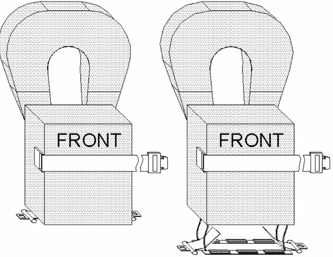
2. the number of spaces that can be provided on the seating arrangements in accordance with figure 4.1. The shapes may be overlapped as shown, provided footrests are fitted and there is sufficient room for legs and the vertical separation between the upper and lower seat is not less then 350mm.
Figure 4.1 Minimum seating arrangement according to SOLAS (Ref.[8]).
A review of the rules establishes however that there shouldn’t be a problem or contradiction to introduce additional systems to the lifeboats.
4.1.2 Models
Since the main concern revolved around the implementation of a new system in an already fixed environment it was necessary to get the facts straight. In order to make correct assumptions later on it was necessary to know more about the design and the inside geometry of lifeboats.
A couple of field trips down to the port cleared things up a bit. It was very enlightening to actually be on board the lifeboats. The first conclusion drawn from trip was that lifeboats exclusively seem to be constructed according to the SOLAS minimum requirements for the seating arrangements. It seemed that no space was left unused in them. For example, when the interior of a Waterman lifeboat, approved for 150 passengers, at M/S Silja Symphony was measured, it was hard at first to understand how it was possible that she could carry that amount of people. When it stood clear how the seating finally was supposed to work a quite claustrophobic feeling emerged. The Waterman is a partially enclosed lifeboat, which will be described more detailed further ahead.
Figure 4.2 Side and top view of a Waterman lifeboat.
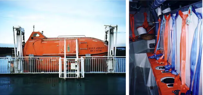
Another interesting lifeboat was the totally enclosed Norsafe on Finnlinks M/S Finnarrow. This particular type was perhaps not the most suiting one for this thesis but since it was newer and better equipped it gave a lot of ideas. For example, this type comes with safety belts so it was very informing to see the geometry and how they were constructed. Another thing was the seating padding, which certainly would increase the comfort and reduce impact forces.
Figure 4.3 and 4.4 The totally enclosed Norsafe on M/S Finnarrow. Note the seat belt
Partially enclosed lifeboats
This is a very common type of lifeboat, also in our waters. It comes in varying designs and sizes. There are quite a lot of manufactories on the present market. What differential the partially enclosed lifeboats are the permanently attached rigid covers they have over the stem and stern. The rules require that they have a length of at least a fifth of the total lifeboat length. The lifeboat should also be fitted with a foldable canopy, which together with the rigid covers should enclose the lifeboat. I.e. create a completely weatherproof shelter to protect the occupants on board for exposure.
Earlier it was much more common that people died from hypothermia in the lifeboats because they were open and gave no protection against the cold. Under SOLAS, lifeboats must be fully or partially enclosed. On passenger ships, partially enclosed lifeboats are used since they are easy to get into. The canopy should be highly visible, isolated and easy to erect. The lifeboats should have entrances on both sides, which easily and quickly could be opened and closed.
Besides the canopy, almost everything else is quite rigid on this type of boat, i.e. the surfaces inside are not constructed to absorb any forces or protect the occupants. The boats are usually made out of glass fibre or some kind of hard plastic. Because of the obvious skidding risk, surfaces like the seats and the paths are usually made a little rougher to increase the friction. Since almost all surfaces consist of straight parts without edges the lifeboat usually lack any kind of additional padding. The surfaces are so to say bare.
The most striking thing in a lifeboat is the logistics behind the seats. For obvious reasons are the occupants placed as tight as possible. The different arrangements were however quite similar. Compare the figures below; both lifeboats are approved for 150 occupants.
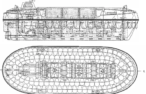
Figure 4.6 Side and top view of Greben PEL 150. Note that the occupants are seated in three
different levels. (Ref.[11]).
Figure 4.7 Seating arrangement in the Waterman lifeboat mentioned earlier. The seats in the
Figure 4.8 View from the inside of a Norsafe 10,8 M PELB. Note
that the heart shaped figures indicates the seating positions.
Because of the commonness of this type and the fact that they aren’t equipped with any additional safety appliances makes the partially enclosed lifeboat the main type for the further examination. Comparisons with the other types showed that they aren’t so suitable for changes. They will be introduced in the following sub chapters and show why that’s the case.
Self-righting partially enclosed lifeboats
The appearance of this type is quite similar to the partially enclosed lifeboat above. The major difference between them is how the stem and stern covers are constructed. In this case the covers forms two shelters separated with bulkheads. Access in to the covers is permitted by openings. The middle part of the lifeboat is constructed with a foldable canopy, which is operated in the same way as earlier. Since the enclosure permits the lifeboat to re-right after capsizes it is obvious that large motions could take place. The rules for this lifeboat require that safety belts should be fitted at each seating position in order to protect the occupants. The safety belt should be designed to hold a person weighing 100 kg safely secured in place during the evacuation.
Because of the fact that safety belts already are required and fitted in the self-righting partially enclosed lifeboat, this type wasn’t suitable to continue with. However, the type was not left completely, the fact that it neither has any rules or recommendation concerning the internal standard is still intriguing. The results shown for the partially enclosed lifeboat concerning this matter will probably be true here too.
Totally enclosed lifeboats
Every totally enclosed lifeboat are provided with a rigid watertight enclosure, which completely encloses the lifeboat. Access is only provided through hatches in order to keep the lifeboat completely watertight. Since the totally enclosed lifeboat (TELB) also are self-righting same rules as for the self-righting partially enclosed lifeboat applies here. For the same reasons are these concepts not compatible enough for a continued investigation. Another reason for the decision is the fact that they don’t carry as many people as the “ordinary” partially enclosed lifeboat in the same size does.
Figure 4.9 Norsafe 10,7 M TELB for 90 passengers.
Figure 4.10 Common seating
arrangement in the TELB’s
Figure 4.11 Safety belt arrangement on
the TELB. It usually consists of one buckle with two adjustment straps on the side.
Figure 4.12 Watertight hatch on the
TELB. Note the simplicity behind the
foldable rod that holds the safety belts over the hatch.
Free-fall lifeboats
The free-fall lifeboat is by the definition a type of the totally enclosed lifeboat. The regulations for the free-fall lifeboat are however much more specified in order to increase the protection for the occupants. Additional regulations concerning the seating environment and acceleration limitations are some examples on the material.
The free-fall lifeboats have more stringent rules for the seating arrangements. The main reason for that is the fact that the actual free-fall launch always looks about the same. Here it’s obvious that seats should be padded and provide a lateral support for head, torso and thigh. The width of the seat should be at least 430 mm. Free clearance in front of the backrest shall be at least 635 mm. The backrest should extend at least 1000 mm above the seat pan, in accordance with figure 4.13
F
Figure 4.13 Seating arrangement
In the free-fall lifeboats a recommendation is that you carry the lifejacket on board but don’t don it until the lifeboat has been launched. The reason for the recommendation is obvious, a lifejacket under the safety belt creates unnecessary slack over the body, which will worse the impact when the boat hits the water.
Figure 4.14 Norsafe GES 40 for 60 passengers. It’s approved to a maximal drop height of 30
4.1.3 Classification
The demands on the lifeboats on board ships are not always the same. It’s quite a difference between various ships. Different rules applies to different ships depending on what type of ship it’s supposed to be registered as. For example a passenger-ship are required to have a lifeboat-place for every person on board while the ferry only are required to have a rescue-place for every person on board. In reality that means place on a raft or at a lifeboat. It’s not necessary a bad thing to use rafts since they have proven to be about as safe as the lifeboats. A classification is performed by a classification-society and follows the international rules. IMO gives however the national shipping departments a great freedom of action in these matters. The national shipping departments are therefore quite free to adopt additional requirements. For good or for worse in some cases…
The class of the ship doesn’t say everything about the requirements for the lifeboats. The environment, i.e. the nautical conditions over the year, distance to shorelines and the location in general are also important factors in the decision for the required lifeboat. In Sweden the National Administration of Shipping and Navigation have declared five different speed-areas in order to deal with the environmental conditions (Ref.[14]).
The speed-areas are named A, B, C, D and E where A is the strictest one. The requirements for the safety appliances follow the rules stated by the speed-areas although exemptions also are made. The Administration considers both practical and
economical reasons in some cases.
Figure 4.15 and 4.16 Topmost the passenger ship M/S Carnival Triumph Courtesy and below
the ferry M/S Silja Serenade. Note the big difference in number of lifeboats. 3 lifeboats
4.2
Modulating the lifeboat
4.2.1 General
The main reason for the upcoming tests is to evaluate the different behaviour between fastened and unprotected occupants in a lifeboat. Since two cases were to be compared with each other, it was necessary to make a model in order to simulate the inside environment of a lifeboat.
Since unlimited funds or time weren’t available for the tests it was needed to make the model really efficient. It was necessary that the model would function irrespective of what kind of system it was supposed to simulate. I.e. it should be able to deal whit different kinds of lifeboat types, fastening systems and directions. For obvious reasons a couple of compromises were made in order to solve the logistic contradictions that came up.
4.2.2 Limitations
The initial ambition for the thesis was not only to evaluate the difference between fastened and unfastened occupants, but also to look further upon the different ways to fasten them. I.e. different safety belt configurations with two or four attachments were applied to the “systems” in order to evaluate the different performance between them.
See more details on the actual safety belts in chapter 5.2 Improvements on the lifejacket. Another addendum to consider here was how the different safety belt configurations would work in different kind of lifeboats.
A retrospect shows that there are quite big differences between the lifeboat types. For instance, in the partly enclosed lifeboat the seats are usually arranged in several levels and are without any back support. Not even the places close to the hull could counts, since the shape of the back usually is very uncomfortable. Because of the narrowness in the partly enclosed lifeboats it’s very difficult to make any additional installation. A four-point safety belt installation is therefore almost impossible to do because of the amount of space it requires. A complete rearrangement of the inside of the lifeboat isn’t a practical solution either; in that case it’s probably easier to consider another system, a two-point safety belt installation for instance.
With the exception from the partly enclosed lifeboat, the system with four-point safety belts still applies to all of the other lifeboat types. Recapture the figures from chapter 4.1.2; note that they all come with back support. It was also clear that it was necessary to take the four-point system under consideration.
It could be concluded that the minimum requirement for the model at least had to include one seat from each type.
4.2.3 Analysis of risks
In chapter 2.3 Motions and accelerations it was concluded that the most hazardous motions on the lifeboat was the lateral and vertical ones. Although that’s true the real analysis of risk must be performed inside the lifeboat with the individual seats in mind. Depending on how the inside of the lifeboat is arranged the individual seats aren’t equally safe. It was chosen to look further upon this matter with the Waterman PEL-150 discussed earlier in this chapter. Every other lifeboats of this type had probably been adequate too, since they are so similar in their construction.
Figure 4.17 Top view of the Waterman PEL-150. Note the seating arrangement and the
outlined section A-A. (Ref.[5]).
Section A-A above is representing approximately 80 % of the seats in the Waterman PEL-150. Since this arrangement is the indisputable most common one in the lifeboat it was chosen to look further upon that.
Figure 4.18 Section A-A in the Waterman PEL-150. Note the seating positions.
A study of the section above clearly supposes that the most exposed places are the ones close to the passageways. In the case with the lateral impact it is quite clear that occupants will fall on each other, especially dangerous are the “higher” falls from the upper bench down to the people below. The whole concept with long benches are also interesting to study since the passengers upon it will interact and contribute with different force on each other. I.e. an evaluation of the situation described in figure 4.18 would be useful, both for unfastened and fastened with a two-point arrangement.
Another similar arrangement would be the four-point solution for the more advanced lifeboats. A general section in such a lifeboat is shown below.
Figure 4.19 A common seating arrangement in lifeboats other than PELB’s.
The fact that they already are fastened in this situation makes the risk for collisions small. It’s nevertheless interesting to se how the occupants react to the motions that are going to be applied on them.
A summarise shows that it’s sufficient with one seat of each type for the upcoming tests. However one compromise had to be taken, instead of simulate the actual inside of hull for the partly enclosed lifeboat a settlement for a simpler solution was necessary. I.e. the same type of bench for both unfastened and the different fastened variants on those particular places was used. That compromise saved however much additional work since a simpler manufacture was possible. I.e. two instead of three benches were needed.
4.2.4 Benches
In the real lifeboat six occupants were seated next to each other. Unfortunately isn’t that possible to simulate in these tests. The testing equipment naturally determines the size of all tests. For instance, the crash-test sled is approximately 1.7 m width on the top, so it can’t allow much more space than for two occupants in width. The length on the crash-test sled is larger, but if two benches are to be fitted at the same time it still requires that non-of them are wider then two occupants. Even if the size of the crash-test sled had been larger it wouldn’t changed anything since the thesis were financially restricted in number of available dummies. This simplification does not change the overall behaviour of the interaction between seat and dummy. More of the test facilities are available in Chapter 6.
Figure 4.20 An Initial drawing of the benches.
The figure above shows the initial demands for the benches. The one on the right simulates the seats in the Waterman, or actually any lifeboat with seats in two levels. It wide and long enough to accommodate four people, the exact measurements are presented later and are regulated of SOLAS chapter III, Life-saving appliances and arrangements (Ref.[8]). The bench on the left is complete with back support and is supposed to simulate all types of lifeboats available. Even the partly enclosed one, although it’s a compromise.
The SOLAS rules apply to the bench with back support too, of course, but in this case some indefinite variables had to be decided. For instance, the design of back support gave us completely free hands. Since the wish was to optimise its protective performances, it was vital that the geometry was right. The problem was discussed with several professionals in this field, for instance Lars Hansson (Ref.[15]). After some discussion with Hansson, the conclusion was that the geometry of the back support very well could be straight and simple in its construction. It wasn’t necessary to make it curved, cupped or in any another way extraordinary. Since the impact times usually are very short for all tests, the most pressure is put to the fastening system. If the occupants are ergonomically and firmly fastened the shape of the backrest becomes less important.
The inclination angel are however a quite important value. Depending on how the impact hits the body different angels applies to different directions. In a lifeboat that is a problem since they usually are symmetric. I.e. what’s a good solution in one end is the complete opposite in the other. The inclination angel of the seat back has to be a compromise in this case. The conclusion was that an angel of exactly 10° would be appropriate here. It’s big enough to give the positive effect of an inclination but still small enough to feel natural to be seated in. A higher angel could perhaps be more ergonomic in some cases but it would probably also require some additional padding in order to do so.
Figure 4.21 and 4.22 Examples of a bench with back support (made in PTC Pro
DESKTOP®). Note that it is possible to install them transverse in the lifeboat. Since this was preliminary drawings the number of places isn’t accurate.
4.2.5 Manufacture
The actual making of the benches was arranged in co-operation with VTI. Drawings were supplied with the measurements and material specifications for the benches and they catered the actual production. See Appendix 1.4.
The intention for the benches was to make them easy to construct and rearrange on the platform and if possible also easy to fix if that should be the case. The intention of the benches was that they would behave more or less like real ones, i.e. the seat and backboard should allow some deflection. In order to fulfil all demands put upon the benches, the conclusion was to make them exclusively with thin-walled tubes and particleboard. With these structural members it was quite easy to fulfil the drawings exactly in the manufacturing. The tubes were to be welded together and form a frame that the particleboard then could be screwed on to. The particleboard is great to use because it’s easy to replace and allow some flexibility to the bench.
Figure 4.23 and 4.24 Some examples at the manufacture drawings made for VTI. Several
general and detail drawings were made in order to facilitate their work with the bench manufacture. All drawings were made in AutoCad®.
When the resistance for the benches was evaluated, stress calculation with FEM wasn't committed. Rather an engineering estimate was used to establish that the bench would last and behave correctly. It was known from the beginning that the magnitude of the violence in the collisions wasn’t unwieldy in this case. Since the external geometry of the benches already was given from the rules, the easiest way was to incorporate them with reasonable structural members. In this case it means thin walled 40x40x1.5 mm tubes and 14 mm particleboard of a tougher type. Since this concerned an actual production some openings were left for the shop, depending on their present situation. For instance, if they temporary were out of something specific, something similar would probably do the job as well.
Figure 4.25 The final measurements on the benches. The oval shaped dots indicates the
seatbelt attachments. (100 mm recess)
On the drawings presented to VTI considerations for the safety belts attachments were taken. The geometry behind the attachment is quite interesting. Since there are no rules postulated in SOLAS, the solution was by to apply the rules for motor vehicles on the benches instead. The motor vehicle rules are fascinating since they were postulated in the middle of the seventies and still applies (Ref.[13]). (EU directive 74/60) The rules are everything but detailed, for instance is the geometry regulations for the belts very generously drawn up.
It was concluded that the geometry for the safety belt attachments wouldn’t be a problem here, since almost free hands to incorporate the safety belts with the benches was given. After evaluation of the actual seating position with practical test, it was decided that the attachments should be mounted exactly 100 mm behind the frontal edge on the benches. It’s generally better to place the attachments as far back as possible, for preventive reasons, but in this case that was hard to fulfil because of the geometry.
The geometry rates the system but the actual handling of the safety belts had to come first here. The evaluations behind the attachment geometry were made with a theoretical lifejacket model in mind.
4.2.6 The final platform
The result of the finalised benches was very good. On the picture below are the manufactured benches placed on the crash-test sled. Note that there isn’t so much space up there. It would have been difficult to provide accurate safety for the dummies if the benches had been larger. In this case is it much easier to attain the safety since there still is space enough for guard-net installations. For further reading see chapter 6 Test facilities and test equipment.
Figure 4.27 and 4.28 Some additional photos. The work on the welded frames was very nice.
Note that the bottom is showing and that the bench attachments (to the crash-test sled) are visible.
5
Lifejackets and improvements
5.1
Present day lifejackets
5.1.1 Generally about lifejackets
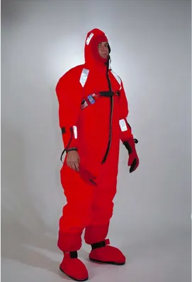
The lifejackets exists in different models and designs. All the way from the light vest used by the crews of leisure yachts to the more advanced models used by the military and crews on cargo ships. A more advanced item is the floating survival suit that is used mostly by the military, crews on commercial ships and offshore platforms. Survival suits are not usually used on passenger ships due to it is more costly and is not easily stored. They will not be a part of this thesis because it will be based on the devices used on passenger ships.
Lifejackets exists in two major design-concepts. They are separated by the way they float. One way is to use a material that has a lower density than water – buoyancy lifejacket (figure 5.1).
The other way is to use air inside the lifejacket to achieve floatability. These lifejackets are usually not filled with air all the time. Instead they are filled with air just before entering the water or even in the water – inflatable life jacket (figure 5.2).
Figure 5.1 Example of buoyancy
lifejacket. Taylortec Inc. Model LP-11
Figure 5.2 Example of an inflatable
lifejacket. Viking Life-Saving Equipment
It exists different main models of lifejackets such as the yoke (or over head) lifejacket (figure 5.3) and the vest type (figure 5.4).
Figure 5.3 Example of the yoke-type lifejacket
Figure 5.4 Example of the vest-type lifejacket.Regatta A/S Cruise
5.1.2 Some regulations concerning lifejackets
Lifejackets can be approved by different regulations such as the European Unions CE standard, but these lifejackets are only for leisure use. For commercial use the lifejackets are obliged to follow IMO’s regulations, i.e. SOLAS. These lifejackets are not intended to be used under normal activities, they shall save life in a emergency situation.
The rules for lifejackets are regulated by SOLAS chapter III and fulfils the IMO regulations A.689(17) (Ref.[8]) and A.520(13) (Ref.[16]). See also Appendix 1.1 Some of the most important rules are as follows:
A lifejacket shall be constructed so that
• After demonstration, a person can correctly don it within a period of one minute without assistance.
• It is capable of being worn inside out or is clearly capable of being worn in only one way and, as far as possible, cannot be donned incorrectly. • It is comfortable to wear.
• It allows the wearer to jump from a height of at least 4.5 m into the water without injury and without dislodging or damaging the lifejacket.
• It allows the person wearing it to swim a short distance and to board a survival craft.
• Its buoyancy is not reduced by more than 5% after 24 hours submersion in fresh water.
A lifejacket shall have sufficient buoyancy and stability in calm fresh water to: • Lift the mouth of an exhausted or unconscious person not less than 120
mm clear of the water with the body inclined backwards at an angle of not less than 20º and not more than 50º from the vertical position.
• Turn the body of an unconscious person in the water from any position to one where the mouth is clear of the water in not more than 5 s. (Figure 5.5-7)
Figure 5.5 and 5.6 Turning movement of an unconscious person. (Ref.[17]) Phase 1and 2.
Figure 5.7 Phase 3
The lifejacket shall also be fitted with whistle firmly secured by a cord and the lifejacket shall be made of clear colours and have reflectors to facilitate discovery. For all rules and tests concerning lifejacket see Appendix 1.1
The content of the rules is that a lifejacket must be, apart from logic function and good buoyancy, pretty robust and resistant from damage made by foreign objects.
5.1.3 Buoyancy lifejackets
The first buoyancy lifejackets were normally made of cork or kapok but nowadays they are normally made of different foams such as foam made by polyethylene.
The buoyancy lifejackets are normally cheaper and needs less maintenance than an inflatable lifejacket. These are the reasons why they are normally used on passenger ships and ferries. It’s not uncommon that the lifejackets are thrown overboard by intoxicated passengers (Ref.[5]).
They exist in two major designs – the vest type and the yoke type.
Two different major models exist for the yoke type, one with a large floating block and one without. The model without a large floating block is not as can be expected smaller than the model with. Instead it’s often the opposite. The block type model is popular in Baltic waters, while the non-block type are popular in North American waters. The yoke type lifejacket is equipped with a chest or waist strap and some are also equipped with one or two crotch straps. The crotch straps are used to avoid that the user falls through the lifejacket.
The vest type model is taken on at the same way as a jacket, while the yoke type is put over the head. The vest type lifejacket may have a crotch strap but the majority is not equipped with one.
A new type of buoyancy lifejacket has been developed in recent years. This type is a lifejacket, which protects the torso and head from heat loss. These so-called thermic lifejackets was developed after the M/S Estonia accident. The Norwegian maritime directorate Sjøfartsdirektoratet has prescribed the use of thermic lifejackets on Norwegian ferries and passenger ships. (Ref.[18])
The first version of the thermic lifejacket used commercially, Regatta A/S Thermo Cruise have been ordered (July 11 2002) to be modified because it doesn’t fulfil the regulations in SOLAS concerning the freeboard of the mouth and the angle of head towards the water. (Ref.[18])
![Figure 2.4 A complex problem is to predict the corresponding motion on the lifeboat under harsh conditions (Ref.[1])](https://thumb-eu.123doks.com/thumbv2/5dokorg/4770986.127294/12.892.96.780.121.486/figure-complex-problem-predict-corresponding-motion-lifeboat-conditions.webp)


![Figure 5.5 and 5.6 Turning movement of an unconscious person. (Ref.[17]) Phase 1and 2.](https://thumb-eu.123doks.com/thumbv2/5dokorg/4770986.127294/47.892.123.783.440.664/figure-turning-movement-unconscious-person-ref-phase-and.webp)