Lead-time reduction and rapid
prototyping of tools and fixtures,
therefore I AM
A case study about additive manufacturing in
the automotive industry
Master Thesis
Advanced level, 30 credits
Innovation and design, 120 credits
Christopher Gustafsson
Supervisor, Case Company: Fredric Eriksson
Supervisors, Mälardalens Högskola: Esko Mäkelä & Bengt Erik Gustafsson
Examiner: Yvonne Eriksson
Abstract
The purpose of this thesis is to investigate how to decrease lead-times of conventionally manufactured prototypes of tools and fixtures. Which could lead to increased knowledge of how an operations site within the automotive industry could utilize additive manufacturing when producing company specific prototypes of tools and fixtures. The research approach applied in this case study combines a literature review to systematically find relevant literature aligned with the research topic of additive manufacturing or 3D printing related to lead-time reduction and generative design terms. With the help of interviews and observations profound knowledge was gained as preparation before continuing the research. Thereafter, a pre-study was conducted in order to further enhance the understanding of the industrial context of the two chosen fixtures (study objects). Rapid prototyping activities with additive manufacturing processes and technologies of experimentation character was conducted iteratively with both 3D CAD and 3D printing software and hardware. Analysis of the data was conducted through a comparison between lead-times of conventionally manufactured and 3D printed prototypes of the two chosen fixtures. Moreover, identifying potential effects with additive manufacturing of prototypes have with a SWOT analysis. The case study found that additive manufacturing could significantly decrease lead-times when producing prototypes compared to conventional manufacturing. Furthermore, the results showed that the effects of additive manufacturing are plenty and rather complex due to the fact of this new way to manufacture prototypes. Therefore, the term design for additive manufacturing need first class priority if next steps were to be taken in the additive manufacturing field to enhance industrial and academic benefits.
The research on this subject is strongly constrained by the scarcity of empirical experience and, consequently, by the scarcity of available empirical data. Research publication on the topic are fruitful and plenty but their findings specified to their chosen study objects.
This case study gives an up-to-date contribution to the topic of additive manufacturing with endless possibilities to reduce lead-time with rapid prototyping activities that utilizes additive manufacturing. Moreover, the research approach used in this thesis combines 3D CAD data through theoretical concepts and physical objects with additive manufacturing practice. Overall, the results can be used to improve academic research in the topic and promote discussion among different actors entering or within the additive manufacturing field.
Sammanfattning
Syftet med examensarbetet är att undersöka hur ledtider kan minskas för konventionellt tillverkade prototyper av verktyg och fixturer. Detta kan leda till en ökad kunskap för hur en driftverksamhet inom fordonsindustrin kan utnyttja additiv tillverkning vid tillverkning av företagsspecifika verktyg och fixturer.
Den applicerade forskningsinriktningen i denna fallstudie kombinerade en literatur studie för att systematiskt finna relevant literatur inom forskningsämnet innehållande additiv tillverkning eller 3D printing relaterat till termer som reduktion av ledtid och generativ design. Med hjälp av intervjuer och observationer så har djupgående kunskap erhållits som förberedelse inför fortsatt forskning. Därefter utfördes en förstudie för att fortsätta öka förståelsen av den industrikontext som de två valda fixturerna (forskningsobjekten) erhåller i dagsläget. Rapid prototyping aktiviteter med additiva tillverkningsprocesser och teknologier utfördes iterativt som experiment med både 3D CAD och 3D printing mjukvara och hårdvara. Analys av data utfördes genom att jämföra ledtider av konventionellt tillverkade prototyper och 3D printade prototyper av de två valda fixturerna. Dessutom så kunde potentiella effekter med additiv tillverkning av prototyper identifieras med hjälp av en SWOT analys.
Fallstudien visade att additiv tillverkning kunde reducera ledtider signifikant vid tillverkning av prototyper jämfört med konventionell tillverkning. Dessutom så visades att det finns många effekter av additiv tillverkning med olika nivåer av komplexitet på grund av det faktum av detta nya sätt att tillverka prototyper. Därför behöver termen design för additiv tillverkning en förstaklassig prioritet om nästa steg ska tas inom det additiva tillverkningsfältet för att förbättra fördelarna för industrin och akademin.
Forskningen inom detta ämne är starkt begränsad av den bristande empiriska erfarenheten och som konsekvens uppstod brister med tillgänglig empiriska data. Forsknings publikationer inom ämnet är givande och många men att resultaten är bindande utifrån deras valda forskningsobject.
Fallstudien ger ett aktuellt bidrag till ämnet additiv tillverkning med oändliga möjligheter att reducera ledtid med rapid prototyping aktiviteter som använder additiv tillverkning. Dessutom så kombinerades 3D CAD data genom teoretiska concept och fysikaliska object med praktisk additiv tillverkning inom det valda tillvägagångssättet för denna typ av forskning. I överlag så kan resultaten användas för att förbättra akademisk forskning inom ämnet och främja diskussioner mellan olika aktörer som kliver in eller redan är inom området additiv tillverkning.
Preface
I would like to start this chapter by mentioning what a journey this have been and what an incredible opportunity it was to work co-productively with the industry when conducting research, simply amazing. Therefore, I must say that innovation and design cannot be relevant unless engineering is considered into the equation.
My interest for engineering technology has through the recent 10 or so years been exponentially escalating through new unseen heights. At first during my grade school days, engineering technology was almost unknown to my current knowledge at the time. After our first lesson in technology studies, in groups of two we built bridges with solid pasta and liquid glue, which was the very first time my interest for engineering took off. Several years later, we all graduated and I took my high school studies within nature science and engineering technology. There, I met amazing friends and acquaintances from all over town. We struggled our way through happiness and hardships through all three years until it was graduation time. There, I learned that engineering may be tough and rough around the edges but with a smile engineering could also become very fun. At this time I had to choose, whether to get a job or continue with higher education studies at the university. I chose to follow my gut feeling and became a student at Örebro universitet in the city of Örebro, and began my three year bachelor studies within industrial design and product development. During these three years I learned that engineering is something more than just equations and experimentation in school. In addition, I learned that a proper engineer is “someone who does precision guesswork based on unreliable data provided by those of questionable knowledge. See also the words wizard or magician.” Simply amazing description. During my studies, I met friends and acquaintances from all over the world. Once graduation was around the corner I had to decide what to do next, work or continue with even higher educational studies. I began working at the local University where I was educating fellow students to become engineers, a.k.a. wizards or magicians. After some time, nature took its course and I began studying higher educational studies for two more years, but this time I travelled to Mälardalens högskola in Eskilstuna. There, I studied the master’s program in innovation and design, and met some amazing friends and acquaintances from all over the world. I learned that engineering could be seem from a different perspective other than the hardcore technological stuff, but I always knew that engineering would be my forte. For two years we struggled through happiness and hardships, and my genuine love for engineering technology is an all-time high. One particular engineering technology that struck my interest was 3D printing, also known as additive manufacturing. Therefore, I decided to conduct my master thesis degree project together with a company in the Swedish automotive industry, which offered an opportunity to further conduct research in the additive manufacturing field. From our first meeting in December to the final moments in June, through happiness and hardships, it was simply amazing. Hereby, I would start to give my gratitude to my supervisor and all involved people during my master thesis at the collaborating case company, Fredric Eriksson, and Robby Kloos, to name a few of so many, for the thesis opportunity. I wish you all the best and continued success in life, and that my contribution to the team and the organization became fruitful for future endeavors. Thank you!
Next, I would like to give my gratitude to my supervisors at Mälardalens högskola, Esko Mäkelä and Bengt Erik Gustafsson, for fruitful contributions to the development of my master thesis. I wish you both all the best and continued success in life, and that my contribution to the team and the organization became fruitful for future endeavors. Thank you!
Furthermore, I would like to give my gratitude to my mentor at Örebro universitet, Nader Asnafi, for explicit and evident contributions to the development of my research and master thesis. I wish you all the best and continued success in life, and that my contribution to the team and the organization became fruitful for future endeavors. Thank you!
Most of all, I would like to give my outmost gratitude to my family, my mother – Jane Gustafsson, my father – Thomas Gustafsson, and all the others, for contributing to my wellbeing and my own personal development in life, and for supporting my decisions in life through happiness and hardships. I wish you all the best and continued success in life, and that my contribution to the team and the organization became fruitful for future endeavors. Thank you! Tack så mycket! Salamat! Puso!
To my fellow classmates, Amanda Hagman, Amani Othman, Andreea Strineholm, Athanasios Vatalis, Dare Gbenga, Christopher Akinboyewa, Imre Sabo, Koen Wijbrands, Minna Eronen, Tatiana Mihai, other fellow students, friends, acquaintances, and everyone in between that I had the privilege to meet and greet. Best wishes
Abbreviations
2D Two dimension
3D Three dimension
AM Additive manufacturing
CM Conventional manufacturing
CAD Computer-aided design
FDM Fused deposition modelling
h Hour
ISO The International Organization for Standardization
kg Kilogram
mm Millimeter
MPa Mega Pascal [106
∙ 𝑁 𝑚𝑚⁄ 2] N Newton [𝑘𝑔 ∙ 𝑚 𝑠2 ⁄ ] s Second stl Stereolithography
Terminology
3D printing A process of making three dimensional solid objects
from a digital file.
Additive manufacturing An appropriate name to describe the technologies that build 3D objects by adding layer-upon-layer of material.
Artifact An object made by a human being.
Conventional manufacturing Defined as a group of processes that remove excess material by various techniques involving mechanical, thermal, electrical or chemical energy or
combinations of these energies.
Development The process of developing or being developed.
Experiment A scientific procedure undertaken to make a
discovery, test a hypothesis, or demonstrate a known fact.
Fixture A piece of equipment which is fixed in a certain
position.
Generative design It is an iterative design process that mimic nature’s evolutionary approach to design which involves computer software to generate a number of outputs that meet certain rules and parameters.
Lattice structure A lattice is a pattern or structure made of strips of material which cross over each other diagonally.
Lead-time The time between the initiation and completion of a
production process.
Manufacturing The making of articles on a large scale using
machinery, and is also known as industrial production
Method A particular procedure for accomplishing or
approaching something.
Process A series of actions or steps taken in order to achieve
a particular end.
Production The action of making or manufacturing from
components or raw materials, or the process of being manufactured.
Prototype A first or preliminary version of an object from
which other forms are developed.
Rapid prototyping A group of techniques used to quickly fabricate a scale model of a physical part or assembly using 3D CAD data.
Technology The application of scientific knowledge for practical
purposes, especially in industry.
Tool A device or implement used to carry out a particular
function.
List of Figures
Figure 1: Relations between innovation, design, and engineering within the thesis (visualization by Christopher
Gustafsson which was adapted from Sannö, 2017) ... 4
Figure 1: The context and literature of interest in this research (visualization by Christopher Gustafsson) ... 7
Figure 2: Work process of fused deposition modelling (visualization by Christopher Gustafsson) ... 12
Figure 3: Work process of selective laser sintering (visualization by Christopher Gustafsson) ... 13
Figure 4: Generalized generative design process (visualization by Christopher Gustafsson) ... 14
Figure 5: Topology optimization example (visualization by Christopher Gustafsson), a) transparent CAD model with colorized components, b) rules and parameters applied to CAD model, c) generated design output ... 14
Figure 6: Lattice design example (visualization by Christopher Gustafsson), a) solid volume, b) 3D lattice unit, c) converted solid with 3D lattice structure, d) 2D lattice unit, e) converted solid with 2D lattice structure ... 15
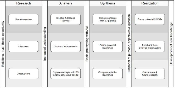
Figure 8: The innovation-design-engineering research process used in this research (visualization by Christopher Gustafsson) ... 18
Figure 9: The library research strategy (Ballenger, 2017)... 19
Figure 10: Abductive reasoning used in this thesis (visualization by Christopher Gustafsson which was adapted from Spens and Kovács, 2006) ... 20
Figure 11: The way of mixing qualitative and quantitative data in this thesis (visualization by Christopher Gustafsson which was adapted from Creswell, 2015)... 21
Figure 12: Selection criteria framework of potential study objects (visualization by Christopher Gustafsson) ... 22
Figure 13: The five-step approach to the literature review (Denyer and Tranfield, 2009) ... 24
Figure 14: Systematic review flow diagram (visualization by Christopher Gustafsson) ... 26
Figure 15: Prototyping process with plastic material used in the material extrusion process with the FDM machine (visualization by Christopher Gustafsson) ... 28
Figure 16: Prototyping process with metallic material using the powder bed fusion process with the SLS machine (visualization by Christopher Gustafsson) ... 28
Figure 17: SWOT analysis or SWOT matrix (visualization by Christopher Gustafsson which was adapted from Dess, 2018) ... 30
Figure 18: Abstract visualization of the case company organization (visualization by Christopher Gustafsson) . 34 Figure 19: CAD model representation of the palette (visualization by Christopher Gustafsson) ... 35
Figure 20: The chosen collection of components for defining Fixture A (visualization by Christopher Gustafsson) ... 36
Figure 21: The chosen collection of components for defining Fixture B (visualization by Christopher Gustafsson) ... 37
Figure 22: Process steps of Fixture A and Fixture B from when a problem had occurred till the problem was solved with the potential help of an external supplier – CM perspective (visualization by Christopher Gustafsson) ... 41
Figure 23: Process steps of Fixture A from when a problem had occurred till the problem was solved with the potential help of an internal supplier – CM perspective (visualization by Christopher Gustafsson) ... 42
Figure 24: Process steps of Fixture B from when a problem had occurred till the problem was solved with the potential help of an internal supplier – CM perspective (visualization by Christopher Gustafsson) ... 42
Figure 25: Visual comparison of Fixture A between a) the original design, and b) the simplified design with merged components (visualization by Christopher Gustafsson) ... 43
Figure 26: 3D printed prototype of Fixture A with the simplified design with merged components (visualization by Christopher Gustafsson) ... 44
Figure 27: 3D printed prototype of Fixture B with the original design (visualization by Christopher Gustafsson) ... 45
Figure 28: Application of topology optimization for Fixture A (visualization by Christopher Gustafsson), whereas a) visualizes the intended design space (purple area), support features (blue areas), and the applied force (red area), b) visualizes the parameterized design output from the topology optimization, c) presents finite element analysis results of maximum Von Mises stress, and d) presents finite element analysis results of maximum displacement ... 48
Figure 29: Application of topology optimization for Fixture B (visualization by Christopher Gustafsson), whereas a) visualizes the intended design space (purple area), support features (blue areas), and the applied force (red area), b) visualizes the parameterized design output from the topology optimization, c) presents finite element analysis results of maximum Von Mises stress, and d) presents finite element analysis results of maximum displacement ... 49
Figure 30: Application of a 3D lattice structure to certain solid parts of Fixture A (visualization by Christopher Gustafsson), a) the lattice structure unit, b) solid view of the dark grey solid body and the light grey lattice structure, and c) transparent view of the dark grey solid body and the light grey lattice structure ... 49 Figure 31: Application of a 3D lattice structure to certain solid parts of Fixture B (visualization by Christopher Gustafsson), a) the lattice structure unit, and b) Fixture B with the applied lattice structure unit ... 50 Figure 32: Removal of unnecessary volume with no feature or functional relevance from (visualization by Christopher Gustafsson), a) the simplified design of Fixture A, and b) to the new design of the simplified version of Fixture A ... 51 Figure 33: Application of a 2D lattice structure called honeycomb to (visualization by Christopher Gustafsson), a) the new design of Fixture A, and b) the original design of Fixture B ... 52 Figure 34: Process steps of Fixture A and Fixture B from when a problem had occurred till the problem was solved with the potential help of an external supplier – AM perspective (visualization by Christopher Gustafsson) ... 53 Figure 35: Process steps of Fixture A and Fixture B from when a problem had occurred till the problem was solved with the potential help of an internal supplier – AM perspective (visualization by Christopher Gustafsson) ... 54 Figure 36: Process steps of Fixture A and Fixture B from when a problem had occurred till the problem was solved without any supplier – AM perspective (visualization by Christopher Gustafsson) ... 54 Figure 37: Design changes of Fixture A, a) simplified design with merged components, b) topology optimization design, c) application of 3D lattice structure, d) new design of the simplified design, and e) application of honeycomb structure (2D lattice) (visualization by Christopher Gustafsson) ... 55 Figure 38: Design changes of Fixture B, a) original design, b) topology optimization design, c) application of 3D lattice structure, and d) application of honeycomb structure (2D lattice) (visualization by Christopher Gustafsson) ... 56
List of Tables
Table 1: Process steps of make goods lead-time, buy goods lead-time and other lead-time factors ... 8
Table 2: Description of line model components (Bartezzaghi, Spina and Verganti, 1994) ... 9
Table 3: Summarized classification of AM processes from literature that was used in this thesis project (Agarwala et al., 1996; Deckers et al., 2007; Dordlofva, Lindwall and Törlind, 2016; Gao et al., 2015; Gibson, 2017; Mohan, Venkata and Dhande, 2003; Noorani, 2006; Wong and Hernandez, 2012) ... 11
Table 4: Operationalization of the research topic ... 23
Table 5: Subject matter selection criteria ... 25
Table 6: Quality assessment criteria (Wong, Godsell and Skipworth, 2012) ... 25
Table 7: Calculation of the deviation between CM and AM with their supplier-driven lead-time and production-driven lead-time ... 31
Table 8: Numerical data of the palette ... 35
Table 9: Numerical data of Fixture A ... 36
Table 10: Numerical data of Fixture B ... 37
Table 11: 3D printing attributes of a potential 3D print in metal of Fixture A ... 44
Table 12: 3D printing factors of the 3D printed Fixture A ... 45
Table 13: 3D printing attributes of the 3D printed Fixture B ... 46
Table 14: 3D printing factors of the 3D printed Fixture B ... 47
Table 15: Comparison of lead-times of Fixture A with CM and AM excluding information/object transportation ... 57
Table 16: Comparison of lead-times of Fixture A with CM and AM including information/object transportation ... 58
Table 17: Comparison of lead-times between the various design changes to be 3D printed based on the design of Fixture A ... 59
Table 18: Comparison of lead-times of Fixture B with CM and AM excluding information/object transportation ... 60
Table 19: Comparison of lead-times of Fixture B with CM and AM including information/object transportation ... 60
Table 20: Comparison of lead-times between the various design changes to be 3D printed based on the design of Fixture B ... 61
Table 21: Overview comparison between Fixture A and Fixture B based on CM and AM processes ... 62
Table 22: Overview comparison between Fixture A and Fixture B based on design changes ... 63
Table 23: Summarized findings from the SWOT analysis ... 64
Table 24: Summarizing the fulfilment of the research objectives ... 70
Table 25: Various involved companies and organizations ... i
Table 26: Various involved people ... ii
Table 27: Continuation of various people involved ... iii
List of Equations
Equation 1 ... 9 Equation 2 ... 30
Table of Contents
1 Introduction ... 1
1.1 Background ... 1
1.2 Problem statement ... 2
1.3 Research purpose, research objectives and research question ... 3
1.4 Contributions to Innovation and Design ... 3
1.5 Scope and delimitations ... 4
1.5.1 Context-related ... 4
1.5.2 Theory-related ... 5
1.6 What was done prior to the thesis project ... 5
1.7 Thesis requirements ... 5
1.8 Thesis disposition ... 6
2 Theory ... 7
2.1 Introduction to the frame of reference ... 7
2.2 What is lead-time? ... 8 2.3 Additive manufacturing ... 10 2.3.1 3D printing processes ... 11 2.3.2 3D printing technologies ... 12 2.4 Generative design ... 13 2.4.1 Topology optimization ... 14 2.4.2 Lattice design ... 15 3 Research design ... 17 3.1 Research process... 17 3.2 Research approach ... 19 3.3 Research methods ... 21
3.4 Choice of study objects ... 22
3.5 Stakeholders ... 22
3.6 Operationalization ... 23
3.7 Pre-study ... 23
3.8 Data collection ... 24
3.8.1 Literature review ... 24
3.8.2 Semi-structured open-ended interviews ... 27
3.8.3 Semi-structured observations ... 27
3.8.4 Prototyping process ... 27
3.8.5 Experiment ... 28
3.9 Data analysis ... 29
3.9.1 3D printing test of prototypes ... 29
3.9.2 SWOT analysis ... 29
3.9.3 Comparison between CM and AM results ... 30
3.10 Research quality criteria ... 31
3.10.1 Research quality ... 31
3.10.2 Ethical considerations ... 32
4 The case study ... 33
4.1 Case company description ... 33
4.3 Case study objects ... 35
4.3.1 Tool – Palette ... 35
4.3.2 Fixture A ... 36
4.3.3 Fixture B ... 37
5 Results ... 39
5.1 Connecting the research topic with the results ... 39
5.2 Lead-times and process steps of conventional manufactured prototypes ... 40
5.3 Simplified design of the two fixtures ... 43
5.4 3D printed prototypes ... 43
5.5 Application of generative design ... 47
5.5.1 Application of topology optimization ... 47
5.5.2 Application of lattice structure ... 49
5.6 Lessons learned from additive manufacturing professionals ... 50
5.7 Lead-times and process steps of the 3D printed prototypes ... 52
6 Analysis ... 57
6.1 Comparison between CM and AM lead-times ... 57
6.1.1 Summarized comparison between Fixture A and Fixture B ... 61
6.2 Summarized findings from the SWOT analysis ... 63
7 Discussion ... 65
7.1 SWOT analysis with additive manufacturing ... 65
7.1.1 Strengths with additive manufacturing ... 65
7.1.2 Weaknesses with additive manufacturing ... 66
7.1.3 Opportunities with additive manufacturing ... 67
7.1.4 Threats with additive manufacturing ... 68
7.2 Fulfilment of the research question and research objectives ... 69
7.3 Knowledge development in innovation and design ... 71
7.4 Benefits for society ... 72
7.5 Research limitations of the selected research design ... 72
8 Conclusions and future research ... 73
8.1 Fulfilment of research purpose and conclusions ... 73
8.2 Suggestions for future research ... 73
8.3 Concluding remark ... 74
9 References ... 75 Appendix
1
Introduction
This chapter presents the background to the research and states the research gap, followed by the research purpose, research objectives and the formulated research question. Thereafter, contributions to innovation and design is discussed. Next, the scope and delimitations of the research is presented, followed by what was done prior to the thesis project at the collaborating case company. The chapter ends by presenting required knowledge to perform this type of thesis and the outline of the thesis.
1.1 Background
In recent years, several companies in the automotive industry have identified a need to change or even transform their current ways of working within manufacturing and production due to revolutionizing manufacturing trends such as additive manufacturing (AM). AM have been around since the early 1980s but in recent years, the manufacturing trend has become more common than ever before (Attaran, 2017; Gardan, 2015; Gibson, 2017). A vast majority of manufacturing and production companies worldwide has already begun exploring, applying and even implementing AM technologies with conventional manufacturing (CM). Specifically in Sweden, there have been several successes of various industrial cases in various materials such as polymers, ceramics, metals, wood and others (Agarwala et al., 1996; Gao et al., 2015; Nonino and Niaki, 2016). The most popular and most successful material to be fully implemented throughout industries is plastic materials but have major concerns regarding its effect on the environment (Gibson, 2017; Valdevit et al., 2008). The rise of metallic materials in industrial use are becoming more interesting for research and commercial use due to its industry benefits and material characteristics (Matos and Jacinto, 2019). With the changing tides of material science developments, this change will have a major impact affecting how we design products today and in the future (Valdevit et al., 2008).
This thesis seek to explore the possibilities of how AM affect lead-time during prototype production of tools and fixtures in hope of contributing new valuable knowledge with benefits to academia, industry, and society. The choice for industries to move into or apply their current business with AM is becoming more popular now than ever before. Why you might ask, well, one reason lies in its many benefits on improving production of low volume tools and fixtures with complex designs (Vimal et al., 2016; Klahn, Leutnecker and Meboldt, 2015), whilst another reason might be removing certain production waste, such as significantly high lead-times (Bartezzaghi, Spina and Verganti, 1994). These changes are important to consider, especially when designing tools and fixtures which needs to contain a design beneficial for AM. When a design change has been conducted and deemed useful, then it becomes an innovation beneficial for that company, and in the long-term, that particular industry. Industries are becoming more competitive and those with high end technology at their disposal have a competitive advantage over their competitors. In order for companies to become more competitive, several business components are critical to continuously improve on, but one will be the focus of this thesis, namely lead-time (Hayes and Wheelwright, 1984). One of several options for an enterprise to improve its manufacturing and production lies in the mysteries of AM (Candi and Beltagui, 2019). What does AM bring to the competitive industrial world? Well, the possibilities are endless so the only thing holding companies back is the current technological advancements and the willingness to embrace the relatively new technology.
From an engineering perspective, if societies can continue to maintain or increase its growth, radical technological innovations are needed, which has been seen through AM (Bandaly, Satir and Shanker, 2016; Gao et al., 2015; Tidd and Bessant, 2018). One thing to remember is that AM is not a replacement to current CM, but with the addition of AM combined with CM several academic, industrial, and societal benefits can be achieved (Gao et al., 2015; Gardan, 2015; Gartner and Maresch, 2018; Gasparre and Beltrametti, 2018; Gibson, 2017). For example, if a certain tool or fixture which contain several components, it may become possible to reduce the total amount of components by merging them together, which then could lead to the production of the ‘new’ tool or fixture within a single process (Gao et al., 2015; Gibson, 2017). This ‘new’ tool or fixture might be impossible to produce conventionally, but with AM this ‘new’ or rather complex design might be producible anyway (Attaran, 2017; Matos and Jacinto, 2019).
Dordlofva, Lindwall and Törlind (2016) argues the possibilities of introducing new optimized designs to tools, components and products on both part and assembly levels, whilst shorten lead-times to customers and reducing material costs. They also argue that AM create independence from expensive castings of CM but will be dependent on the complexity of the overall design on both part and assembly levels. Indications of how the design development can look like mirror itself through the concept of generative design (Gao et al., 2015; Gorguluarslan
1995; Thompson et al., 2016). Even though, the role of the designer plays a major part in the design process of optimizing for the greater good. From an academic perspective, Klahn, Leutnecker and Meboldt (2015) explains that it might be hard for the designer to take in all the possibilities of the design freedom that AM comes with, thus one challenge lies in identifying the ‘right’ components and assemblies with which AM can bring value all the way to the end user or customer (Vimal et al., 2016). Dordlofva, Lindwall and Törlind (2016) states a need for technology development in the AM field as the current processes and technologies only can do so much at the moment.
I think it is important to conduct research with the mindset of “do what you can’t” (Neistat, 2017), whilst striving for research results close to perfection. Especially when using AM, it is important to know that a majority of tools, fixtures, or products today could be produced with AM. However, it all comes down to whether the producer is willing to accept the cost and quality of the outcome even if the lead-time was reduced significantly. If the desired results was not reached after a first use or iteration using AM, the process could be easily utilized for more design iterations at relatively low cost depending on the circumstance. Additionally, if the tool, fixture, or product may have a complex design conventional production resources may be too expensive or time consuming, which in the case of AM may handle the production situation better. Therefore, this thesis embraces industrial rapid prototyping activities by applying AM and design change applications using generative design in order to investigate their effect on lead-time. However, it is important to remember that production or manufacturing perfection is not the right thing to strive for after one or few times of usage. Once the best practice of using AM has been instituted it would become a question of planning and execution for the desired outcome, and therefore, “never let perfect be the enemy of good enough” (Neistat, 2015).
1.2 Problem statement
According to researchers (see e.g. Gao et al., 2015; Gardan, 2015; Gartner and Maresch, 2018; Gasparre and Beltrametti, 2018; Gibson, 2017) and Swedish AM industry (see e.g. Stakeholder B, Stakeholder C, and Stakeholder D), they showcase a need for comprehensive technological development in the AM field. The new way to produce prototypes of tools and fixtures with AM is able to compete or de-throne CM depending on which situation AM is used and under which circumstances.
Today, one industrial need is to become faster from when an order is received until the final product has been delivered to the customer, which strongly relates to time, and more specifically lead-time. Therefore, a critical time within most industries, especially the case company, is the production lead-time to conventionally manufacture prototypes of tools and fixtures. The benefits of AM may be tough to generalize from one type of tool or fixture due to the various processes and technologies available in the AM industry, and therefore may depend from case to case.
Academic researchers (see e.g. Gao et al., 2015; Gardan, 2015; Gartner and Maresch, 2018; Gasparre and Beltrametti, 2018; Gibson, 2017) stress the need to uncovering ‘all’ mysteries of AM, even when resources and knowledge are strictly limited depending on the research case. They agree on one of several common grounds, namely that understanding evident data (e.g. dimensional accuracy, new manufacturing mindset, rapid production, etc.) of prototypes produced with AM are of outmost importance. Therefore, the practical problem is to tackle the outcomes from potentially using various AM processes and technologies in order to reduce lead-time of manufactured prototypes of tools and fixtures. Whereas, the theoretical problem is how to ensure lead-time is decreased after use of such processes and technologies.
To conduct research on the presented problem statements, a collaboration was setup with an operations site within the automotive industry (which was called ‘case company’ throughout the thesis), which was one of several stakeholders to support the case study research.
1.3 Research purpose, research objectives and research question
The purpose of this thesis is to investigate how to decrease lead-times of manufactured prototypes of tools and fixtures. This could lead to increased knowledge of how an operations site within the automotive industry could utilize AM when producing company specific prototypes of tools and fixtures. Whereas, the main objectives to develop a solid foundation for future decision-making were based on:
Identification of conventional manufacturing and additive manufacturing lead-times of the chosen fixtures
Comparison between conventional manufacturing and additive manufacturing with the means of producing prototypes rapidly of the chosen fixtures
Identification of strengths, weaknesses, opportunities, and threats with the application of additive manufacturing
In order to improve current production with a new technology requires a certain understanding of the potential AM possess, which was explored with the case study. Understanding this new way of work through exploration of the AM field within the automotive industry should help provide a potential direction for academic research and industrial success within the AM field.
In accordance with the thesis background, research purpose and research objectives, one research question was stated, namely:
RQ: What effect does additive manufacturing have on lead-times of conventional manufactured prototypes of tools and fixtures?
1.4 Contributions to Innovation and Design
The contributions of the thesis aims at providing new knowledge on how a relatively new field, such as AM, can be utilized by and provide industrial value to an operations site within the automotive industry. Therefore, such knowledge should be transparently analyzed and concretized in order to be relevant for other industries. Companies in the automotive industry are highly dependent on continuously improving to maintain a competitive advantage with their market peers. AM provides several strengths, weaknesses, opportunities, and threats to companies that are highly dependent on CM. Therefore, insights and lessons learned needed to be collected from specialists of companies and organizations already within the AM field. In order to use that knowledge of gained understanding to contribute with new knowledge to this new manufacturing field.
With the help of two fixtures as study objects, research with AM could gain relevance of using design to develop innovation. The study opted to utilize AM processes and technologies, as well as closely related terms of generative design as a means to explore the CM fixtures. The study would then signify the importance of utilizing technologies by means of exploring and experimenting with them to create something new, or gain new value. To clarify, a research through design approach could be used in order to develop a potential innovation. Whereas, design as a means of shaping or reshaping with the help of tools, technologies, and processes, to reach innovation as a means of new value, in terms of academic, industrial, and societal value (see Figure 1). Even though the thesis may seem to be engineering based and engineering focused, the means of creating innovation by design holds foundation within an engineering context based on my current background and main interest to the engineering field.
Figure 1: Relations between innovation, design, and engineering within the thesis (visualization by Christopher Gustafsson which was
adapted from Sannö, 2017)
1.5 Scope and delimitations
A thesis is easily affected by the researchers intent of wanting to ‘save the world’, but no one can manage it alone. Therefore, a context- and theory-related scope and delimitation was needed to constrain the case study, which will be presented in separate subheadings.
1.5.1 Context-related
To provide a clear description for the thesis content, the following list are context-related areas and activities that was studied, all in accordance with academic and industrial needs.
Specific academic researchers and industrial professionals from the Swedish AM industry was involved in order to gain more understanding of the research context of AM within the fields of innovation, design, and engineering.
Limited number of tools and fixtures, which are currently used at the case company, was identified with enough potential of generating new knowledge through AM. Therefore, two fixtures currently used at the case company was selected withholding the best potential for AM research. One of the two fixtures needed to contain a majority of plastic material, whilst the other needed to contain metallic material. Moreover, the chosen fixtures needed to contain several amount of components with a potential to be merged or excluded during design activities.
The used tools (computer software) was provided by stakeholders in order to: create 3D models from 2D drawings of the tool and fixture; create new 3D models for AM benefits through the use of conventional design and generative design means; generate quantitative data from the new 3D models; and prepare the new 3D models for AM means.
The 3D printed prototypes were used in order to perform design experiments in the sense of sharp tests in order to validate theoretical knowledge with practical means. Therefore, fulfilling the intended approach to research with the means of ‘learning by doing’ through ‘trial and error’.
1.5.2 Theory-related
To provide a clear description for the thesis content, the following list are theory-related areas and activities that was studied, all in accordance with academic and industrial needs.
The semi-structured open-ended interviews was connected with the help of an interview guide developed from operationalized research topic based on a comprehensive literature review.
It was accepted that only a limited number of tools and fixtures used at the case company with enough potential of generating new knowledge through AM was found. Therefore, the case study ended with just the two selected fixtures for further analysis and synthesis.
The two fixtures was chosen based subjectivity rather than objective reasoning, but considerations was made on the choice of study objects based on research relevance for the AM field.
It was accepted that the strengths and weaknesses of the used tools (computer software) in order to either simplify or enhance the conducted design processes.
Conceptual representations of the two fixtures were connected with practical means (design processes with software and hardware) in order to experience the means of ‘learning by doing’ through ‘trial and error’.
Research through design was used with the help of models, tools, processes, and technologies as a means of developing innovation with value for academia, industry, and society.
1.6 What was done prior to the thesis project
This thesis is seen as a continuation of further research based on the thesis project performed by Ragnartz and Staffanson (2018). They identified the problem statement of production complexity regarding replacement of tools and fixtures tend to apply high lead-times and high costs for remanufacturing with CM. Hence, their purpose was to see how the implementation of AM in the development process can reduce lead-time and cost of developing and manufacturing new components. Their aim was to construct an implementation plan for how AM can reduce manufacturing lead-time of fixtures, tools, and other production line equipment by 50% and reduce the cost by 20%, thus appointing a pair of hypotheses in need for validation. Moreover, they present the following two research questions, namely: what effects does implementing AM have on the development process for a large manufacturing company, and how can components for an automated manufacturing line be produced with AM in a cost-efficient way. Their main findings include that companies with no or little experience with AM will benefit mostly of purchasing a desktop 3D printer. Furthermore, their findings show that AM cannot be used in a cost-efficient way in manufacturing or development of metal components with a simple design, consequently due to high costs of such 3D printers and associated materials. Finally, they managed to identify the reduction of lead-time with 50% and costs with 30% of their appointed research study objects of production line work holders. Within the project, they managed to set-up a lab environment for desktop 3D printing with the purpose of enhancing the use of visual aids, educational models, presentation models, and functional prototypes. Final remarks, their concluded research results was set as the starting point for this thesis.
1.7 Thesis requirements
In order to be able to conduct a thesis project with a similar type of research topic, it is essential that the researcher has a solid understanding of the mechanical engineering field. In addition, since this engineering related thesis embraced innovation and design, the researcher is also required to have gained a solid understanding of the innovation and design field. I believe it is critical that the researcher knows the potential opportunity and risks related to a research topic that contain aspects from the innovation-design-engineering field.
1.8 Thesis disposition
The thesis consist of eight chapters and some content in the appendix. The content of each chapter is briefly presented in this subheading to give the reader an overview of the thesis structure.
The thesis starts with Chapter 1: Introduction. Here, the background to the research topic as well as the research gap are presented. This discussion leads on to the purpose and objective of the research, and the formulated research question. Thereafter, contributions to innovation and design is presented. Next, the scope and delimitations of the research is presented, followed by what was done prior to the thesis project at the collaborating case company. The chapter ends by presenting required knowledge to perform this type of thesis and the outline of the thesis.
In Chapter 2: Theory, a short background to the literature used within this research is presented as well as the link between the literature areas and the research context. Thereafter, lead-time is introduced and described based on understandings of CM, leading to the addition of AM processes and technologies.
Chapter 3: Research design explains the research design. First, beginning with an overview of the research process. Then, the research approach and research methods used is presented. Thereafter, the choice of study objects, involvement of stakeholders, and operationalization of the research topic was concluded before a pre-study was conducted. Moreover, data collection and data analysis was presented in terms of methods used and how the data was analyzed. The chapter ends with a presentation of the research quality as well as ethical considerations.
Chapter 4: The case study present the case study, beginning with a brief description of the collaborating case company. Thereafter, the case study positioning with the case company and other involved stakeholders are presented. The chapter ends with descriptions of the chosen study objects, namely Fixture A and Fixture B, as well as the palette tool.
In Chapter 5: Results, a connection is presented between the research topic and the results. Then, results regarding lead-time and process steps of Fixture A and Fixture B from a CM perspective are presented and discussed. Followed by a presentation of the simplified design outcomes of the two fixtures before presenting the 3D printed prototypes of the two fixtures. Moreover, application of topology optimization as well as lattice structure is presented in order to showcase further potential with AM. Thereafter, lessons learned from AM professionals are discussed. The chapter ends by presenting the lead-times and process steps of the 3D printed prototypes.
Chapter 6: Analysis presents the analysis of the results, and begins with the comparison between CM and AM results based on Fixture A and Fixture B. The chapter ends with a summarized presentation regarding the SWOT analysis.
Chapter 7: Discussion presents a discussion about the SWOT analysis with AM. Thereafter, a discussion is presented related to the fulfilment of the research question and research objectives. Moreover, the knowledge development in innovation and design, as well as the research benefits for society are then discussed. The chapter ends by discussing research limitations of the selected research design.
In the final Chapter 8: Conclusions and future research, the fulfilment of research purpose and conclusions drawn from previous analysis and discussion are presented. The chapter ends with suggestions for future research and concluding remarks of the conducted thesis.
2
Theory
This chapter starts by presenting a short introduction to the frame of reference, presenting the literature used in this case study as well as relating back to the research context. Thereafter, the lead-time used in this case study is described before introducing the relation between lead-time and AM. Then, AM processes and technologies used are presented. The chapter ends by presenting the connection between AM and generative design, as well as describing generative design terms used, namely lattice structure and topology optimization.
2.1 Introduction to the frame of reference
Relating back to the research purpose, and the stated research question and objectives, this research builds on the existing body of knowledge regarding lead-time reduction in general (see e.g. Bandaly, Satir and Shanker, 2016; Bartezzaghi, Spina and Verganti, 1994; Tersine and Hummingbird, 1995; Womack and Jones, 2003) with the application of AM in general (see e.g. Attaran, 2017; Matos and Jacinto, 2019; Gao et al., 2015; Gibson, 2017; Thompson et al., 2016) and generative design, specifically topology optimization and lattice structure (Ming, 2015; Junk et al., 2018; Walton and Moztarzadeh, 2017; Gorguluarslan et al., 2017; Hammetter et al., 2013; Valdevit et al., 2008) in order to rapidly produce prototypes (Nonino and Niaki, 2016; Noorani, 2006). Where literature in the areas of rapid prototyping, 3D printing, and generative design from the AM field have been used to investigate their effect on lead-time from a CM context. Figure 2 visualizes the current context at the case company with the goal to reduce their current lead-times of producing tools and fixtures to their main production, and with the addition of AM investigate the effects of such application.
Therefore, AM (or 3D printing) was used to study its effects compared to CM of prototypes of industry specific fixtures. Researchers have mentioned that a design change would be needed when entering a new manufacturing field. Therefore, generative design was used to study its effects on the two fixtures and see if it was beneficial in reducing lead-times during rapid prototyping activities with AM.
Figure 2: The context and literature of interest in this research (visualization by Christopher Gustafsson)
The rest of this chapter will present the concept of lead-time, as well as the used lead-times, namely production-driven lead-time and supplier-production-driven lead-time. This would then lead to the introduction of applying AM processes and technologies to rapidly produce prototypes. Lastly, when one has entered the AM field, one should consider the application of generative design as it potentially could further decrease lead-times.
2.2 What is lead-time?
Taking a closer look into any industry nowadays showcase their need to become better, stronger, and faster, which translates into considerations towards several important business components, one of them being lead-time. Since the thesis’ main focus is on lead-time, the possibility to completely exclude the other remain its difficulty. Several researchers and industrial practitioners mention that lead-time is the latency between the initiation and execution of a certain process, in which at the exact moment an order has been placed until the delivery at the final address has been made (Saravanan and Thakkar, 2018; Womack and Jones, 2003). Within supply chain management, lead-time is conventionally defined as the time from the moment the customer places an order (known as the moment the supplier learns of the order) to the moment it is ready for delivery (Bandaly, Satir and Shanker, 2016; Tersine and Hummingbird, 1995). In supply chain management those lead-times are known as manufacturing lead-time and information lead-time, which is described as supplier-driven lead-time (Saravanan and Thakkar, 2018; Turbide, 2009). From the perspective of manufacturing, lead-time carries the same definition as that of supply chain management, but includes the required time to transport the goods from the supplier, which is described as production driven lead-time (Tersine and Hummingbird, 1995; Turbide, 2009). Transportation time is included since the manufacturing company needs to know when the goods will be available for material requirements planning. In a manufacturing context those lead-times are known as make goods lead-times and buy goods lead-times. An abstraction of make goods lead-time and buy goods lead-time is visualized and described in Table 1 according to the understanding of lead-time literature (Bandaly, Satir and Shanker, 2016; Bartezzaghi, Spina and Verganti, 1994; Saravanan and Thakkar, 2018; Tersine and Hummingbird, 1995; Turbide, 2009).
Table 1: Process steps of make goods lead-time, buy goods lead-time and other lead-time factors
Make goods lead-time Buy goods lead-time Other factors to consider
Pre-processing lead-time – Time
required to create a work order from the time the requirement was learnt
Pre-processing lead-time – Time
required to create a purchase order from the time the requirement was learnt
Fixed lead-time – Time portion of
processing lead-time which is not dependent of order quantity Processing lead-time – Time required
to produce the goods
Processing lead-time – Time required
to purchase the goods
Variable lead-time – Time portion of
processing lead-time which is dependent of order quantity Post-processing lead-time – Time
required to make the goods available in inventory from the time it was received
Post-processing lead-time – Time
required to receive the purchased goods from the receiving dock to inventory
Total lead-time – Total time equal to
the fixed time plus variable lead-time multiplied by order quantity
Even though it may now seem clear enough of what lead-time actually is, the term is well adopted into many different concepts and situations. Bartezzaghi, Spina and Verganti (1994) connects time concepts and time-based competition into lead-time models of business processes, in which they identify the aggregate modelling of time into two classes, namely stage models and logical models. Stage models should be preferred when the process steadiness is high, consequently steady configuration allows the process to be engineered as a sequence of stages (Bartezzaghi, Spina and Verganti, 1994). Stage models can be useful for modelling the lead time of other less steady processes, e.g. new product development. Preferably, when dealing with radical technological change within a steady enterprise, such transition will not be steady, in fact, it will reek of uncertainty (Tidd and Bessant, 2018). Hence, the logical models are better aligned with unsteady processes, provided that they can be regarded as steady through a proper meta-process analysis (Bartezzaghi, Spina and Verganti, 1994). However, Thompson (1967) argues that when the real nature of an unsteady process is to be described, a problem-solving approach is more appropriate since the process of unsteadiness causes mutual instead of sequential interdependences. Bartezzaghi, Spina and Verganti (1994) propose one of two models as new concept adequate in explaining the making of the total lead-time in depth, which can effectively represent lead-time of any stockless process, and six components. A summarized component description of the line model is presented in Table 2.
Table 2: Description of line model components (Bartezzaghi, Spina and Verganti, 1994) Order Component Designation Description
1 Run time 𝑅 It is the sum of the net lapses during which the single object is actually processed. It
depends on the resource capacity and their specialization degree. Run time is computed as to the single object rather than the batch to which the object is possibly assigned. This way, run time concentrates on resource efficiency as a source of time and any other cause, whereas batch size for example is isolated in other time components.
2 Set-up time 𝑆𝑈 It relates to the set-up activities on the line, such activities which cannot be anticipated
simultaneously to the execution. Set-up time is therefore defined as the periods during which the object waits before being processed at any resources. It can be computed by referring to either the single object or the batch to which the object is possibly assigned.
3 Queue time 𝑄 It is the sum of the run times and the set-up times of the previous objects that a single
object might encounter when sent on to a resource. Note that the set-up time of the single object is not computed in its queue time.
4 Wait-to-Move time 𝑊𝑇𝑀 It is the time an object waits for the completion of either the transfer batch with which
it is forwarded to the next resource or the load batch which is necessary to start the processing. This component refers to both the elapsed time before moving to the next activity and the one from the last activity.
5 Synchro time 𝑆𝑌 It relates to the waits for synchronization between parallel phases of the process as it
depends on three causes, namely: waits for external inputs, waits for scheduled start time, and waits for control and coordinating mismatches. Synchro time is particularly relevant when the process is very complicated with a lot of parallel branches so that the management of the appointments becomes crucial.
6 Problem-solving time 𝑃𝑆 It showcase for the waits for non-routine decisions, while the repetitive ones can be
easily taken into consideration through the run time component. This component is distinguished from run time in order to describe better sudden and unstructured problem-solving activities.
With the definitions presented in Table 2, the composition law to generate the lead-time (𝐿𝑇𝑖) of an activity 𝑖 of a
process is the sum of all components shown in Equation 1.
Equation 1
𝐿𝑇𝑖= 𝑅𝑖+ 𝑆𝑈𝑖+ 𝑄𝑖+ 𝑊𝑇𝑀𝑖+ 𝑆𝑌𝑖+ 𝑃𝑆𝑖
The term lead-time itself could be rather theoretically complex, but when put into context it basically divides time into clusters which are defined according to the situational context it was put in. This was expertly presented by Bartezzaghi, Spina and Verganti (1994) several years ago, but how to use theory regarding lead-time could be quite simple depending on the research context. When conducting industrial research, several industrial practitioners state that “time is money”, and if research could provide sufficient solutions for reducing time, therefore, consequently, it could reduce money. One way to reduce time when producing prototypes would be with the help of a new manufacturing method, namely AM.
2.3 Additive manufacturing
Today’s society is bound by the many technological advancements such as the car, the smartphone, architectural buildings, coffee cups, sports equipment, books, and many more. All these have one major thing in common, they have all been developed and produced by us humans with various manufacturing and production methods, processes, tools etc. With the rise of Industry 4.0, a certain manufacturing technology is on the rise, and that is AM (ASTM standard F2792; Gardan, 2015; Gartner and Maresch, 2018; Wohlers Associates, 2019). The term rapid prototyping is strongly connected with AM as it possess the potential of rapidly producing prototypes with non- CM processes and technologies (Candi and Beltagui, 2019; Elverum and Welo, 2016; Gibson, 2017; Nonino and Niaki, 2016; Noorani, 2006). According to Wohlers Associates (2019), industries such as aerospace, medical/dental, automotive, and consumer products/electronics are the front runners with the AM technology (Gardan, 2015; Gasparre and Beltrametti, 2018; Gibson, 2017; Vimal et al., 2016). AM (also known as 3D printing) is a transformative approach to industrial production compared to CM, which enables the creation of lighter, stronger parts and systems (Attaran, 2017; Matos and Jacinto, 2019; Gao et al., 2015; Gibson, 2017; Thompson et al., 2016). Creating artifacts by adding materials layer-by-layer exploits the opportunity to ‘rapidly’ manufacture prototypes, components or parts with complex designs, and in some cases, reducing a hefty amount of originally used components by merging them into one large component (Gao et al., 2015; Gartner and Maresch, 2018). A potential opportunity of combining several components into one component or fewer components that could be nearly impossible to generate with CM (Gardan, 2015).
AM utilizes computer-aided design (CAD) software and specialized hardware, and at times 3D object scanners of digital objects that directs hardware to deposit material layer-by-layer into almost precise geometric shapes of physical objects (Attaran, 2017; Matos and Jacinto, 2019; Gao et al., 2015; Gibson, 2017; Thompson et al., 2016). In contrast to traditional manufacturing where it is often necessary to remove material (e.g. milling, cutting, carving, shaping, turning, drilling or other means), adding material to create components is one of the latest industrial trends as of date (Klahn, Leutnecker and Meboldt, 2015).
“Although the terms "3D printing" and "rapid prototyping" are casually used to discuss additive manufacturing, each process is actually a subset of additive manufacturing.” (GE
Additive, 2019)
Fast production of prototypes is not one of the strengths of CM. Therefore, Gao et al. (2015) presents a comparative overview between CM and AM of the unique capabilities that AM technologies contain, which are:
Design flexibility – Differential features of AM processes is the layer-by-layer approach, which enables the creation of most complex geometric shapes. Compared to the conventional way of subtractive processes, which constrain design freedom due to the need of fixtures, diverse tooling, and the possibility of collisions and difficulty in reaching ‘impossible to reach’ zones when manufacturing complex geometries.
Cost of geometric complexity – Current known AM technologies provide a vast variety of design freedom in order to realize complex geometric shapes. The complexity comes with no additional cost, no additional tooling, no re-fixturing, no increase in operator expertise, no extra fabrication time, etc. Dimensional accuracy – This relates to the print tolerance, which determines the deviation of the finished
model when compared to the original digital model. Research and industry highlight a need for establishing industrial dimensional accuracy standards for AM which resembles current dimensional tolerances and machining allowances based on the ISO and US standards for quality assurance.
Need for assemblage – AM processes enable production of geometric shapes that would require assembly of multiple parts when produced conventionally. Additionally, it is possible to produce single part assemblies that feature integrated mechanisms, whereas the parts and joints are printed in place and are suspended by support material which must be removed with post-processing methods.
Time and cost efficiency in production run – Some conventional processes are very time and cost efficient for mass production, regardless of high start-up cost, whilst AM processes are significantly slower and better suitable for low quantities. Moreover, on-demand and on-location AM production can lower inventory costs and potentially reduce costs associated with supply chain and delivery.
Researchers and industrial practitioners are continuously conducting research regarding 3D printing attributes of AM processes. Gao et al. (2015) reviewed attributes of printing a 3D object that are significant when considering selecting an appropriate AM technology and a corresponding build layout. They list along with factors such as machine selection, processes and materials, orientation and position of the geometry, and finishing that can alter the resulting quality of the printed part. The list contain as follows:
Build time – The build time for a model or an assembly depends on printer printing speed, part size, layer thickness, and build orientation regardless of the printing processes.
Feature resolution – Feature resolution is primarily dependent on the energy or material patterning principle and will vary depending on the specific AM process.
Surface quality – Generally speaking, the surface quality of a printed part is mainly determined by the thickness of each printed layer, in which the more curvatures the model contain higher probability of occurred build error.
Anchor and support material – Such means as anchors and support material are needed to create complex geometries such as overhangs, undercuts, and printed part assemblies with moving components. Post-processing – Printed objects with built-in support material require post-processing operations that
separate them, in which such removal methods vary depending on the printing method and build materials.
2.3.1 3D printing processes
This subheading begins with an overview of the selected 3D printing processes, namely the material extrusion and powder bed fusion processes, and are further presented in the subheadings.
In January 2012, the ASTM International Committee F42 on AM Technologies approved a list of several AM process categories with names and definitions, and in this thesis, one of those processes was used, namely material extrusion, and powder bed fusion was presented for potential use (Wohlers Associates, 2019). A summarized classification of the AM processes are listed and described in Table 3 according to the understanding of the literature.
Table 3: Summarized classification of AM processes from literature that was used in this thesis project (Agarwala et al., 1996; Deckers et
al., 2007; Dordlofva, Lindwall and Törlind, 2016; Gao et al., 2015; Gibson, 2017; Mohan, Venkata and Dhande, 2003; Noorani, 2006; Wong and Hernandez, 2012)
Categories Technologies Materials Power source Strengths & Weaknesses
Material extrusion
Fused Deposition Modeling (FDM)
Thermoplastics Thermal energy Inexpensive extrusion
machine
Multi-material printing Limited part resolution Poor surface finish Powder bed
fusion
Selective Laser Sintering (SLS)
Atomized metal powder
High-powered laser beam
High accuracy and details Fully dense parts High specific strength and
stiffness
Powder handling and recycling
Material extrusion
The material extrusion process was developed by Scott Crump in 1988, whereas the process creates layers by mechanically extruding molten thermoplastic material onto a build plate (Mohan, Venkata and Dhande, 2003). The method was later trademarked as Fused Deposition Modelling (FDM), which requires high operating temperatures, and consequently, the finished prints typically exhibit high porosity (Agarwala et al., 1996). However, the process is one of the most popular ones, whereas one common application is for desktop 3D printers (Gao et al., 2015). All material extrusion build materials include the classic thermoplastics, ceramic slurries, and as of late metal pastes, in which all utilizes thermal energy.
Powder bed fusion
Powder bed fusion is the process that use a thermal energy source to selectively induce fusion between powder particles inside a build area to create a solid object (Gao et al., 2015). Once a layer is scanned, the next layer of powder is then spread with a rolling mechanism. The subsequent layer is thereafter scanned, and is fused to the previous layer, whereas this process continues until finished, whereas resulting in the final component being encased in the metal powder. Powder bed fusion utilizes polymers, ceramics and metal powders as print material (Deckers et al., 2007). This process was initially developed by Deckard and Beaman in the mid-1980s but was further developed in 1995 and became commercially available since 2005 by EOS GmbH and Arcam AB respectively (Gao et al., 2015). One of the currently available technologies that uses powder bed fusion is selective laser sintering (SLS).
2.3.2 3D printing technologies
This subheading present the used technology of fused deposition modelling and the potential use of selective laser sintering.
Fused Deposition Modelling
A fused deposition modelling technology example is visualized in Figure 3 which is based on the material extrusion process. Once the spools of thermoset material is loaded into the printer and the digital instructions are programmed (also known as a sliced CAD model). The material is then extruded through a pipe until it goes through a high temperature nozzle that extrudes the heated material onto the build plate. With the help of a second extrusion nozzle, support material is extruded onto the build plate to support the building of part geometry. The extrusion nozzle continuous to move horizontally. After a layer is created, an elevator system shifts the build platform down, and the extrusion nozzle builds another layer of material. The process is repeated layer-by-layer until the build is complete.


![Table 7: Calculation of the deviation between CM and AM with their supplier-driven lead-time and production-driven lead-time Lead-times including/excluding information/object transportation CM (a) [h] AM (b) [h] Deviations (](https://thumb-eu.123doks.com/thumbv2/5dokorg/4731217.125186/44.892.108.798.133.420/calculation-deviation-production-including-excluding-information-transportation-deviations.webp)


