ISRN UTH-INGUTB-EX-M-2018/09-SE
Examensarbete 15 hp
Juni 2018
Design Automation of a Vacuum
Chamber
Creating Rules for Configurator
Besam Ahmed
Teknisk- naturvetenskaplig fakultet UTH-enheten Besöksadress: Ångströmlaboratoriet Lägerhyddsvägen 1 Hus 4, Plan 0 Postadress: Box 536 751 21 Uppsala Telefon: 018 – 471 30 03 Telefax: 018 – 471 30 00 Hemsida: http://www.teknat.uu.se/student
Abstract
Design Automation of a Vacuum Chamber
Besam Ahmed
The report is a degree project for the bachelor’s level in Mechanical Engineering at Uppsala University. The thesis was carried out at Scienta Omicron AB in Uppsala, Sweden and it is provided a basis determining rules for a vacuum chamber configurator that will be used by Scienta Omicron AB.
Scienta Omicron AB wants to automate its vacuum chamber design to increase company productivity and profitability within this product line. This degree project describes a basis for a configurator that will be used by the company later.
This degree project begins by interviewing Scienta Omicron's R&D manager and the Design Team to understand the company's needs and the reasons behind the desire to change the company's current process. After discussion with the company, a project plan for the thesis is established to ensure that all parts of the thesis are performed in time with good quality.
The report presents briefly the theory of vacuum technology, especially regarding ultra-high vacuum that is used by Scienta Omicron and several methods are used to achieve the project. The report ends with recommendations for Scienta Omicron with the intention of continuously improving the result of this thesis i.e. implementing the new process.
An intensive study of vacuum chambers manufactured by the company is carried out by reviewing the company’s email conversation between the design department and customers as well as chamber drawings in order to understand the design concept and its limitations.
As a part of the project, a requirement specification of the thesis has been determined and concept generating performed, resulting in two concepts,” clash models” and” matrix”. These enable the design and implementation of a vacuum chamber configurator by an external company specializing in customer product configuration.
The chosen concept is clash models because it facilitates the implementation of the configurator later. A third-party company, Animech, which will implement the rules determined in this thesis when constructing the configurator which will be used by SOAB. The configurator will be a tool that replaces the design team and gives them time resources to develop new solutions and products.
Keywords: Configurator Price Quote (CPQ), Clash Model, Matrix, Design Automation
ISRN UTH-INGUTB-EX-M-2018/09-SE Examinator: Matias Urenda-Moris Ämnesgranskare: Lars Degerman Handledare: John Åhlund
Sammanfattning
Rapporten är ett examensarbete i maskinteknik vid Uppsala universitet. Avhandlingen genomfördes på Scienta Omicron AB i Uppsala, Sverige och det är ett underlag för en
vakuumkammarkonfigurator som kommer att användas av Scienta Omicron AB .
Scienta Omicron AB vill automatisera dess vakuumkammar design för att öka företagets
produktivitet och lönsamhet inom produktsegmentet kammare. Detta examensarbete beskriver ett underlag för en konfigurator som kommer att användas av företaget senare.
Arbetet börjar med att intervjua Scienta Omicrons utvecklingsschef samt designteamet för att kunna förstå företagets behov och anledningar till att byta företagets nuvarande process. En projektplan för arbetet fastställs, efter discussion med företaget, för att säkerställa att alla delar av arbetet utförs i tid och med god kvalitet.
En intensiv studie om vakuumkammare tillverkade av företaget utförs genom att få tillgång till företaget datasystem för att kunna läsa mail mellan designavdelningen och slutkund samt att kunna gå igenom kammarritningar på levererade produkter, vilket bidrar till att förstå
kammarkonstruktionens begränsningar.
En kravspec av arbetet utformas och konceptgenerering resulterar i två koncept, ”clash modeller” och ”matris”. Kravspecen är ett underlag som används för att implementera vakuumkammarens konfigurator av en tredje part, ett företag inom IT. Koncepten som examensarbetet har kommit på testas och utvärderas och resultatet sammanställs i en slutrapport. Analysen av båda koncepten visar fördelar och nackdelar för varje koncept och diskuterar avgörande skäl för vilket av de två koncepten som väljas.
Konceptvalet är clash modellerna tack vare att den underlättar att konfiguratorn implementeras. Konfiguratorn ska vara ett verktyg som ersättar designteamet totalt, vilket bidrar till att företaget kan utnyttja den tiden till att ta fram nya lösningar och produkter.
Acknowledgment
I would like to thank all those who helped me during the thesis and the report writing, especially God. Then I would like to thank my supervisor at Scienta Omicron, John Åhlund, who played an important role in this project. I also thank Scienta Omicron's fine designers, Klas Backlund and Björn Schwerdtfeger, for their continuous support during the thesis in order to succeed in the project and also Pål Palmgren, Senior Scientist R&D at the company, for his constructive feedback.
In addition, I am also grateful for this support of my supervisor, Lars Degerman, at the Ångström Laboratory at Uppsala University who offered many comments and tips that added more value to the project.
Finally, I thank my beloved wife Alaa Zangana and beloved sister Muna Ahmed for encouraging me to study the engineering program and during all years of study.
Uppsala, May, 2018 Besam Ahmed
Table of Contents
1. Introduction ... 1
1.1 Background and Task Description ... 1
1.2 Goal ... 3 1.3 Delimitations ... 1 1.4 Requirement Specifications ... 1 2. Method ... 6 2.1 Literature Study ... 6 2.2 Interview Study ... 6
2.2.1 Qualitative Data Analysis ... 6
2.2.2 Qualitative Research Interview ... 6
2.3 Quantitative Research Study ... 7
2.4 Concept Generation ... 7
2.5 CAD modeling ... 7
2.6 Rule Tool ... 7
2.7 SWOT Analysis ... 8
3. Theory ... 9
3.1 Chamber Design Criteria ... 9
3.1.1 Photoelectron spectroscopy ... 9
3.1.2 Vacuum ... 10
3.2 Design Automation ... 16
3.2.1 Configurator Price Quote (CPQ) ... 17
3.2.2 Modularization of the chamber flanges ... 17
3.3 Mathematical Applications ... 18
3.3.1 Calculation of opening angle of the ports located in the chamber vessel 19 3.3.2 Calculation of distance between two ports located in a cylindrical geometry ... 20
3.3.3 Calculation of distance between two ports located in a spherical part of the chamber ... 21
3.4 Correlation between variables ... 23
3.5 Gross Margin ... 23
4 Current Process ... 24
4.1 Current Process Map ... 24
4.2.1 Important factors in the vacuum chamber design ... 25
4.2.2 How the vacuum chamber is designed today at SOAB ... 27
4.2.3 Difficulties facing vacuum chamber design ... 28
4.2.4 Number of Emails per chamber for the current process ... 28
4.2.5 Lead time per chamber for the current process ... 28
4.2.6 Difficulties facing the current process ... 28
5 Numerical Vacuum Chamber Rules... 31
5.1 Choice of the vacuum chamber shape ... 31
5.2 Choice of the ports number per chamber ... 31
5.3 Choice of the type of flanges for the chamber ... 32
6 New Process ... 34
6.1 New Process Map ... 34
6.2 Expected difficulties and risks facing the new process ... 35
6.3 Effects of the new process ... 35
6.3.1 Number of Emails per chamber using the new process ... 35
6.3.2 Lead time per chamber for the new process ... 36
6.3.3 Gross margin of the new process ... 36
7 Concepts ... 37
7.1 Clash Models ... 37
7.2 Matrix ... 39
8 Choice of Concept ... 42
9 Conclusions and Reflections ... 44
10 Recommendations ... 46 11 References ... 47 11.1 Books ... 47 11.2 Interviews ... 47 11.3 Workshop ... 47 11.4 Websites ... 47
Index of Figures
Figure 1: A complete (Ultra High Vacuum) UHV system for photoelectron spectroscopy applications designed and manufactured by SOAB where the vacuum chamber is highlighted in yellow color. The vacuum system consists of many parts such as, pumps and gauges that are coupled with the vacuum
system main body. (SOAB, 2018) ... 1
Figure 2: A vacuum chamber designed and manufactured by SOAB where this thesis will only focus on it. ... 2
Figure 3: The final product of the configurable vacuum chamber contained of basic modules and variant modules. ... 3
Figure 4: The three steps of qualitative data analysis. ... 6
Figure 5: Aa typical example of a PES setup. The analytical chamber is a central part of the system in where the analyzer, light source etc. is connected along with other types of equipment for sample preparation, vacuum pumping and monitoring etc. All parts needed for a PES setup is attached to the chamber via ports. PES needs ports for analyzer, light source, manipulator that holds the test sample. ... 9
Figure 6: Different degrees of vacuum. Selection of vacuum level depends on the application. The higher the vacuum, the less molecules in the chamber. ... 10
Figure 7: Aa turbo pump used to evacuate the vacuum system. The turbo pump is placed in a 150CF flange. (SOAB, 2018) ... 11
Figure 8: An ion pump used by SOAB to evacuate the vacuum system. (SOAB, 2018) ... 12
Figure 9: An ion gauge, placed in 40CF port, used in UHV system. Ionization vacuum gauges / hot cathode gauges is usually used to measure in the UHV range 10-3 to 10-10 Torr. (SOAB, 2018). ... 12
Figure 10: Different shape of the vacuum chamber to prove why SOAB normally uses the round vacuum chamber. ... 13
Figure 11: two bell shaped vacuum chambers that have different thickness in order to prove why SOAB uses the round chamber with 3mm thick. ... 14
Figure 12: A vacuum chamber manufactured by SOAB. On the chamber, some types of ports below the vacuum chamber are seen and used to connect other parts of the vacuum system. ... 15
Figure 13: An example of how the ports sometimes intersect with others when the chamber is designed according to the customer port list sent by emails to SOAB design team. ... 19
Figure 14: A vacuum chamber that the main body, consists of two different shapes (parts), and a port tube with a flange. This figure used to illustrate how the opening angle of ports is calculated. ... 20
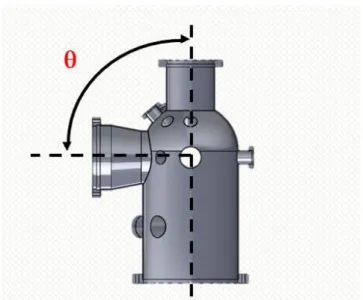
Figure 15: The angel (theta) between the ports and the cylindrical body of the vacuum chamber. .... 20
Figure 16: Two ports located on the main body of the vacuum chamber. This figure used to illustrate how the distance between these ports is calculated depending on the angle between them. ... 21
Figure 17: The distance between two ports located on the vacuum chamber. ... 22
Figure 18: SOAB current process of the vacuum chamber. ... 24
Figure 19:The important factors of a successful vacuum chamber design. ... 26
Figure 20:Ishikawa-diagram illustrates the causes behind difficulties facing the current process. ... 29
Figure 21:A configurable vacuum chamber which will be used as a standard chamber when the configurator will be implemented. ... 31
Figure 22: Some chamber body properties determined in this thesis. ... 32
Figure 23:Properties of each port that will be used to configure the vacuum chamber. ... 32
Figure 24: Different types to choose variable values such as drop-down, free values and choice between two variables. ... 33
Figure 26: The new process will be devised after the project is completed. ... 34 Figure 27: The clash models of ports. Different clash models depend on different type ports located on the vacuum chamber. ... 37 Figure 28: How the clash models of each port is calculated by using the opening angle equation. .... 38 Figure 29: The clash model of 150CF pump and the small ball behind the model is used to mate the clash model with the pump port. ... 39 Figure 30: a part of the matrix made during the thesis that used to suggest for user the position of the ports in phi and theta angles and shows an example of if-function used to locate the port NW40CF and the manipulator 150CF. ... 39 Figure 31: A part of the matrix and illustrates an example of if-function used to locate the port NW40CF between the ports 200CF and 150CF. ... 40
Index of Tables
Table 1: the benefits and problems of design automation. ... 16 Table 2: the benefits of using CPQ. ... 17 Table 3: the four important factors that have to be discussed to choose one of the two concepts. ... 42
1
1. Introduction
1.1 Background and Task Description
Scienta Omicron AB1 (SOAB) is a leading innovator company in Surface Science. SOAB designs
about 15 vacuum chambers per year. The chambers are now designed by human interaction between the design department at the company and the end customer. Each chamber is currently unique, but the company wants to switch to modularization of its chambers by standardization of ports and flanges, which are parts of the chamber's vacuum system, to reduce variant choices, which result in shorter lead times and simplify the design process for the end customer. A modularization will support high quality choices and prevent customers from making design proposals that lower the quality of the products. To reduce the number of design-hours for each chamber and have a
configurable chamber, SOAB needs to change the chamber sale/design/manufacturing process and go to a process using a customer interactive configurator which allows the users to design their own chambers by choosing between different types of ports etc. The aim of this thesis, is to determine which parts can be configured with each other by creating rules for all the parts that are included in the end product. This thesis focuses on the design of analytical chambers for photoelectron
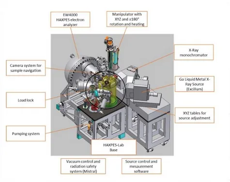
spectroscopy. Figure 1 shows one of the vacuum systems, used for photoelectron spectroscopy, manufactured and assembled by SOAB. This thesis will focus on the design process of the vacuum chamber, shown in Figure 2, with emphasis of generating of a tool such that this chamber can be configured without aid of manual design.
Figure 1: A complete (Ultra High Vacuum) UHV system for photoelectron spectroscopy applications designed and manufactured by SOAB where the vacuum chamber is highlighted in yellow color. The vacuum system consists of many parts such as, pumps and gauges that are coupled with the vacuum system main body. (SOAB, 2018)
Examensarbete: Design Automation of a Vacuum Chamber
2
Figure 2: A vacuum chamber designed and manufactured by SOAB where this thesis will only focus on it.
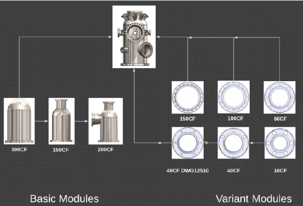
Besides the main chamber body, the vacuum chamber consists of a single or double liner that is placed inside the chamber. These liners ensure a high level of magnetic field shielding, which is required not to disturb the measurement. The customer can choose between double or single liner depending on the demand of the application. These liners are not discussed in detail to protect the intellectual property (IP)2 of SOAB. At the top in Figure 3, the final product is seen. To the left in the figure, the main body and the other main ports are placed on it. All the chambers that will be
manufactured, contain these three ports. To the right of the figure, there are the selectable flanges from which the customer can choose several flanges of the same type, or a variety of different types according to rules and limitations set up in this thesis. The purpose of these rules is to restrict the customer in such a way that SOAB is able to create a configurable vacuum chamber as well as to maintain the performance inside the chamber.
Figure 3: The final product of the configurable vacuum chamber contained of basic modules and variant modules.
2 "Cultural Heritage & New Media - The John Marshall Institutional ...."
Capital 1, Introduction
3
1.2 Goal
The goal of this thesis has been set by SOAB in order to fulfill the requirements discussed in Section 1.4. This study aims to:
1) Map out the current process of chamber design and manufacturing used by SOAB.
2) Propose a new process in which a configurator is used by the customer and sales team to design the chambers. The goal of the new process is to:
• Reduce the time from order to manufacturing, and then production will benefit from that all orders will have a standard form, i.e. the material is standardized.
• Enable the order to be delivered with good quality.
• Allow Sales to leave a design proposal that can be manufactured without having to wait for feedback from the SOAB design team.
• Allow SOAB to approximate a price of the vacuum chamber, in which leads to cost control.
• Allow SOAB to meet and improve delivery time requirements. • Make communication between the customers and sales more efficient.
3) State the rules for the configurator such that the configurator can be implemented by a sub-contractor.
4) Compare the two processes in terms of cost.
5) See how a configurator can be profitable for SME3,Small and Medium-sized Enterprises, compared to large companies.
1.3 Delimitations
This thesis will focus on generating an excel file which includes new rules that can help to
automate the design of the vacuum chamber. The hypotheses are that the configurator will reduce design hours and enable working with sub-contractors. The lead times can be shortened if the choices are limited in such a way that the sub-contractors can stock or pre-fab parts of the vacuum chambers.
1.4 Requirement Specifications
1. Determine, via a case study, if the profitability4, by using a product configurator, can be increased compared to manual design for SME type of companies.
2. Is it possible to align product profitability with the industry average?
3 "Små och medelstora företag – Wikipedia."
https://sv.wikipedia.org/wiki/Sm%C3%A5_och_medelstora_f%C3%B6retag. Opened 8 May. 2018.
4 The profitability of the current manufacturing process is not aligned with the industry average for manufacturing
Examensarbete: Design Automation of a Vacuum Chamber
4 3. The case study will be performed at SOAB focusing on one of the products of their
customized product segment, i.e. a double lined stainless-steel analysis chambers for Angle-resolved photoemission spectroscopy (ARPES)5 , given that the manufacturing methods used today that are kept.
This thesis will investigate:
1. Technical feasibilityof designing a product configurator for this product. This investigation will address the following:
1.1 Define limits and prerequisites for the manufacturing process and how the design of a chamber and rules are to be defined.
1.2 Where is constraint based, sequentially programmed based (“if then else”) or relation based (Matrix) logic for the specific product applied.
2. Potential direct and indirect profitability gains by implementing a new process from sales through design, to manufacturing using a product configurator.
3. Reflect on other benefits and risks of implementing a product configurator.
5 "Angle-resolved photoemission spectroscopy of the cup rate ...." 27 Aug. 2002, https://arxiv.org/abs/cond-mat/0208504.
6
2. Method
2.1 Literature Study
A literature study will be carried out at the beginning of this project to understand the field of
vacuum- and surface science in general and the specific needs for electron spectroscopy applications in particular, in order to understand the underlying design constraints. The literature study will also focus on the Configurator Price Quote (CPQ), which SOAB aim to implement, using the
configurator tool.
2.2
Interview Study
In order to form a proposal on how the new process should look like; the designers will be interviewed regarding problems that arise in the current process and the reasons behind these problems.
2.2.1 Qualitative Data Analysis
Qualitative data analysis follows three basic steps6, see Figure 4:
Figure 4: The three steps of qualitative data analysis.
• Preparing and organizing data including transcribing interview notes, observations and all needed documents which are gathered during the thesis.
• Reducing data into themes by identifying the important themes needed to the research and creating categories for each theme.
• Presenting data in narrative or graphic form to have a conclusion of the research. 2.2.2 Qualitative Research Interview
The purpose of the interview is to explore related persons' views on factors that increase design hours per chamber and why the company wants to switch the current process into a new process that goes with an interactive configurator. Interviews, as one of the qualitative methods7, contribute to increase understanding of problems. This thesis focuses only on core issues without having to engage
6 "Methods of data collection in qualitative ...." 22 mars. 2008, https://www.nature.com/articles/bdj.2008.192. Opened 5
May. 2018.
7 "Qualitative research - Wikipedia." https://en.wikipedia.org/wiki/Qualitative_research. Opened 7 June. 2018.
Preparing and organizing data
Reducing data into themes
Presenting data in narrative or
graphic form
Examensarbete: Design Automation of a Vacuum Chamber
7 in other less important factors that take time without achieving the goal of the thesis. Individual Interview is an appropriate method for having more detailed insights from different employees, who have different responsibilities in the same area, as the company's production manager and design department, which consists of two designers.
2.3 Quantitative Research Study
Quantitative research study is another method that depends on the statistic study to identify a problem (need) by accessing data collections and using this data to come up with solutions to solve the problem8. This method is used in this thesis by having access to SOAB’s data system in order to
read the archived emails between the company and its customers and also to study the drawings of the previous vacuum chambers, about 60 chambers. This is to understand the reasons behind why SOAB has a long communication with the customers and have more details on the chamber design, for example, the max and min angles of ports, the length of ports, positions of these ports and what type of chambers which can be configurable and what are the components which are suitable to be standardized. In addition, the data collection helps to study the correlation between important variables in the current process, for example, the correlation between the number of emails and the chamber’s complexity, the number of ports per chamber, the correlation between the number of revisions and the chamber’s complexity and also the correlation between the number of emails and the time spent to each chamber.
2.4 Concept Generation
The thesis needs to come up with concepts which are easier to implement and to use. In addition, it needs to find out how the rules should be formulated in a manner that may be clear and useful for the third-party company that will implement the configurator (Animech)9.
2.5 CAD modeling
In order to create rules for the new process, a vacuum chamber will be designed in Solidworks10 (SW), based on existing drawings provided by SOAB. Design time, manufacturing cost and lead time should be studied to enable comparison between the new and the old design methods. SW is used to test different solution proposals and to understand the functionality behind the chamber design. SW is also used to compare different shapes of the vacuum chamber by testing their pressure resistance to prove why SOAB normally uses a round shape of the chamber, as well as to test two vacuum chambers that have different thickness to prove why the company uses 3mm thick walls for its chambers.
2.6 Rule Tool
Excel will be the tool used to create the design chamber rules. These rules are used to limit the number of possible cases, allowing automated chamber design by the configurator, and will be in the form of tables, photos, and comments which will guide Animech to implement the configurator. For each port will all needed information about length, angle, and the name be given. In addition, these
8 "Quantitative research - Wikipedia." https://en.wikipedia.org/wiki/Quantitative_research. Opened 19 May. 2018. 9 "Animech | Home." https://animech.com/. Opened 19 May. 2018.
Capital 2, Method
8 rules will explain which of parameters that will be treated as constants or variables depending on the type of port and its functionality11.
2.7 SWOT Analysis
SWOT analysis12 is a planning tools that is used to find strengths, weaknesses, opportunities and threats of concepts in a strategic review. This method used to analyze the two concepts, which are generated in this thesis, in order to facilitate the choice of one of these concepts. SWOT analysis helps to analyze the strengths, weakness of potential concepts and it is also to analyze the
opportunities and threats of concepts in which can help to select one of the thesis' two concepts, which is easier at implementing and using by the sale team and the customers. SWOT analyzing is more overall method than other methods to analyze the thesis' concepts because of this method analyzes all effect sides of each concept and does not just mention somethings with an assessment of the numbers. For this reason, SWOT analysis is used in this thesis to select the best solution. see chap. 8.
11 "Microsoft - Official Home Page." https://www.microsoft.com/sv-se. Opened 7 June. 2018.
12 "SWOT-analys - SVID." http://www.svid.se/sv/Designprojektguiden/1-Forberedelse/Verksamheten/SWOT-analys/.
9
3. Theory
3.1 Chamber Design Criteria
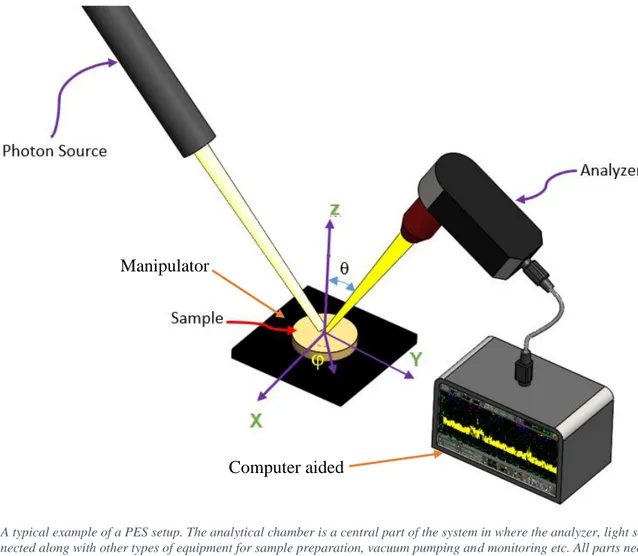
This chapter discusses the purpose of the chamber in a photoelectron spectroscopy experiment, the role of vacuum for the experiment and a short description of a vacuum in general, see Figure 5.
Figure 5: A typical example of a PES setup. The analytical chamber is a central part of the system in where the analyzer, light source etc. is connected along with other types of equipment for sample preparation, vacuum pumping and monitoring etc. All parts needed for a PES setup is attached to the chamber via ports. PES needs ports for analyzer, light source, manipulator that holds the test sample13.
3.1.1 Photoelectron spectroscopy
Photoelectron spectroscopy (PES) is a method to analyze the electronic structure of atoms molecules and solid materials. A schematic image of a PES setup is seen in Figure 5. It consists of a photon source, a sample on a manipulator, a photoelectron analyzer and computer aided control and
diagnostics. The source, sample and analyzer are mounted on a chamber that holds the vacuum of the setup. PES is a surface sensitive technique that can determine the chemical composition of materials, and hence it is important to keep the surface of the sample clean. PES has further needs of:
1) The analyzer is constructed out of electrostatic lenses that require a vacuum not to discharge.
13 "X-ray Photoelectron Spectroscopy - Electra Synchrotron Trieste." 4 Oct. 2012,
https://www.elettra.trieste.it/lightsources/labs-and-services/surface-lab/x-ray-photoelectron-spectroscopy.html. Opened 8 June. 2018.
Manipulator
Examensarbete: Design Automation of a Vacuum Chamber
10 2) The light that is used to emit the electrons from the sample is absorbed in air.
3) The mean free path of electrons is not sufficiently long in environments of high pressure for most PES setups to function.
For these reasons a chamber that holds vacuum is needed. 3.1.2 Vacuum
Although the vacuum pump was invented in 1650, it took 300 years to produce better vacuum conditions than 10-7 Torr14, which is a unit of pressure used in the vacuum technology beside the Pascal unit and equal (1.3*10-5 Pa). The word ‘vacuum' comes from Latin ‘vacua' which means ‘empty'. In a vacuum, air and/or other gases have been removed from a volume with the help of equipment called vacuum pumps. A vacuum is produced by reducing the number of molecules within a certain space relative to its surroundings. To reach UHV conditions requires a highly specialized pumping system and a chamber which has low outgassing characteristics15.
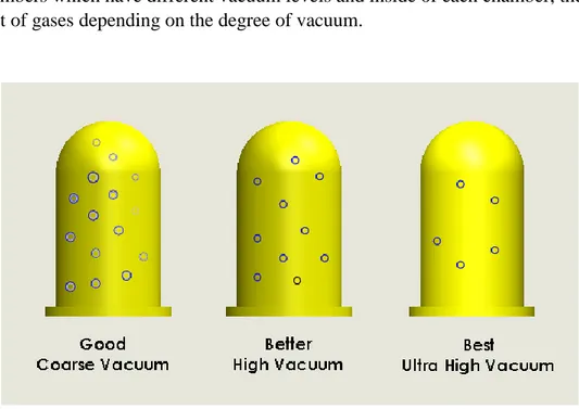
In vacuum technology, there are three vacuum degrees (ultra-high vacuum, high vacuum and coarse vacuum) and choosing the degree of vacuum depends on applications, see Figure 6. This figure shows three chambers which have different vacuum levels and inside of each chamber, there are different amount of gases depending on the degree of vacuum.
Figure 6: Different degrees of vacuum. Selection of vacuum level depends on the application. The higher the vacuum, the less molecules in the chamber.
This thesis focuses on designing chambers for UHV applications, UHV is the only vacuum
classification used by SOAB in order to deliver a chamber fulfilling the customers’ requirements,
UHV is defined by a pressure <10-8 Torr16 (1.3*10-6 Pa). UHV systems are used in space-,
materials-, physics research, surface science and metallurgy. A Vacuum environment is used when an area needs to be very clean, in other words, it should be free from gases which could affect an
14 Heide, P. (2012).
15 Grunderna i tillämpad Vakuumteknik, page16, Svenska Vakuum Sällskapet.
Capital 3, Theory
11 experiment. Inside the UHV chamber, the mean free path, the average distance traveled by a moving molecule of gas, is 1 km - 105 km17.
Choosing a suitable vacuum pump depends on application. Some of the pumps have the ability to remove the gases from the chamber, other can catch these gases or change its forms to a solid phase. However, no pump can reduce the number of molecules in gas phase to zero in the chamber18. For the type of chamber studied in this thesis it is common to include a Turbomolecular pump, which is linked to a roughing pump. In parallel, an Ion pump that contains a titanium sublimation pump (TSP) is fitted to the vacuum chamber. The turbo pump is usually attached to the chamber via a 150 CF flange and the ion pump is usually attached below the chamber on a 150 CF flange. The
turbomolecular pump is used to obtain and maintain UHV. This type of pump works on the principle that gas molecules is given momentum in a determined direction where the molecules collide
frequently with the solid surface of the rotating blades of the pump19, see Figure 7.
Figure 7: Aa turbo pump used to evacuate the vacuum system. The turbo pump is placed in a 150CF flange. (SOAB, 2018)
The roughing pump evacuates the vacuum system to about 1x10⁻³ Torr (0.13Pa)20. This type is also called pre-vacuum pump and is used to lower the pressure on the exhaust side of the turbomolecular pump.
The function of the TSP is to evaporate Titanium on surrounding surfaces which then chemically reacts with the gas molecules in the chamber. This reaction removes the gas molecules from the vacuum system. The TSP can only be started if there is a sufficient vacuum in the chamber21, see Figure 8.
17 "Mean free path - Wikipedia." https://en.wikipedia.org/wiki/Mean_free_path. Opened 5 apr.. 2018.
18 Grunderna i tillämpad Vakuumteknik, page 40,Svenska Vakuum Sällskapet.
19 Grunderna i tillämpad Vakuumteknik, page 77,Svenska Vakuum Sällskapet.
20 Grunderna i tillämpad Vakuumteknik, page 42,Svenska Vakuum Sällskapet.
Examensarbete: Design Automation of a Vacuum Chamber
12
Figure 8: An ion pump used by SOAB to evacuate the vacuum system. (SOAB, 2018)
An Ion pump consists of two titanium cathodes and an anode. This pump operates in a manner where a magnetic field forces the free electrons to move in long helical paths rather than in straight lines. This operation leads to increase the probability that the electrons will collide with molecules on the path to the positively charged anode. In this way, the probability of ionization increases and thus the amount of useful work which the pump can perform can be increased22.
A pressure reader is an important part of a vacuum system as its function is to measure the status inside the vacuum chamber and quality of the vacuum. Depending on which pressure range is to be monitored different readers are used, such as bourdon gauge, thermocouple gauge, ionization and cold vacuum gauge23. A UHV vacuum chamber is typically equipped with an ion vacuum gauge, see Figure 9, usually mounted on a 40CF flange.
Figure 9: An ion gauge, placed in 40CF port, used in UHV system. Ionization vacuum gauges / hot cathode gauges is usually used to measure in the UHV range 10-3 to 10-10 Torr. (SOAB, 2018).
22 Grunderna i tillämpad Vakuumteknik, page 86,Svenska Vakuum Sällskapet.
23 Grunderna i tillämpad Vakuumteknik, page 104,Svenska Vakuum Sällskapet.
ION PUMP
Capital 3, Theory
13 There are important design factors for UHV chambers, such as the pressure difference between the outside and the inside of the chamber. The pressure that acts on the outer walls of the chamber is approximately 1 bar, therefore, the chamber must be designed in a way that it can withstand this pressure difference without being deformed, and at the same time24, it must be able to have a base pressure of <10-10 Torr (1.3*10-8 Pa). In this section, two different shapes of vacuum chamber will be discussed to analyze why the cylinder shape is usually used to design the vacuum chamber, see Figure 10. In this figure, a cylindrical chamber and a square chamber are seen. For both chambers, a pressure of 1bar is applied on a wall of 3 mm thick. In case of the cylindrical chamber, the chamber is no deformed when it is applied to the pressure. In case of the square chamber, the chamber is plastically deformed at the sharp edges when it is subjected to pressure and that means it needs a thicker wall than the cylindrical chamber.
Figure 10: Different shape of the vacuum chamber to prove why SOAB normally uses the round vacuum chamber.
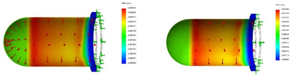
In this section, the thickness chosen for the vacuum chamber will be analyzed, see Figure 11. This figure shows two cylindrical chambers: to the left, a vacuum chamber with 3mm walls and to the right, a vacuum chamber with 1mm thickness. The figure illustrates the effect of pressure (1bar) on chambers material. The displacement of the vacuum chamber (3mm thick) when it is applied to the pressure is ( 0.005mm) while the displacement of the vacuum chamber (1mm thick) when it is applied to the same pressure is ( 0.014mm). There is no large difference between 1mm and 3mm regarding displacement. The main reason why the company chooses 3mm thick, is that the thickness of <3mm is difficult to manufacture in machines25. Choosing of a thicker vessel chamber than 3mm increases the material cost as well as leads to increase the weight of the chamber.
24 Grunderna i tillämpad Vakuumteknik, page 123,Svenska Vakuum Sällskapet.
Examensarbete: Design Automation of a Vacuum Chamber
14
Figure 11: two bell shaped vacuum chambers that have different thickness in order to prove why SOAB uses the round chamber with 3mm thick.
Materials used in the production of chambers must have many important properties26 such as: • High-temperature tolerance
• Similar thermal expansion coefficients • Low outgassing rates.
Materials used to manufacture the UHV chambers at SOAB are:
• Stainless steel SST is a good choice because of its high mechanical strength to handle the high-temperature variations, it can also handle the air pressure on the vacuum chamber. The advantages of SST are that it is not oxidized, therefore, it can be made with a smooth surface that does not give large areas for gases to adhere to and it is easy to weld27.
• Copper: Vacuum chambers are usually equipped with Oxygen-free copper28 (OFHC), which
is used as sealing ring or pipes for material being transported in and out of the chamber. This material also tolerates large temperature changes as well as it is a very good conductor of electricity and heat29.
• Ceramics are used in the vacuum chamber as an electric insulation30.
• Mu-metal is a nickel-iron alloy which is characterized by its high magnetic permeability. This high permeability makes mu-metal very effective for shielding static or low-frequency magnetic fields, which cannot be damped by other methods31.
System parts are coupled with flanges that allow the ability to build a large system in a modular manner. Flanges also provide the ability to quickly connect and disconnect system parts with the intention of controlling system operation. SOAB uses different types of flanges to build its system depending on what part is coupled with them32. All flanges used by SOAB have the designation NW (inner diameter) CF, for example, NW66CF. The NW33 is a German designation (Nennweite) that means nominal pipe size in U.S. standard and CF34 means conflat, see Figure 12. This figure shows
26 Grunderna i tillämpad Vakuumteknik, page 123,Svenska Vakuum Sällskapet.
27 Grunderna i tillämpad Vakuumteknik, page 124,Svenska Vakuum Sällskapet.
28 "Oxygen-free copper - Wikipedia." https://en.wikipedia.org/wiki/Oxygen-free_copper. Opened 23 May. 2018. 29 Ibid.
30 Ibid.
31 "Technical Data – Mu-METAL® Magnetic Shielding ASTM A753." http://www.mu-metal.com/technical-data.html.
opened 8 June. 2018.
32 Grunderna i tillämpad Vakuumteknik, page 127,Svenska Vakuum Sällskapet.
33 "Nominal Pipe Size - Wikipedia." https://en.wikipedia.org/wiki/Nominal_Pipe_Size. Opened 9 May. 2018. 34 "Kurt J. Lesker Company | KF (QF) Flange Technical Notes | Vacuum ...."
Capital 3, Theory
15 the vacuum chamber that is used as a configurable chamber by SOAB. The chamber consists of the main body, a set of ports and flanges that are welded onto it.
In addition to the stainless-steel chamber body, mu-metal liners are needed for high performance PES. The liners screen the earth magnetic field such that the experimental volume of the chamber close to the analyzer is reduced >1000 times i.e. the value close to 0.5-0.1 micro tesla). The need for reduction of the magnetic field is due to that the electrons are charged particles and charged particles alter their trajectories in magnetic fields. The consequence for a PES measurement of altered electron trajectories is distorted spectra and hence the measurement quality is substantially compromised. For this reason, one or two set of liners is incorporated into the chamber on the inside of the stainless-steel body35. The exact design and location of these liners are not presented in this thesis as this is regarded SO IP. However, the form factor of the liners affects the overall design criteria presented here.
Figure 12: A vacuum chamber manufactured by SOAB. On the chamber, some types of ports below the vacuum chamber are seen and used to connect other parts of the vacuum system.
35 Hollas, J. (1982),
Analyzer port
Pump port Ion gauge port
View ports
Manipulator port
Vacuum vessel ( flange 300CF) Photon Source port
Examensarbete: Design Automation of a Vacuum Chamber
16
3.2 Design Automation
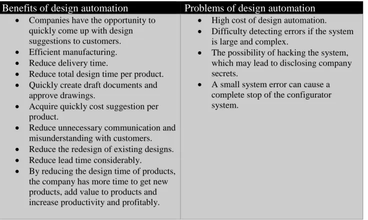
Design automation is a way that is used to design fast and easy, to standardize, modularize and parameterize design. Design automation helps to automatically create production and assembly the documents of the drawings for sales quote by using Configurator Price Quote (CPQ) tool36.Table 1 shows the benefits37 and the problems38 of design automation.
Table 1: The benefits and problems of design automation.
Benefits of design automation
Problems of design automation
• Companies have the opportunity to quickly come up with design suggestions to customers. • Efficient manufacturing. • Reduce delivery time.
• Reduce total design time per product. • Quickly create draft documents and
approve drawings.
• Acquire quickly cost suggestion per product.
• Reduce unnecessary communication and misunderstanding with customers. • Reduce the redesign of existing designs. • Reduce lead time considerably.
• By reducing the design time of products, the company has more time to get new products, add value to products and increase productivity and profitably.
• High cost of design automation.
• Difficulty detecting errors if the system is large and complex.
• The possibility of hacking the system, which may lead to disclosing company secrets.
• A small system error can cause a complete stop of the configurator system.
36 "What is Design Automation? - Drive Works." 25 Jan. 2018,
http://www.driveworks.co.uk/blog/what-is-design-automation/. Opened 29 Apr. 2018.
37 "Tacton." https://www.tacton.com/. Opened 29 Apr. 2018.
38 "The Complexity of Design Automation Problems - Semantic Scholar."
https://www.semanticscholar.org/paper/The-Complexity-of-Design-Automation-Problems-Sahni-Bhatt/1452f205b7161abf3bb8be61e825b11f59cd08d6. Opened 29 Apr. 2018.
Capital 3, Theory
17 3.2.1 Configurator Price Quote (CPQ)
Configure (C) means that one system can include many products and services, for example, the configurator used by Scania trucks39. The Price (P) used to calculate the cost, margin, etc. and Quote (Q) used to generate documents, drawings by efficiently management both for simple and complex quoting requirements. CPQ helps manufacturers design, sale made to deliver configurable products. CPQ is suitable for all types of companies, for example, industrial equipment, building products and even fashion. The benefits of using CPQ is discussed in Table 2 to illustrate why many companies today use it40.
Table 2: The benefits of using CPQ.
Benefits of CPQ
1) Suggested quickly a complete proposal to the customer.
2) Included a set of applications and services to get easier configurable products. 3) Auto-generated CAD-files.
4) Easy to select and configure complex products with a powerful and visually appealing experience.
5) Used variety of techniques to guide the user to right products by showing images, radio buttons and drop-down boxes.
6) Allowed to suppress and unsuppress feature options to protect company privacy. 7) Ability to configure price quote and order products.
8) Automatically assemble a variety of documents that the user needs to form a complete accurate proposal.
9) Reduced product cost regarding reduced lead time and design time.
10) Contributed to have less scrap and rework because the company receives correct manufacturing information the first time.
3.2.2 Modularization of the chamber flanges
Modularization is a way to create an end product that consists of a combination of basic modules and variant modules in a configurable manner. The purpose of modularization is to limit the number of variants and increase the number of possible end products. It leads to reduced manufacturing costs, as it requires fewer resources and less design time per product and can also lead to shortened delivery time. There are two common forms of modularization, the first one is qualitative
39 "Scania | Scania Sverige." https://www.scania.com/se/sv/home.html. Opened 19 May. 2018. 40 "What is Configure Price Quote Software (CPQ)? - Definition from ...."
Examensarbete: Design Automation of a Vacuum Chamber
18 modularization, modules have different characteristics and fill different functions., and the other form is quantitative modularization, the same modules have the same characteristics and are
combined to give a product the desired capacity, power etc.41. To modularize a product, the parts of the product needs to be divided into:
• Basic modules: The parts that always have to be included i.e. all chambers should contain these basic modules.
• Variant modules: The modules that the customers can choose from. In that case, there are six flange sizes that the customers can choose from to build the chamber.
• Customer Modules: Modules that are not included in the configurable product and normally are designed by the company’s design team with a special cost. In this case, the vacuum chamber is considered to be a special chamber, not a configurable chamber, which is handled outside the configurator.
3.3 Mathematical Applications
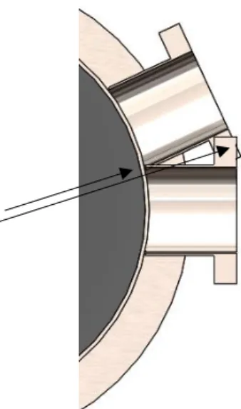
In this section, the mathematical equations are used to calculate the distance between the ports that are located both on the spherical and cylindrical parts of the vacuum chamber as well as to calculate the opening angle of the ports in order to calculate the corresponding angle to keep material (3mm) around these ports. These equations help to calculate the minimum distance between ports that should be kept to avoid the intersections between ports regardless if they are located on the cylindrical or the spherical shape of the chamber, see Figure 13. This figure shows a section of a vacuum chamber designed in this thesis. The figure shows two ports placed on the main body and intersect with others. The reason for this type of intersection is that the vacuum chamber is designed today according to the customer requirements, which are sent in a form of a port list that includes number of flanges, angles, positions, etc.
Capital 3, Theory
19
Figure 13: An example of how the ports sometimes intersect with others when the chamber is designed according to the customer port list sent by emails to SOAB design team.
3.3.1 Calculation of opening angle of the ports located in the chamber vessel The opening angle equation (1) used to calculate the angle (α) of each port located on a spherical geometry and also to calculate the angle needed to keep material between the ports to avoid the intersection between them. Here (r) is the radius of the chamber main body and (D1) is the outer
diameter of the port tube. Figure 14 illustrates how this equation is used to calculate the opening angle in order to calculate the corresponding angle should be to keep enough material around the ports to avoid intersection with others. This equation is also used to calculate the opening angle of the ports which are located in a cylindrical part of the chamber.
Examensarbete: Design Automation of a Vacuum Chamber
20
Figure 14: A vacuum chamber that the main body, consists of two different shapes (parts), and a port tube with a flange. This figure used to illustrate how the opening angle of ports is calculated.
The opening angle (α) = 𝟐 ∗ 𝒂𝒓𝒄𝒔𝒊𝒏 (𝑫𝟏
𝟐𝒓) ∗ 𝟏𝟖𝟎
𝝅 (1) 42
3.3.2 Calculation of distance between two ports located in a cylindrical geometry After the angle between them has been calculated (see Figure 15 & Figure 16). Equations (2 to 6) are used to calculate the distance between the ports located on a cylindrical part of the chamber,
Figure 15: The angel (theta) between the ports and the cylindrical body of the vacuum chamber.
42 "Spherical Trigonometry -- from Wolfram Math World." http://mathworld.wolfram.com/SphericalTrigonometry.html.
Opened21 May. 2018.
α D1
r
Port tube with flange
Spherical part of the chamber
Examensarbete: Design Automation of a Vacuum Chamber
21
Figure 16: Two ports located on the main body of the vacuum chamber. This figure used to illustrate how the distance between these ports is calculated depending on the angle between them.
• P1= diameter of port nr.1. • P2= diameter port nr.2.
• D= distance between P1 & P2 from the center of the ports. • M= distance between P1 & P2.
• r = radius of cylinder. 𝐃 = ∫ 𝒓𝒅𝝋 = 𝒓 [𝝋]𝟎𝝋 𝟎𝝋= 𝐫𝛗 (2)43 𝑫 = 𝒓𝝋 (3) 𝒎 = 𝑫 −𝒑𝟏 𝟐 − 𝒑𝟐 𝟐 (4) 𝒎 = 𝒓𝝋 −𝒑𝟏 𝟐 − 𝒑𝟐 𝟐 (5)
𝝋 =
𝒎+ 𝒑𝟏 𝟐+ 𝒑𝟐 𝟐 𝒓 (6)3.3.3 Calculation of distance between two ports located in a spherical part of the chamber
Equations (7 to 11) used to calculate the distance between the ports located on the spherical part of the chamber, see Figure 17. This figure shows two points represented two ports which are located on a spherical part. This figure is used to illustrate how the distance between these ports is calculated depending on the angle between them.
43 "Circle Line Picking -- from Wolfram Math World." http://mathworld.wolfram.com/CircleLinePicking.html. Opened
Capital 3, Theory
22
Figure 17: The distance between two ports located on the vacuum chamber.
• P1= diameter of port nr.1. • P2=diameter of port nr.2.
• d= distance between P1 & P2 from the center of the ports. • r = radius of cylinder.
• D= the arc between P1 & P2 represented the distance between these ports. • α= angle between ports.
P1(r,1,1)
P2(r, 2,2)
x= r cos cos y=r sin cos z= r sin
d= r*sqrt(2-2cos(1) cos(2) cos(1-2)-2sin(1) sin(2)) (7)44
α= 2arcsin
(
𝒅 𝟐𝒓)
(8) sin 𝜶 𝟐=
𝒅 𝟐 𝒓(9) 𝑫 = ∫ 𝒓𝒅α = 𝒓 [α]𝟎α α 𝟎 (10) D= αr (11)
44"calculus - What is the shortest distance between two 2D points on ...." 19 Oct. 2015,
https://math.stackexchange.com/questions/1488345/what-is-the-shortest-distance-between-two-2d-points-on-the-surface-of-a-cylinder. Opened 30 Apr. 2018.
P1
P2 D d
Examensarbete: Design Automation of a Vacuum Chamber
23
3.4 Correlation between variables
To understand the relationship between the number of emails per vacuum chamber and the time spends to achieve the chamber design, it needs to study the correlation45 between these variables by studying about 60 vacuum chambers manufactured earlier by SOAB. There are different ways to calculate the correlation between two variables, but in this thesis, the Pearson's product-moment coefficient46, the most well-known and most common form, is used where the correlation is
calculated as the covariance between the two variables divided by the standard deviation of the two variables
x, y=
𝑬(𝑿−𝝁𝒙)(𝒀−𝝁𝒚)
𝝈𝒙𝝈𝒚
(12) • E is the expected value operator.
• X is the number of emails.
• Y is the design hours per chamber. • 𝝁𝒙 Average value of X.
• 𝝁𝒚 Average value of Y. • 𝝈𝒙 Standard deviation av X. • 𝝈𝒚 Standard deviation av Y.
3.5 Gross Margin
Gross margin is a profitability measure for manufacturing companies that shows companies’ ability to retain the value of money earned through sales. The equation (12) illustrates how the gross margin is calculated.
Gross Margin (%) = (Revenue – Cost of goods sold) / Revenue. (13)47
The value of the gross margin is governed by the type of business the company is undertaking. For example, a company that import and export would require a lower gross margin than a company that manufactures products which again differs from a company with high development. The Gross margin should be sufficient48 to cover indirect costs and maintain a good profit margin. A sufficient gross margin for the chamber product at SOAB is not achieved with the current system, mainly because a large part of the working time goes to the design of the chamber according to customer requests and for communication with the customer until the design is approved, see section 4.2.4.
45 Correlation indicates the strength and direction of a relationship between two or more variables. The correlation is
often indicated by a correlation coefficient.
46 "Korrelation – Wikipedia." https://sv.wikipedia.org/wiki/Korrelation. opened 3 May. 2018. 47 "Gross margin - Wikipedia." https://en.wikipedia.org/wiki/Gross_margin. Opened 4 May. 2018.
24
4 Current Process
4.1 Current Process Map
The current process is drafted in Figure 18. This section is based on interviews with the design team and product management of the SOAB. See section 2.2.
Figure 18: SOAB current process of the vacuum chamber.
Figure 18 describes the current chamber process from sales/customer first interactions via design to manufacturing, testing and shipping. The numbered process steps in Figure 18 are described below:
1) The process begins when the customer orders the chamber via local sales. Local sales take the customer design input in the form of a port list where the focal points, position of the ports is listed.
2) An order is placed by the customer and confirmed by the supplier. Then, the order is listed in the system of the company and waits for to next step in the process.
3) The design team provides an outline design of the chamber which is based on the customer port list.
4) One week later or two weeks, the customer gets the first evaluation of the port list results in a drawing with revision A.
5) An email with a new revision is sent by the design team. The customer accepts the revision, which does not require a formal letter. The design team only takes the chamber design and completes the design, i.e. add mu-metals, one or two liners and then release
Examensarbete: Design Automation of a Vacuum Chamber
25 the order. Sometimes the design team release the vacuum chamber in advance to speed up the process because the chamber has the longest lead time in the manufacturing process.
6) In the purchase step, the vacuum chamber is ordered by SOAB and the approved drawings send to the subcontractors.
7) When the design team releases the drawings of the order, the logistics department sends to different subcontractors for different items i.e. the chamber goes to two or three subcontractors and mu-metal goes to other subcontractors.
8) The same step as number 7 in Figure 18.
9) When the vacuum chamber is delivered to Uppsala with all other components ordered, the chamber is assembled, heat-treated and cleaned.
10) Acceptance testing are carried out such as leakage inspection, magnetic field
measurement for shielding performance of the chamber, this is to have a confirmation that the customer will have a chamber with high screening ability.
11) The chamber is packed safely to ensure that it is reached the customer in the same condition as it is shipped with.
12) As soon as the above steps are completed, the chamber is sent to the customer with certified papers.
4.2 Analyzing the current process
Qualitative research study, see section 2.2.2, and quantitative research study, see section 2.3, are approaches to find the reasons behind a problem and solve it by using different methods such as interviews with related persons, focus group, documents or observations. These methods are used in this thesis to analyze the current process, via the study of internal documentations and interviews. Interviews are conducted with the SOAB product manager and two designers who represent the company’s design team. The goal of these methods, is to create a deeper understanding of the reasons which lead to the difficulties in the current process49.
4.2.1 Important factors in the vacuum chamber design
In this section, the important factors in the vacuum chamber design, are discussed in order to
illustrate which factors the SOAB design team considers, as important, when they design the vacuum chambers, see Figure 19.
Capital 4, Current Process
26
Figure 19:The important factors of a successful vacuum chamber design.
• Performance
Design performance is a measure of how well a design meets the requirement and how effective it is in relation to time and resources needed to achieve it50. The good performance vacuum design should take into account some important things such as:
➢ Level of vacuum inside the chamber. ➢ Leak rate around the ports and flanges. ➢ Choice of material finish.
➢ Surface area in vacuum design of liners. ➢ Magnetic shielding performance.
• Usability
The chamber design should be easy to understand by the customer, easy to follow and know where the ports intersect and which ports need to be moved. The designer also needs to take into account some important things when the vacuum chamber is designed:
➢ Placement of pumps and other ports placed on the vacuum chamber. ➢ Choice of pump ports-, ion gauge-, test ports size.
50 "Datorprestanda – Wikipedia." https://sv.wikipedia.org/wiki/Datorprestanda. Opened 4 May. 2018.
Successful
Vacuum
Chamber
Design
Performance Usability Accuracy CustomizationQuality
Reliability
Examensarbete: Design Automation of a Vacuum Chamber
27 • Accuracy
It is a measure of chamber design conformity to values and tolerances sent by the customer51. To design the vacuum chamber, the company’s designers need to choose relevant set of tolerances with respect of use.
• Customization
The design of the vacuum chamber should be customized, i.e. the design should be aligned or close to what the customer wants and expects. However, a large degree of reuse of best design practice52.
• Quality
The quality of the chamber design is a measure of how well the design takes the consideration of the customer’s requirements regarding the ports positions, types and length53.
• Reliability
To design the vacuum chamber, the rotatable flanges should be avoided for vacuum chamber designs. The same applies to tapped flanges. Both types of flanges increase the risk of
damaging the chamber during handling54.
4.2.2 How the vacuum chamber is designed today at SOAB
The design process begins when the customer orders the vacuum chamber via local sales. Local sales take the customer design in form of a port list, which includes the number of ports and the positions of each port in phi () and theta () angles as well as the length of ports. When the order confirmed by the supplier, the port list is sent to the design department at SOAB. When the design team receives the port list they begin to design it according to the customer requirements by using a Family-Table55 in Creo, 3d-modeling program. After one or two weeks, the design team provides an
outline design, i.e. the first evolution of the port list results, which is called revision A. If something needs to be changed or adjusted, the design team sends a new revision of the design to the customer, which is called revision B, etc. When the customer accepts the new revision, the design team takes the chamber design and completes the design which includes the main body and the flanges as well as adding the mu-metal liners, single or double liners. When the design is completed by one of the company’s designer sends it to the other designer to review it. The final step of the design process is to release the order to manufacturing.
51 "Manufacturing: Accuracy, Precision And Tolerance - Star Rapid." 11 Sep. 2017,
https://www.starrapid.com/blog/designing-for-manufacturing-accuracy-precision-and-tolerance/. Opened 4 May. 2018.
52 “Interview with SOAB design department”. May 2018.
53 "Quality of Design and Quality of Conformance – Open Learning World ...."
http://www.openlearningworld.com/books/Quality%20by%20Design/Quality%20by%20Design/Quality%20of%20Desig n%20and%20Quality%20of%20Conformance.html. Opened 4 May. 2018.
54 “Interview with SOAB design department”. May 2018.
Capital 4, Current Process
28 4.2.3 Difficulties facing vacuum chamber design
The design process, like other processes on all companies, has difficulties and problems that need to be solved. All processes should be continuously improved and optimized to increase profitability and productivity. SOAB designs about 15 vacuum chambers per year where these chambers are designed by using human interaction between the design department and the end customer. The design process at SOAB has a number of difficulties for different reasons related to the customers. The port list, which is sent by the customer, is sometimes based on calculations or preferences for the ports locations. When the design team receives the port list, they model it using Creo’s table-driven56,
which is controlled in the form of excel file. In most cases, some ports are slanted or have wrong size or intersect with others which means that the design is not possible to be manufactured. In this case, the design sends the first revision to the customer with placement suggestions on the ports that need to be moved or changed.
Different reasons for multiple iterations with the customers until the design of the chamber is completed, some of these are that the customers have no access to 3d-modeling program and they cannot see if the ports intersect in ways that can affect electron shielding or manufacturing. Even with the customers who have CAD program, it is common for the ports to clash with others because the customers are unable to see mu-metal liners inside because SOAB owns its IP. It increases the probability that the first port list is not possible to manufacture. Another problem is the complexity of the chamber, i.e. the customers sometimes choose more than 30 ports which also increase the probability of the ports intersecting with others. When a port is moved, all close by ports may have to be moved.
4.2.4 Number of Emails per chamber for the current process
This section discusses the number of emails, which is sent by the company’s customers to the design team at SOAB from the ordering step to the vacuum chamber is ready designed, to find the
correlation between the variables which affects the design hours per the vacuum chamber. By studying the correlation between the chamber's complexity, i.e. the number of the ports on the chamber, and the number of emails, the value is -0.11, which means that the number of ports is not correlated with the number of emails. In contrast, the correlation between number of emails and time spent on each chamber is 0.88, which means that the time it takes to design a chamber consists mostly of communication with the customers. Furthermore, the correlation between the number of the ports and design costs is approximately 0.24 and this is also not a strong correlation. By taking the total time, time for design and measurement per chamber divided by the number of emails per chamber it results in that each email takes about 2 hours of working day, see 3.4 .
4.2.5 Lead time per chamber for the current process
For the current process, the lead time is about 7 months depending on the mentioned factors above, especially time consuming is the communication between the involved parties. For that reason, it is important to exchange this process into a smoother process that shortens lead time per chamber. 4.2.6 Difficulties facing the current process
In this section, the difficulties facing the current process is discussed as well as the reasons why SOAB needs to change the chamber sale/design/manufacturing process and go to a process using an interactive configurator which allows the users to design their own chamber. An Ishikawa diagram is
Examensarbete: Design Automation of a Vacuum Chamber
29 used to illustrate these difficulties, See Figure 20. This figure shows a fish with six bones where each bone represents a reason why the design time per chamber increases.
Figure 20: Ishikawa-diagram illustrates the causes behind difficulties facing the current process.
• Communication
When the customer gets his first drawing, the design team should wait until the customer reviews or approves it. The customer response time can be one week or more to know what the customer thinks about the first drawing. In case the customer is satisfied, the design team can complete the design, otherwise, the customer is entitled to make two changes to the drawing which takes weeks to complete. Response time, misunderstandings and more explanations are some of the difficulties facing the current process. From the beginning until the design is approved, communications continue between the customer, seller, and the design team to answer the customer’s thoughts and questions, and also to speed up the process. Delivery times from subcontractors takes several weeks to months depending on complexity and sub-contractor capabilities, and this leads to delayed delivery of the chamber to the customer. The reasons behind why SOAB has long communication with the customers refers to language barrier, mentality of customers and the format of design details.
• Complexity
The complexity of the chamber is many times due to the number of the ports, the more ports the more complex the chamber. According to the design team at SOAB, the complexity of the vacuum chamber is an important factor for the chamber production lead time due to high tolerances and special material requirements, which can differ from standard UHV equipment due to the precision needed for PES measurements.
• Procurement process
The procurement process leads to an increase of design hours per chamber due to that the customer can have specific technical requirements that need to be addressed by the design team. Terms of delivery and terms of payment can also affect the lead time.
Capital 4, Current Process
30 • Knowledge gap
The knowledge gap can be large between the customers, on one side, and sales and the design team on the other side. The customers focus on the usability of the chamber for their application and specific experimental setup, whereas the design team needs to transfer the usability demands into a chamber that is possible to manufacture without compromising performance. This gap leads to lead time delay.
• Lack of continuity
Lack of continuity is another reason why the design time is increased. The designers of SOAB have something else to do i.e. they work with different projects at the same time, which leads that the design itself takes longer and are forced to put chamber design work on hold.
• Resource Constraint
Task switching, the time is needed to switch from one task to another, leads to increase the design hours per chamber because the design team, sales team, and customers have other tasks to work with.
31
5 Numerical Vacuum Chamber Rules
Numeric rule is a manner that is used in the thesis to determine which types of flanges can be configurable and what is the properties of each port i.e. what is the length, phi and theta of a port related to other ports that constitutes a vacuum chamber. By studying about 60 chambers that are manufactured by SOAB, many rules are created in a form of excel file to limit the number of possible choices that help to implement the configurator.
5.1 Choice of the vacuum chamber shape
The vacuum chamber, which is manufactured by SOAB, has different shapes depending on the customers’ requirements, but by doing a statistic study in this thesis, a bell-shaped vacuum chamber is chosen to be configurable regarding it is the most required and used by the customers. A bell-shaped chamber consists of a cylindrical part and a hemispherical top part. Figure 21 shows the type of the vacuum chamber that is used for the “configurable chamber” by SOAB. This chamber consists of the main body and a set of flanges are welded onto it.
Figure 21:A configurable vacuum chamber which will be used as a standard chamber when the configurator will be implemented.
5.2 Choice of the ports number per chamber
The choice of the ports number per chamber (max 20 ports) is determined by studying the earlier manufactured vacuum chamber and calculating the average value of the ports required by the customers. For the customers who want a vacuum chamber with more than 20 ports, it will be as a special chamber that designed by the company’s design team with an additional cost, see Figure 22.