Proceedings of the 1997 IEEE
International Conferenceon Robotics and Automation Albuquerque, New Mexico - April 1997
An Analysis of the Post-Fault 13ehavior of
Robotic Manipulators
M. Gael, A. A. Maciejewski, and V. Balakrishnan
Purdue University
School of Electrical and Computer Engineering
1285 Electrical Engineering Building
West Lafayette, Indiana 47907-1285
ABSTRACT
Operations in hazardous or remote environments are invari-ably performed by robots. The hostile nature of the environments, however, increase the likelihood of failures for robots used in such applications. The difficulty and delay in the detection and conse-quent correction of these faults makes the post-fault performance of the robots particularly important. This work investigates the behavior of robots experiencing undetected locked-joint failures in a general class of tasks characterized by point-to-point motion. The robot is considered to have "converged" to a task position and orientation if all its joints come to rest when the end-effector is at that position. Itis seen that the post-fault behavior may be classified into three categories: 1) The robot converges to the task position; 2) the robot converges to a position other than the task position; or 3) the robot does not converge, but keeps moving for-ever. The specific conditions for convergence are identified, and the different behaviors illustrated with examples of simple planar manipulators.
1. INTRODUCTION
It is well-known that robotic manipulators fail quite frequently under normal industrial operation [1]. The situation is exacerbated when robots are required to operate in remote or hazardous environments. The very nature of such environments increases the likeli-hood of a failure. Since, immediate human intervention for repair or recovery is precluded, the post-fault per-formance of the manipulator assumes great importance. There are many ways in which a manipulator can fail [2], and these are typically classified into different failure modes. The one considered in this work is the commonly used locked-joint model, where the affected joint's velocity is identically zero; this may be due to "locking up" caused by the failure itself, or where fail-safe brakes have been applied. Such a failure may have catastrophic consequences, or, at the very least, signifi-cantly degrade the system performance. Therefore, the post-failure performance must be addressed in the over-all design.
This work was supported by Sandia National Laboratories under contract number AL-3011.
One approach towards dealing with failures is to build fault-tolerant manipulators, where the dam-aged system can be operated with minimal perfor-mance degradation. Failure tolerance can be achieved in different ways; a popular approach is the incorpo-ration of redundancy into the design. This can be in the form of duplicated critical components such as joint actuators [7, 8], or intelligent utilization of kine-matic redundancy [3, 4, 5, 6J. These techniques are frequently coupled with fault-detection and recovery mechanisms [9, 10, 11].
Though there has been considerable work in the area of back-up systems and failudetection, there re-main significant questions about the post-fault behav-ior of robotic systems that do not incorporate these fail-safe mechanisms. Even in systems that incorporate these schemes, multiple failures can overwhelm back-up hardware, and fault-detection is rarely instantaneous. These issues are even more critical in teleoperated sys-tems, where the operator may become disoriented by the erroneous motion of the arm by the time a cor-rective measure is taken [12]. These problems can be be addressed by eliminating the dependency on fault-detection and designing a control scheme that ensures acceptable performance even in the presence of faults.
In this work the behavior of robotic manipulators performing point-to-point motion tasks with undetected locked-joint failures is explored. In particular, we study convergence issues such as whether the manipulator comes to rest, and if so, what is the terminal posi-tion and orientaposi-tion! of the end-effector. Conditions under which the manipulator converges are explicitly defined and the anomalies in behavior due to the faults explained and illustrated with examples. The analysis also discusses the effect of faults on the manipulator workspace and presents information vital to workspace layout.
1We will henceforth use the term "position" to mean any com-bination of position and/or orientation variables.
where iJ is the post-failure Jacobian, given by
(8)
(7)
q.
=
LUte, ---"--?x,=
La,j,,ES iES
Remark: The condition :L'ES(XiWi ER(J) is
equiva-lent to rank-deficiency of a post-failure weighted Jaco-bian: The matrix(JW-1)r EJRmx(n-k),obtained from ]T;y'-l by removing the columns with indices i E S, is rank-deficient.
The second statement of the theorem says that if the rank-deficiency condition does not hold at a config-uration, then the manipulator cannot come to rest at that configuration.
Proof: Suppose that for some a, E JR, we have
Li<=Saiwi ERIJ). Then,
2. If :LiES aiwi
rf-
R(J), thenqc
= :LiES(Xiei can never hold for nonzeroqc'
Although
x
a may not drive the end-effector directlyto-wards the task position, it is natural to ask whether the end-effector eventually converges to it. Ifnot, does the end-effector converge at all, and if so, to which position? For the class of control schemes considered here, the end-effector converges, i.e.,
x
a = 0 if and only ifqa
=
0;in other words, the manipulator comes to rest if and only if all of the healthy joints are commanded zero joint velocities. The further question of whether the correct end-effector position is achieved can be answered by examining the commanded velocities of the failed joints: The correct end-effector position is achieved if and only if the commanded velocities of the failed joints are also zero.Conditions under which motion of only the failed joint(s) is commanded for an n-DOF robot are presented in the following theorem.
Theorem 1: Consider a manipulator at a nonsingu-lar configuration, driven by a generalized inverse control
q, =
L
aiei <===? Xc =L
(Xdi' (9)iES iES
where G
=
W-1JT(JW-1JT)-1 for some symmetricW
>
O. Suppose the set S contains the indices of the klocked joints. Let ji andw ; denote the ith column ofJ andW respectively, and let R(J) denote the row-space of J.
Then we have the following two statements.
1. Iffor some (Xi EJR, :L'ES(X,Wi ER(J), then
by (6). In particular, if joint i fails, the actual end-effector velocity is given by
(6) (5) (3) (2) (1)
q=
Gx, X=Jq,
x = f(q),where x; is the actual position of the end-effector, and
K; is a constant position error gain that is adjusted when necessary to limit the commanded end-effector ve-locity to a maximum allowable value.
In the event of a locked-joint failure .. the actual end-effector velocity in general will not be as commanded
It is assumed that the joint position sensors are still operational.
A common method for generating
q
is the inverse-kinematic schemewhere J E nr>: is the manipulator Jacobian, x is the end-effector velocity vector, and q is the joint velocity vector.
If perfect servo-control of the joints is assumed, then in a healthy manipulator the actual joint veloc-ities
qa
equal the commanded velocitiesqc'
However, in the event of a locked-joint failure of the ith joint, the corresponding element ofqa
is identically zero. Then, the actual end-effector velocity is given bywhere G is a generalized inverse of J satisfying the Pen-rose conditionJGJ = J. A frequently encountered gen-eralized inverse is the pseudoinverse J+, which yields the least-squares minimum norm solution. For full-rank J, the pseudoinverse can be expressed as J+ =
JT(JJT)-l.
In this work a general class of tasks characterized by sequences of point-to-point moves is considered. The commanded end-effector velocity is simply straight line motion towards the desired task position Xd:
where x E JRffi is the position of the end-effector,
q E JRn is the vector of joint variables, and m and
n the dimensions of the task-space and joint-space re-spectively. Manipulators that have more degrees-of-freedom (DOF) than required for a task, i.e. n
>
m, are said to be redundant. The end-effector velocity is expressed in terms of the joint rates asII. ANALYSIS OF CONVERGENCE BEHAVIOR The position and orientation of the end-effector of a manipulator can be expressed in terms of its joint variables by the kinematic equation
can be established simply by pre-multiplying the equa-tion on the left by J. Next, consider the converse
Xc
=
L
adi ===?<'te
=L
aiei·iES iES
y Let N be a matrix whose columns span the nullspace of
J. Then, the set of equations
(11)
has a unique solution<'te
=
I:iES aiei,which completesthe argument.
We prove the second statement of the theorem by contradiction. Suppose that for some nonzero
<'te,
we have<'te
= I:iES aiei. Then, it follows thatNTW
<'te
= 0, which implies that I:iES aiwi E R(J),a contradiction.
Theorem 1 explicitly relates the various parame-ters that affect the convergence of the end-effector after undetected joint failures; the joints that have failed, the configurations at which they failed, the actual position of the end-effector, the task position for the end-effector and the inverse-kinematic control employed. Conditions under which each of the following three distinct behav-iors are exhibited can be inferred from the theorem:
1. The manipulator successfully converges to the task position.
2. The manipulator converges, but to a position other than the the task position.
3. The manipulator does not converge, i.e, keeps moving forever.
As we will demonstrate in Sections III and IV, each of these behaviors is typically encountered under normal operation.
The results of Theorem 1 have great practical im-plications for a number of apim-plications. For example, the workspace can be analyzed for ideal locations for critical tasks where convergence can be guaranteed un-der various failure scenarios. In addition, one can re-strict the range of joint motions in anticipation of fail-ures to eliminate configurations that would result in un-desirable convergence behavior. One can also use the results of Theorem 1 to devise control schemes (e.g., choice of weighting W) that yield satisfactory conver-gence behavior.
III. AN ILLUSTRATION WITH A 2-DOF PLANAR MA-NIPULATOR
All three behaviors listed in Section II can be il-lustrated even for the case of the simple planar 2-DOF
<>-'-r'---''----''--->-Fig. 1. A 2-DOFplanar manipulator with link lengthslr ==12== 1m, and joint variables lit and ,92.
manipulator presented in Fig. 1. This example is sim-ple enough that we can, in addition, perform a "brute-force" analysis of convergence. We consider the failure of the first joint at 0° (without loss of generality).
Let the task position be given by Xd
=
[Xd Ydf, whereXdis not restricted to be in the post-failure or the original workspace. When the manipulator is driven by the control input" defined in (6), with a unit value of the positional error gainKe ,the velocity ofthe second joint,after a locked-joint failure of the first joint, is given by
. 1
82 = -'-8-((2 - xd)(l-I-cos 82 ) - Ydsin 82 ) , (10)
sin 2
The condition for convergence is
iJ
2=
0, whichre-sults, from simple trigonometry, in
Xa
v«
Ya
=
-Xd - 2'This condition can be reinterpreted in light of Theo-rem 1. From Fig. 2, we see that condition (11) is equiv-alent to the position vectorx;and the commanded end-effector velocity Xc being orthogonal. Since jl and x,
are also orthogonal, we conclude that x, and jl must be collinear. Thus, the motion of only the first (failed) joint is commanded. This is precisely the convergence condition postulated by Theorem 1.
It is important to point out that Theorem 1 only characterizes potential positions of convergence, and does not answer the questions of whether the manip-ulator will eventually converge to such a configuration, andifso, to which one. To address this issue, the evolu-tion of the manipulator trajectory is investigated next for different task positions. For this analysis, it is conve-nient to represent Xd and Yd in polar-coordinates (p,</J)
with origin at the second joint:
Xd = pcos(</J)
+
1, andYd = psin(</J). (12)2Here G is simply the inverse of the Jacobian, which is uniquely defined except at the singularities of the manipulator identified by the configurations where 82==kn , k integer.
150 100 50 I
tD
I -50 -150 ~ ...L._.__' . __l -100 bJj"
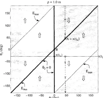
0 ~ <£' -50 p =1.0mand its rate of change
E
are shown in the plot. The minimum and the maximum contours of the errorE are denoted by Em in andEm a x respectively. In the shadedregions,
E
is negative, and it is positive in the unshaded regions. In each region, the evolution of 82 is governedby (10), and is indicated in the plots by large arrows,
Case 1. Exact convergence.
From Fig. 4, it can be seen that for almost all ¢, the 82 trajectory is drawn to the task position 82 = ¢. (One
such example is shown with point A (¢ = 45°).) This behavior is exhibited only for p= 1, i.e., when the task position lies in the post-failure workspace. We will see for any other value ofp,not only will exact convergence not be achieved (since the task position lies outside the post-failure workspace), but also the manipulator will almost always not converge to the point closest to that desired.
Even though exact convergence occurs for p = 1, the path taken by the end-effector is clearly not always the shortest. Also, the end-effector error initially in-creases for large regions of 82 and ¢, leading to large excursions of the second joint, which may violate joint limit constraints and therefore prevent convergence. It is also important to note that such behavior is not pre-ventable by simply restricting only the workspace (by limiting ¢) or only the robot configuration (by con-straining 82 ) ,
Case 2. Erroneous convergence.
We show two types of erroneous convergence. The first is the unique situation where the task position (B) is in the post-failure workspace, but the robot does not move at all (see Fig. 4). Here, x, and j1 are collinear Fig. 4. Joint-space trajectories for task positions A and B. Convergence to the task position is observed withA. No motion results when the task position is B.
I I I I ( ( ( » / -,, ,, , \ \ \ I B (2,0) (0.0),+-_ _= -1 -2 -2 -1 1.6 -2.5 L_ 3 ' : : : : : : --1.5 -0.5 0.6
g
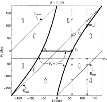
0 >.3In Fig. 5, the fh=
°
curve is discontinuous at positions81 and 82 . For the given value of p = 2.0, (h is non-zero at thesepositions (from (10)).
Four task positions that exhibit very different con-vergence behaviors are: A = (1,45°), B
=
(1,0°), C = (2,120°), D = (2,60°). In each case, the end-effector is initially positioned at x(to) = (1, -30°), with the robot configuration given by 81=
0°and 82=
-30°,and is commanded to move toward the task position un-til convergence. The joint-space trajectories for these cases are plotted in Figs. 4 and 5 as functions of 82 and
¢ (since 81 is always 0) for p = 1 and p = 2
respec-tively. For each particular task position, ¢ is constant and the trajectory evolves along the 82axis. For a given ¢, the task positions are characterized in these plots by 82 = ¢. Points of convergence are at the intersection of the trajectory of 82 with the task position, or with the
ih
= 0 curve3.Both the end-effector position errorE =
IIXd -
x.,II,
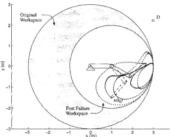
ax(m)
Fig. 3. A 2-DOF planar manipulator with the first joint failed at 0°. The shaded area represents the workspace of the healthy manipulator that reduces to the inner circle after the failure. Also shown in this plot are four task positions A, B, C, and D for which very different convergence behaviors are observed for the same starting position x(to).
Fig. 2. Geometric interpretation of the convergence condition from Theorem 1 for the 2-DOF Example. The manipulator con-verges when
x,
andj1 are collinear. Thus, motion of only the first joint (failed) is commanded, and therefore, the manipulator does not move.2
Post Failure
Workspace
Original Workspace
Fig. 6. Exact convergence to the task position A.
3 -1 -2 150 100 50 Oii<l) a :3-cD x(~)
Fig. 7. Erroneous convergence when the task position B is in the post-failure workspace. The manipulator converges to a configuration where the "reduced-manipulator" becomes singular
(03
=
7l"), and Xc andJi align.post-failure convergence remain even in this case, as we will demonstrate with a planar 3-DOF example. Still, kinematic redundancy holds great promise for improv-ing the convergence behavior through a judicious choice of inverse-kinematic control laws.
Allthe three distinct convergence behaviors are il-lustrated here, with four task positionsA = (1.5,120°), B = (1,90°), C = (3,131.8°), D = (3,48.2°). Pseu-doinverse control is assumed in these examples.
Fig. 6 illustrates the case when trajectory converges to the task position A. However, in Fig. 7it is shown that erroneous convergence may result, even though the task position B lies in the post-failure workspace. Fig. 8 illustrates the case when the task position lies out-side the post-failure workspace (but inout-side the original workspace), and the manipulator converges to a posi-tion other than the one that minimizes the end-effector
3 2 B o
~
.
:• ,X(t~)
. . .. ,"'.
••• \. : \. \. : .'/..,
. . . ;>' • / .:1 .. i /-.
(/ x(fu) -1 -2 -3 Original Workspace _3'--_-'-_ _ .L..-.._---'-':::=----''-''--1 2 -2go
c-,IV. A 3-DOF PLANAR EXAMPLE
Kinematic redundancy can be used to guaran-tee that the task positions lie within the post-failure workspace [3,4,5,6]. However, potential problems with and
iJ
2 = O. Indeed this condition is true for any 82 , and therefore the robot does not move for any initial configuration. Note that this behavior will be observed at every point on the boundary of the original workspace if the first joint fails with the appropriate value for 81 .The second, more common, type of erroneous con-vergence is observed when the task position is outside the post-failure workspace, Here, the end-effector does move, but converges to a point other than one that min-imizes the error, i.e., 82
=
1>.
One such example is the point C shown in Fig. 5.Fig. 5 indicates that even for a constant value of
p,very different errors may be observed at convergence depending upon the value of
1>.
The error is a minimum for 1> = 180°, and rises to a maximum for 1> close to 60°. For the special case when1>
= 60°, no convergence occurs; this is discussed next.Case 3. No convergence.
D is an example of a task position that lies outside the original workspace;and on the line Xd = 2. For such
points, (10) gives 82 = -Yd' Thus, the manipulator
rotates with a constant angular velocity.
Remarks: Joint-space plots such as those in Figs. 4
and 5 are valuable workspace layout tools. These plots can be used to identify "basins of convergence" where successful task completion can be achieved even in the presence of undetected joint failures.
Fig. 5. Joint-space trajectories for task positions C and D. The end-effector converges to a position that is not closest to C. With D, the manipulator does not converge at all, but cycles continuously.
3 D o 2 -1 -2 -3 Original Workspace _3'--_--L._ _- L_ _- - ' - ~ = _ __ _-=='---L-_ _-'--- _ __L__ _ 3 -2 -1
I
0 '>, -2 -1 _ 3 ' _ _ _ - - - L_ _- L_ _- - ' - ~ = _ _ _ = _ _ ' _ " " " ' ' _ _ _ _ _ ' _ __ __'_____ __'____ _ -3 3 2Fig. 8. Erroneous convergence when the task position C lies outside the post-failure workspace. Again, the manipulator con-verges to a configuration where the "reduced-manipulator" be-comes singular(113 = 0),andXcandjlalign.
Fig. 9. No convergence. With the choice of inverse-kinematics used, nonzero joint velocities are commanded in the healthy joints everywhere, therefore the manipulator does not converge.
error. Fig. 9 illustrates the case where no convergence is observed. In this case, the task point is specified to lie outside the original workspace. A potential conver-gence position, given by Theorem 1, coincides with a singularity of the unfailed manipulator. However, this presents no difficulty, since it is easily shown that the joint velocities commanded at the healthy joints, by the pseudoinverse, are continuous functions (this fol-lows from x, having no component along the singular direction). Moreover, at the singularity, the healthy joints are commanded non-zero velocities, establishing that convergence is not possible.
V. CONCLUSION
In this work the behavior of robotic manipulators performing point-to-point motion tasks with undetected locked-joint failures was analyzed. Conditions govern-ing convergence issues such as whether the manipu-lator comes to rest, and if so, at what terminal po-sition of the end-effector, were explicitly defined and the different possible convergence behaviors, illustrated with examples. The analysis also discussed the effect of faults on the manipulator workspace and presented valuableinformation for workspace layout. Our current work focuses on identifying appropriate kinematic con-trol schemes to address the problems identified here.
REFERENCES
[1] J. F. Engelberger, "Three million hours of robot field expe-rience," The Industrial Robot, pp. 164-168, June 1974. [2] M. L. Visinsky, J. R. Cavallaro, and 1. D. Walker, "Robotic
fault detection and fault tolerance: A survey," Reliability Eng. and Sys. Safety, vol. 46, pp. 139-158, 1994.
[3J A. A. Maciejewski, "Fault tolerant properties of kinemati-cally redundant manipulators," in Proc. 1990 Int. Conf. on Robot. and Auto., pp. 638-642, (Cincinnati, OR), May 13-18
1990.
[4] C. L. Lewis and A. A. Maciejewski, "Dexterity optimization of kinematically redundant manipulators in the presence of failures," Camp. and Elec. Eng., vol. 20, no. 3, pp. 273-288,
May1994.
[5] C. J. J. Paredis, W. K. F. Au, and P. K. Khosla, "Kine-matic design of fault tolerant manipulators," Camp. and Elec. Eng., vol. 20, no. 3, pp. 211-220, May 1994.
[6J R. G. Roberts and A. A. Maciejewski, "A local measure of fault tolerance for kinematically redundant manipulators,"
IEEE Trans. on Robot. and Auto., vol. 12, no. 4, pp.
543-553, August 1996.
[7J J. T. Chladek, "Fault tolerance for space based manipula-tor mechanisms and control systems," in Proc. ISMCR '90, First Int. Symp. on Meas. and Contr. in Robot., (Houston,
Texas), June 20-22 1990.
[8] E. Wu, M. Diftler, J. Hwang, and J. Chladek, "A fault toler-ant joint drive system for the space shuttle remote manipu-lator system," in Proc, 1991Int. Conf. on Robot. and Auto.,
pp. 2504-2509, (Sacramento, CAl, April 9-11 1991.
[9] M. L. Visinsky, J. R. Cavallaro, and 1. D. Walker, "Expert system framemwork for fault detection and fault tolerance in robotics," Camp. and Elec. Eng., vol. 20, no. 5, pp. 421-435,
September1994.
[10] M. L. Visinsky, J. R. Cavallaro, and 1.D. Walker, "A dy-namic fault tolerance framework for remote robots," IEEE Trans. on Rob. and Auto., vol. 11, no. 4, pp. 477-490,
Au-gust 1995.
[11] Y. Ting, S. Tosunoglu, and D. Tesar, "A control structure for fault-tolerant operation of robotic manipulators," in Proc. 1993 Int. Conf. on Rob. and Auto., pp. 684-690, (Atlanta,
Georgia), May2-6 1993.
[12J J. V. Draper, S. Handel, and C. C. Hood, "The impact of partial joint failure on teleoperation task performance," in M. Jamshidi and P. J. Eicker, editors, Robot. and Rem. Sys.: Proc. of the Fourth ANS Topic. Meet. on Robot. and Rem. Sys., pp. 433-439, (Albuquerque, New Mexico), February