Citation for the original published paper:
Albitar, H., Ananiev, A., Kalaykov, I. (2014)
Stability study of underwater crawling robot on non-horizontal surface.
In: Mobile Service Robotics: Clawar 2014: 17th International Conference on Climbing and
Walking Robots and the Support Technologies for Mobile Machines: Poznan, Poland 21 - 23
July 2014 (pp. 511-519). Singapore: World Scientific
N.B. When citing this work, cite the original published paper.
Permanent link to this version:
STABILITY STUDY OF UNDERWATER CRAWLING ROBOT ON NON-HORIZONTAL SURFACE
H.Albitar∗, A.Ananiev and I.Kalaykov
AASS, ¨Orebro University , ¨
Orebro, 70182, Sweden
∗E-mail: houssam.albitar@oru.se
www.aass.oru.se
This paper introduces a study of a concept of flexible crawling mechanism to design an industrial underwater cleaning robot, which is evaluated from the viewpoint of the capability to work underwater, scanning the desired surface, and bearing the reactions. This can be used as a robotic application in under-water surface cleaning and maintenance. In this study we focused on realizing the adhesion on the surface in stationary and in motion, bearing reactions, enabling the needed locomotion types for scanning, and achieving the stability in different situations on the surface.
Keywords: crawling robot; underwater; locomotion; stability
1. Introduction
Generally, surface cleaning takes place in 3D-spaces, but we consider the robot operating on a smooth nearly flat local 2D-space around it. Therefore the cleaning robot needs minimum two active (controllable) degrees of free-dom (2DOFs) to move. In addition, additional passive DOFs are needed to conform the robot’s structure to the concavity/convexity of the surface. We proposed1 an in-water crawling robot having four main subsystems,
namely: locomotion (crawling, rotation and stepping), adhesion (suction cups), cleaning (pressurized water jet), and neutralization of reaction forces (water jet reaction), details given in a previous publication.1
The locomotion subsystem is the basic component providing all move-ments of the robot. We selected the crawling mechanism because: it adapts to the surface, it can be used for different types of surface material, it is a simple mechanism, and it is stable with low center of gravity and large base support in the cleaning process.
when the suction cups are off in order to avoid critical situations.
In Section 2 we briefly describe the proposed robot prototype and its major functions and locomotion. The core of the paper is in Section 3, where two typical options are discussed, namely in stationary phase and in motion. The analysis is to find the minimum required force of vacuum suction cups and force of water jets to keep the robot in contact with the surface continuously. Conclusions highlight the main results.
2. The in-water cleaning robot and its locomotion
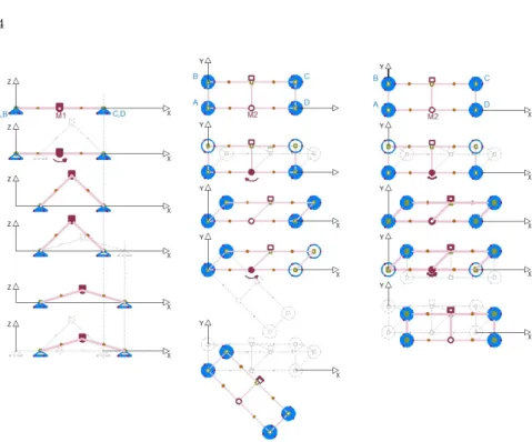
Fig. 1. The crawling robot
2.1. Robot concept
The seven links of the robot are connected through six joints (Fig.1), each joint has two rotational DOF RY and RZ, two motors are used M1 for
crawling and M2 for rotation and the rest joints are passive in both axes. The robot has a form of two parallel bipeds connected with three parallel links. To materialize the crawling motor M1 actively controls the angle between the legs to perform desired step size.
At the same time, both bipeds with the connecting links form two par-allelograms with three links parallel in all possible configurations. When motor M2 is moving, the rest joints passively follow the rotation.
Four suction cups are attached to the four corner joints ,each cup is surrounded by three small free wheels to minimize the friction of movement when any of these cups is not enabled (OFF-state).Due to the limitations of most of the adhesion techniques, we selected adhesion by suction cups for
their light weight and simple control that allows movement over arbitrary surfaces made of non-ferromagnetic materials.2This type of adhesion is well
developed and commercially available.
The cleaning subsystem contains two water jets directed on controllable varying angle to the surface. They are installed on one of biped links. The jets slide on these two links and a separate control system regulates the linear speed and time of cleaning in accordance to the nature of bio-fouling. A vision camera provides feedback to the human operator for the cleaning quality. We do not provide more details in this paper, as its focus is at the robot structure and operation.
In the cleaning subsystem, the force of the water being discharged from the jet nozzle creates an equal and opposite reaction, which makes the noz-zle recoil in the opposite direction of the water flow.3–5This effect becomes
stronger as water jet flow increases.
The cleaning water jets are directed at certain angle to the surface depending on the needs of the cleaning process. Therefore, the generated reaction force drags the robot away from the surface, for compensating and neutralizing the reaction force four dedicated waters jets are installed on the four links. While robot is in contact to the surface, thrust forces generated by these jets reinforce the adhesion. The water flow through the balancing jets is regulated such that the vector sum of all forces is nullified.
2.2. Robot locomotion
The robot moves at any X − Y surface direction by combining the two active DOFs RY and RZ, actuated by motors M1 and M2 respectively,
with ON/OFF activation of the suction cups. Enabled suction at one place and disabled suction at others gives the needed freedom of robot to move by activating M1 and M2 in coordinated way with suction cups’ acti-vation. By special control sequences the robot can perform three basic movements:crawling movement (on X-axis),changing orientation (rotation around Z-axis), and stepping forward (on Y -axis). Combining these move-ments the robot can scan the entire 2D space to be cleaned.
Crawling (on X-axis) is achieved by the pair of biped links , it is as-sumed the bipeds are at max-span pose (angle between the legs is 180◦) at initial position. The moving straight forward starts with switching OFF the rear pair of suction cups, and starting the crawling motor M1 to initiate contracting motion of both bipeds. After desired angle is achieved, M1 is stopped and the suction cups are switched ON again. The expanding motion is done by switching OFF the front cups, then M1 rotates in the opposite
Fig. 2. Possible robot locomotion types: crawling, rotation, stepping forward
direction. After a desired angle is achieved, M1 is stopped, and the suction cups are switched ON again, the robot is fixed at the final position (Fig.2). During the described movement, when any of the suction cups is OFF, there is a need to keep the robot in contact with the surface because the suc-tion cups have passive DOF around RY. Therefore, in the course of motion
neutralizing (balancing) water jets are activated. For maximum produc-tion rate, the cleaning is performed when the robot is immobilized into its max-span pose - all suction cups are ON and balancing jets are activated. This provides the center of robot’s mass close to the surface, which means maximum stability of the robot on the surface.
Changing orientation (rotation around Z-axis): While crawling is implemented by rotation around Y -axis, the changing of robot orientation is done by rotation around Z-axis. It can be performed around the center of any suction cup, meaning that there are four possible centers of rotation. Similar approach of applying a control sequence of activating/deactivating motor M2 and the suction cups is used. The sequence of rotating clockwise around suction cup A is illustrated in Fig.2. Similarly to crawling, during change of orientation the balancing jets are activated when any suction cup is OFF, as they all have passive DOFs around RZ.
Stepping forward (on Y -axis): Due to the non-holonomic properties of the robot construction, direct stepping forward on Y -axis cannot be performed. This is achieved by applying the same strategy of changing direction. In fact, we can do it as a consecutive execution of four rotations around Z-axis - around cup A and around cup C as shown on Fig.2. 3. Robot stability on the surface
In this study we discuss two typical cases when the crawling robot loses stability on a inclined surface - tumbling and sliding. Definitely, any of these two cases disrupts the normal motion and the robot control system should apply a compensating action. Obviously, the system must respond to the appearance of the the first event of sliding or tumbling. In this section, we are going to investigate the condition of these cases individually to assess the global robot stability.
Fig. 3. Robot simplified model
For the analysis, we consider a simplified model as shown on Fig. 3. Here, we assume that the weight of the robot is M g, friction between the suction cup and surface is µ, adhesion force of one suction cup is Fvacuum,
and balancing force of one jet is Fjet. We want to see what is the minimum
adhesion force to keep the robot on the surface only by means of suction cups without using the balancing jets,and the influence of the inclination angle α and the crawling angle θ (Fig. 3) on this force.
3.1. Robot stability in stationary phase
Tumbling appears also when the adhesion is not enough to keep the suction cups on the surface, but at lease one is still attached to the surface. Let us assume that an instant tumbling motion occurs around lower axle a-b. The moment generated by the adhesion force 2Fvacuum of suction cups C
5
our prototype. It was convenient to introduce this parameter for simplicity, then the required adhesion force Fvacuumof each suction cup is:
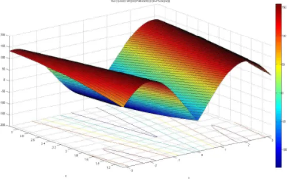
Fvacuum> M g 4 .(| sin α|.(p + cos θ 2) − cos α. sin θ 2) ,
Fig. 4 shows the adhesion force Fvacuumas a function of the crawling angle
60◦ 6 θ 6 180◦, and the inclination angle −180◦ 6 α 6 180◦ we have a
Fig. 4. Required adhesion to prevent tumbling - all cups are ON and M1 is OFF
minimum at α = 0◦and we notice that the crawling angle changes the posi-tion of the two maximums. The effect of α on the value of these maximums is not so important, so we can take the higher value as a required adhesion force for these maximums.
Sliding appears if the adhesion is not enough to keep all suction cups on the surface, such that external forces having orthogonal projection against the adhesion force can move the robot or slide it on the surface.
Following the same reasoning, stability against sliding of the robot can be provided if the friction generated by the negative pressure adhesion force by all four suction cups is larger than the force generated by its weight:
µ(4Fvacuum− M g| cos α|) > Mg sin α ,
yielding the required adhesion force Fvacuumof each cup to prevent sliding:
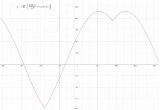
Fvacuum>
M g 4 (
sin α
Clearly, the required force Fvacuum to prevent sliding is independent of
crawling angle θ. Fig. 5 shows the adhesion force Fvacuumas function of α.
Fig. 5. Required adhesion prevent sliding - all suction cups are ON and M1 is OFF
From Fig. 5 and Fig. 4 we can get the needed force to maintain stable adhesion against sliding and tumbling. Clearly, the maximum of Fvacuum
for non sliding is greater than all the maxima in the non tumbling case. 3.2. Balancing force during crawling (motion phase)
When the robot start crawling, a pair of suction cups is OFF (according to Fig. 3 cups A and B are OFF) and the balancing water jet apply a force to maintain the adhesion on the surface during this movement. We analyze this case in similar way as in Section 3.1.
The moment generated by the balancing jets 2Fjetshould be larger than
the moment generated by the weight M g of the robot to maintain stable surface contact and not to tumble:
2Fjet.(1 − cos θ) > −M g.l. cos α. sin
θ
2 + M g.l.| sin α|.(p + cos θ 2) , yielding the required force for each balancing jet Fjet :
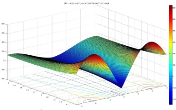
Fjet> M gl 2 . (| sin α|.(p + cosθ 2) − cos α. sin θ 2) 1 − cos θ
Fig. 6 shows the balancing force Fjet needed to keep the adhesion to the
surface during the crawling for crawling angle 60◦ 6 θ 6 180◦,and the inclination angle −180◦ 6 α 6 180◦. There is local minimum for α = 0◦ and the smaller the crawling angle the greater the two maxima are, that means in the control process when α is around +90◦ or −90◦, it is better
Fig. 6. Required water jet force for adhesion on the surface while the robot is crawling
3.3. Torque of M1 during crawling (motion phase)
The required torque for crawling is calculated by applying Newton’s second law P −→
Γ = J −→γ , assuming the angular velocity of M1 is constant then −
→γ =−→0 , we obtain: T −M g.l sin(θ
2−α)−2Fjet.l(1−cos θ)−µ.pl(4Fjetsin θ
2+M g.| cos α|) = 0 , and the torque of M1 during the crawling :
T = M g.l(sin(θ
2 − α) + µp| cos α|) + 2Fjet.l(1 − cos θ + µ.p sin θ 2) , Substituting Fjet we obtain the result shown on Fig. 7, which shows the
torque T needed during the crawling for 60◦6 θ 6 180◦, and −180◦6 α 6 180◦. It is clear that we need more torque when α 6 0◦ and the movement against the gravity, and in these cases the smaller θ the greater the required torque, so either motor M1 should bear these loads or the control process must avoid these cases and crawl with θ > 90◦ or more.
4. Conclusion
A new concept of crawling robot for in-water cleaning of surfaces is pre-sented in this paper. The design is based on minimalistic approach to achieve a compromise between maximum performance and reasonable com-plexity and cost of the system.
The solution is characterized by using minimum active DOFs (only two) for performing movements practically in all possible directions on a non-flat 2D surface. The available passive DOFs provide adaptability to local concavity/convexity of the surface to be cleaned.
Different types of unstable conditions related to the inclination of the surface and the crawling angle are considered and discussed for keeping contact with the surface in different situations. This stability study helps us in the future to estimate the adhesion force of the suction cups, also in the control of the needed balancing forces while the suction cups are in OFF-state as a function of the measured surface inclination angle and the robot pose to keep the robot stability.
References
1. H. Albitar, A. Ananiev and I. Kalaykov, New concept of in-water surface clean-ing robot, in Mechatronics and Automation (ICMA), 2013 IEEE International Conference on, 2013.
2. D. Sun, J. Zhu and S. K. Tso, Climbing & walking robots towards new appli-cations , p. 546 (2007).
3. X.-H. Li, Y.-Q. Zhu, G.-Q. Huang and S.-L. Nie, Journal of Chongqing Uni-versity (English Edition). China 8, 63 (2009).
4. G.-q. Huang, Y.-s. Yang, X.-h. Li and Y.-q. Zhu, Journal of Shanghai Univer-sity (English Edition) 13, 305 (2009).
5. S. Guo, X. Lin and S. Hata, A conceptual design of vectored water-jet propul-sion system, in Mechatronics and Automation, 2009. ICMA 2009. Interna-tional Conference on, 2009.