Doctoral Thesis in Aerospace Engineering
Enhanced Composite Joint
Performance through Interlacement
of Metal Inserts
SAHAR AKBARPOUR
Stockholm, Sweden 2021 www.kth.se ISBN 978-91-7873-920-2 TRITA-SCI-FOU 2021:22KTH ROYAL INSTITUTE
OF TECHNOLOGY
SAH AR AK BAR PO UR En ha nc ed C om po sit e J oin t P erf orm an ce t hro ug h I nte rla ce m en t o f M eta l I ns ert s K TH 2 02 1Enhanced Composite Joint
Performance through Interlacement
of Metal Inserts
SAHAR AKBARPOUR
Doctoral Thesis in Aerospace Engineering with Specialisation in Lightweight Structures
KTH Royal Institute of Technology Stockholm, Sweden 2021
Academic Dissertation which, with due permission of the KTH Royal Institute of Technology, is submitted for public defence for the Degree of Doctor of Philosophy on Friday the 11th of June 2021, at 10:15 a.m. in E32 Lindstedtsvägen 3, Stockholm.
© Sahar Akbarpour ISBN 978-91-7873-920-2 TRITA-SCI-FOU 2021:22
Preface
The work presented in this doctoral thesis has been carried out in the Division of Lightweight Structures, Department of Engineering Mechanics, Royal Institute of Technology) KTH and was funded by the EC FP7 project 314003, Low Cost Manufacturing and Assembly of Composite and Hybrid Structures (Locomachs) and the Swedish Aeronautical Research Programme NFFP7, Vinnova project 2017-04877. The financial support is acknowledged. SAAB AB is gratefully acknowledged for manufacturing test specimens.
Firstly, I would like to express my deepest gratitude to my supervisor, Dr Stefan Hallstr¨om for introducing me to the field, and for his guidance and encouragement. I really appreciate the many constructive discussions we have had.
My colleagues and friends at KTH Lightweight Structures, as well as SAAB AB are thanked for creating a cheerful work environment and for all the nice talks and discussion. I especially thank Tommy Grank¨all for his assistance with the administration around the manufacturing of the test specimens. I would also like to acknowledge Linus Fagerberg at Lightness by Design for his practical suggestions regarding some of the numerical simulations.
Words are not enough to express my gratitude to my parents, Farkhonde and Ali for their never-ending love and support. I also wish to thank my sister and brother, Sara and Saeid who never wavered in their love and encouragement.
Finally, I would like to extend my sincere thanks to my beloved husband, Kurosh who has been there for me in the tough times. Thank you for being my best friend during these years. I am grateful to have you and Adrian in my life.
Stockholm, May 2021.
Abstract
The work in this thesis investigates bolted joints in fibre reinforced composites with particular focus on a novel insert concept. The concept is characterised by replacing all composite plies with stacked metal patches, locally around a bolt hole, so that they jointly form a solid metal reinforcement. An extensive experimental study is presented together with finite element analysis of the studied cases.
Reinforcing bolt holes with high-strength metals improves the bearing load capacity of the composite laminates. True enhancement of the joint performance however re-quires that the open-hole tensile strength is improved as well. The work started with tests of pin-loaded and open-hole tensile specimens with inserts, and significant im-provement of the bearing load capacity was found. The initial tests enabled more in-formed design, and insert configurations having sufficient open-hole tensile strength could thereby be manufactured and tested. In parallel, composite-metal joints were numerically modelled to simulate and analyse the mechanical performance of the joints and gain a better understanding of the governing damage mechanisms. The performance of the joints was eventually investigated by means of experiments on single-shear, single- and double-bolt specimens, with and without inserts. The allowable bolt distance and the influence from the bolt tightening torque were also examined.
The initial samples had inserts of stainless steel. Later, specimens with titanium alloy inserts were also included in the test series. Various insert configurations were designed to study the effects of different features in the composite-metal bond lines. The numerical simulations of the composite–metal interfaces were performed with two types of models, one joining the two materials directly to each other, without modelling any adhesive film in between, and the other including an elastic representation of the adhesive layer. The experimental results were then used to support verification of the results from the simulations.
The final assessment of the concept was performed on insert configurations designed either for pure tensile loading or for more general (bi-directional) loading conditions, and the bearing load capacity, open-hole tensile strength and the performance of bolted joints were compared for cases with different inserts. While higher bearing strength improvement was achieved when the holes were reinforced with inserts of stainless steel, reinforcement with inserts of titanium was even more successful since it improved virtually all studied aspects of the joints considerably.
Sammanfattning
Arbetet som presenteras i avhandlingen unders¨oker bultf¨orband i fiberarmerade kompositmaterial med s¨arskilt fokus p˚a ett nytt insert-koncept. Konceptet definieras av att kompositmaterialet n¨armast h˚alet ers¨atts med metall genom att partiellt byta ut lagren i kompositen med tunna metallskikt som tillsammans bygger upp en solid metallf¨orst¨arkning. En omfattande experimentell studie ¨ar genomf¨ord tillsammans med finita elementanalys av de studerade fallen.
F¨orst¨arkning med h¨ogh˚allfasta metaller f¨orb¨attrar b¨arigheten hos h˚alen i komposit-materialet. En komplett f¨orst¨arkningseffekt kr¨aver dock ¨aven att dragh˚allfastheten hos den perforerade kompositen f¨orb¨attras. Forskningsarbetet b¨orjade med att un-ders¨oka pinn-belastade h˚al och dragh˚allfastheten hos provstavar med h˚al och inte-grerade inserts, och en tydlig f¨orb¨attring kunde p˚avisas. Tidiga tester m¨ojliggjorde en b¨attre utformning av efterf¨oljande konfigurationer s˚a att de erh¨oll en tillfreds-st¨allande h˚allfasthet ¨aven i ren dragbelastning. Parallellt med det experimentella arbetet utvecklades numeriska modeller av de studerade konfigurationerna f¨or att b¨attre kunna analysera deras mekanik och h˚allfasthet.
Kapaciteten hos f¨orbanden unders¨oktes sedan genom provning av enkelsk¨arande ¨
overlappsfogar med enkelt eller dubbla f¨astelement, med och utan inserts. Tillb¨orliga kantavst˚and och effekten av olika ˚atdragningsmoment unders¨oktes ocks˚a.
Den ursprungliga provningen utf¨ordes med inserts gjorda av rostfritt st˚al. Senare testades ¨aven inserts gjorda av en titanlegering. Olika insert-konfigurationer togs fram f¨or att studera effekterna av olika detaljer i fogarna mellan metallerna och kompositmaterialet. Datorsimuleringarna genomf¨ordes med tv˚a olika typer av mo-deller; en d¨ar de olika materialen var stumt fogade till varandra, utan att modellera limfilmen emellan, och en annan som anv¨ande en elastisk beskrivning av limmet. De experimentella resultaten anv¨andes sedan f¨or att verifiera resultaten fr˚an de nume-riska simuleringarna.
Den slutgiltiga utv¨arderingen av konceptet genomf¨ordes p˚a konfigurationer som ta-gits fram antingen f¨or renodlad dragbelastning eller f¨or mer generell (bi-axiell) be-lastning. H˚alkants- och dragh˚allfastheten unders¨oktes tillsammans med b¨arf¨arm˚agan hos bultf¨orband och j¨amf¨orelser gjordes mellan fall med olika inserts. Konfigura-tionerna med inserts av st˚al uppvisade den h¨ogsta h˚alkantsh˚allfastheten medan de med titan-inserts presterade b¨attre totalt sett. De senare uppvisade p˚atagliga f¨orb¨attringar av samtliga unders¨okta egenskaper.
Dissertation
This doctoral thesis contains an introduction to the research area and the following appended papers:
Paper A
Reinforcement around holes in composite materials by use of patched metal inserts Sahar Akbarpour and Stefan Hallstr¨om
Composite Structures, 225:111084,2019
Paper B
Strength improvement of bolted joints in composite materials by use of patched metal inserts
Sahar Akbarpour and Stefan Hallstr¨om Composite Structures, 252:112628,2020
Paper C
Experimental investigation and numerical analysis of multi-material interfaces re-lated to a composite joint concept
Sahar Akbarpour and Stefan Hallstr¨om
Report TRITA-SCI-RAP 2021:005, KTH Engineering Sciences, Royal Institute of Technology, Stockholm, Sweden
Paper D
Enhancing the performance of bolted joints in composites by use of patched steel or titanium inserts
Sahar Akbarpour and Stefan Hallstr¨om
Report TRITA-SCI-RAP 2021:006, KTH Engineering Sciences, Royal Institute of Technology, Stockholm, Sweden
Submitted for publication
The author’s contribution to the appended papers
Paper A
Akbarpour and Hallstr¨om planned the experimental study. Akbarpour designed
the test specimens, assisted during manufacturing and performed the experiments. Akbarpour conducted the numerical analysis and wrote the first draft of the paper. The final manuscript was then jointly finalised by the authors.
Paper B
Akbarpour and Hallstr¨om planned the experimental study. Akbarpour designed the test specimens and helped with the manufacturing and performed the experiments. Akbarpour wrote the first draft of the paper. The final manuscript was then jointly finalised by the authors.
Paper C
Akbarpour planned the experimental study, designed the test specimens, assisted during manufacturing and performed the experiments. Akbarpour also conducted the numerical analysis and wrote the first draft of the paper. The present manuscript was then jointly written together with Hallstr¨om.
Paper D
Akbarpour planned the experimental study, designed the test specimens, assisted during manufacturing and performed the experiments. Akbarpour wrote the first draft of the manuscript which was then jointly finalised by the authors.
Contents
Introduction 1
Background . . . 1
The reinforcing insert concept . . . 3
The composite-metal joints . . . 4
Numerical simulations . . . 8
Manufacturing and mechanical testing . . . 9
Insert design . . . 11
Summary of appended papers . . . 16
Future work . . . 18 References . . . 19 Paper A A1-A10 Paper B B1-B12 Paper C C1-C38 Paper D D1-D25 xi
Introduction
Background
Composite materials, and carbon fibre reinforced polymers (CFRP) in particular, are widely used in aircraft structures due to their superior mechanical properties and low density. In addition, composite materials have good fatigue properties and are corrosion resistant. Hence, they are being increasingly used in load carrying structures in a broad range of applications. An illustration of the use of different materials in the Airbus A350 XWB aeroplane is shown in Fig. 1.
Figure 1: Ratios of the material used in Airbus A350 XWB [1]
The manufacturing technologies of composite materials allow for integration of com-ponents and production of large and complex parts. Fig. 2 shows an A350 XWB lower wing cover from inside Airbus’ manufacturing site, illustrating the size and
Figure 2: An A350 XWB lower wing cover at Airbus’ composite manufacturing site [2]
complexity of a state-of-the-art composite structure. Another example of a com-plex CFRP component, developed within the EU CleanSky programme is shown in Fig. 3. Still, composite components are often joined together using fasteners since that permits relatively easy disassembly and inspection. Mechanical fastening is a well-established technique for joining both metallic and composite parts but in composites, the structural efficiency, i.e. the ratio of the joint strength to the ultimate strength of the adherent laminates, is relatively low. This is attributed to low bearing load capacity as well as brittleness and notch sensitivity of the CFRP materials. In fact, the strength of bolted joints in composites can barely exceed half the strength of the un-notched laminates [3].
Reinforcing bolt holes with high strength metals is an effective way to increase the bearing load capacity of composite materials. Various reinforcing concepts can be
Figure 3: An example of a complex CFRP wing shell. Courtesy of SAAB
found in the literature. Nadler et al. [4] suggested using thin metal sheets in between the composite plies, hence avoiding ply interruption. The concept generated a thicker laminate at the joint contributing to some secondary effects like local bending. An alternative option that avoids local thickening is to replace some of the composite plies with metallic layers.
A ”lamella coupling” concept was investigated by Fink et al. [5] and Camanho and Lambert [6] where some of the composite plies were replaced with titanium sheets. The lamella coupling concept, was used around bolt holes and could improve the specific tensile strength of a double-lap bolted joint by about 30% [7-11]. More recently, a study investigating the effect of local hybridization with steel foils in thin- and thick-ply CFRP laminates was presented by K¨otter et al. [12], where the open-hole tension and bearing strength were investigated.
The reinforcing insert concept
In this study, an insert concept that locally replaces composite plies with metal patches of various diameters is investigated. A photo of a test specimen with such an insert and a corresponding schematic sketch is shown in Figs. 4a and 4b. The main problem with mechanical fasteners in composite materials is the relatively poor bearing strength compared to metals. The proposed insert concept replaces the composite material with metal, locally around the hole. The second challenge is the anchorage of the inserts in the composite material and that is done by interlacing the inserts ply-wise between the composite lamellas. The load between the fastener and the hole edge then transfered purely from metal to metal, avoiding compression failure due to delamination which is known to be a problem for composite materials. On the outer perimeter of the inserts, the metal is joined with the surrounding composite material through ”finger joints”, i.e. layered overlapped interfaces that increase the effective joint area for more efficient load transfer between the metal and the composite material. In most studies of fastener joints in composite materials considerable emphasis is put on e.g. fastener clearance, tilting and bending, quality of the hole edges, et cetera. Such aspects are however not that essential for the present concept and are thus to a great extent omitted in this study. Instead, the main challenge and focus of this work is to design and optimise insert configurations so that composite-metal debonding is avoided and final failure is governed by the bearing strength of the metal inserts.
(a) (b)
Figure 4: A pin-loaded test specimen with a metal insert (a) and corresponding schematic sketch showing stacked metal patches (b)
The composite-metal joints
The inserts are built by alternately placing metal patches of various diameters through the thickness of the composite laminate. By alternating the patch diameter, circumferential finger-joints are formed between the metal patches and the surround-ing composite plies (see Fig. 4b). The strength of the composite-metal fsurround-inger-joints is crucial for successful and reliable implementation of the concept.
The composite-metal interface consists of overlapping and butted parts. The inserts are designed such that the area of the overlapping part is much larger than the butted part. Thus, the main part of the load transfers through the overlapping interface and the ultimate strength of the composite-metal interface primarily relies on its overlapping parts.
Since the butted parts of the interface constitute a much smaller share of the total interface area the joints might sustain partial failure there, but such damage is then also likely to grow into the adjacent overlapping parts of the interface, with disastrous consequences.
In order to approach the challenges related to the anchorage of the metal into the composite material some general aspects of multi-material interfaces first need to be understood. In short, joining dissimilar materials is a mechanically complicated matter.
Firstly, differences in stiffness between the materials cause poor compatibility since the two materials then tend to deform differently when loaded, but are prevented to do so at an interface they share. Similarly, if the two materials have different coef-ficients of thermal expansion (CTE) stresses will arise in the joint by just changing the temperature, i.e. even without trying to transfer load between the adherends. In addition to this, sharp geometrical features in the joined interfaces such as edges and corners will be sites of severe stress concentrations, and when modelled with theory of elasticity such sites even become singular.
Line of symmetry Interface-1 A B A B -2 0 2 4 6
Along overlapping interface from point A to B
Strain
(%)
Shear strain Normal strain
Figure 5: Shear and normal strains along an overlapping interface of a composite-metal finger-joint
A qualitative distribution of shear and normal (transverse) strains along an overlap-ping interface (interface-1) of a composite-metal joint is shown in Fig. 5. Extreme strain levels occur at the corner points A and B while the strains in the rest of the bond line can be well described by basic mechanical principles, governing the strain distribution along (idealised) bonded joints.
Schematic Fig. 6 illustrates strain distribution along an idealised adhesively bonded joint between adherends with different stiffnesses or different CTEs. The Young’s moduli and the CTEs of the two adherends (1 and 2) are E1 and α1, and E2 and
α2, respectively (Fig. 6a). It is assumed that the Young’s modulus of the adhesive
is significantly lower than E1and E2and its shear modulus is denoted G. Figs. 6b,
6c, and 6d show shear strains along the bond line when the load F is applied. If the adherends are rigid (Fig. 6b) the shear strain in the adhesive is constant along the bond line. If on the other hand, the adherends deform elastically due to the applied load, but have identical stiffness, the strain distribution depicted in Fig. 6c is obtained, where the highest strains are found at the boundaries of the bond line. In Fig. 6d the strain distribution for the case of two adherends with different elastic moduli is shown. For this case the shear strain increases towards the borders of the interface and is higher at one end than the other (γB> γA> γ2if E1< E2).
The strains from an applied thermal load generated by a temperature difference ∆T is shown in Fig. 6e. No thermal expansion of the adhesive itself is included in the figure. For this case the highest strains are again found at the boundaries of the bond line, but with opposite signs, and the strain is zero in the middle. It
Adherend E2, α2 Adhesive G Adherend E1, α1 (a) No load γ0 γ0 γ0 F F E2=∞ E1=∞ (b) Mechanical load, E1= E2=∞ γ γ γ1 F F E2= E E1= E
(c) Mechanical load, E1= E2andγ > γ1
γB γA γ2 F F E2 E1< E2
(d) Mechanical load, E1< E2andγB> γA> γ2
γ3= 0
γα γα
α2
α1< α2
(e) Thermal load (∆T > 0)
Figure 6: Schematic sketches showing shear strain in an adhesively bonded joint under mechanical or thermal loading
should be noted that in the case of an adhesively bonded joint between a metal and a composite material, the shear modulus of the composite layer is matrix dominated
and therefore not very much higher than for the adhesive.
In addition, the effect from the stress concentrations at the multi-material corners should be included in the analysis. That is, the geometry of the interface and the mismatch of material properties of the adherent layers are also paramount for the stress situation at the composite-metal bonds. The failure mechanisms of the composite-metal finger-joints are quite complicated and could both lead to adhesive failure, adhesion failure and to crack initiation and fracture in the adherends. Hutchinson [13] investigated the stresses and the failure modes typically seen in thin films and layered materials. Some modes of cracking for a film on a substrate are shown in Fig. 7. A crack in the film may penetrate into the substrate (Fig. 7a) if the substrate is brittle. The interface may debond in the form of a bi-material crack (Fig. 7b), or what starts as a bi-material crack in the interface may kink and propagate further into the substrate (Fig. 7c). Fracture in the films and substrates can in many cases be successfully analyzed using a linear elastic fracture mechanics (LEFM) approach.
(a) Substrate damage (b) Debonding (c) Interface–substrate crack
Figure 7: Common failure modes of thin films [13]
The stresses close to multi-material corners are in general singular and similar to the stresses in the vicinity of a crack tip. Fig. 8 shows multi-material corners occurring at a joint, where the singular stresses can be analyzed using the theory of LEFM. Using a polar co-ordinate system (r, θ), the stress state in the singularity dominated zone of a corner point located at r = 0 can be written as
σij=
X
m
Re[Qmrλm−1fijm(θ)] i, j = 1, 2 (1)
where the generalized stress intensity factors, Qm, are determined from peripheral
conditions such as external loads and geometry. λm express the strength of the
r-dependence for the different terms and are governed from the corner geometry and the constitutive properties of the involved materials.
The singularity analysis of various multi-material corner configurations composed of isotropic or anisotropic materials have been studied intensively in previous literature, e.g. [14-18]. In this work, an attempt is made to make use of similarities between
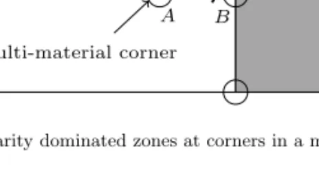
r X Y θ A B Metal Composite Multi-material corner
Figure 8: Singularity dominated zones at corners in a multi-material joint
local corner configurations, comparing the magnitude of their stress intensity factors in order to rank the strength of different composite-metal joints.
Numerical simulations
Finite element (FE) models were used to analyze stresses at the composite-metal interfaces surrounding the inserts. Residual stresses from cooling to room tempera-ture after curing at 180◦C were included by applying a thermal load corresponding
to ∆T =−160◦C.
First, two-dimensional (2D) FE models are used to analyze idealized composite-metal joints with block-ply laminates consisting of only 0◦- and 90◦-plies. No
adhe-sive layer is modeled at the interfaces, assuming that the adheadhe-sive layer is infinitely thin. The FE stress analysis of the idealized joints is presented in Paper A [19] together with the results from experiments.
In Paper C, narrow 3D models representing a lengthwise slice of the joints through the thickness are used. The interfaces were first modeled omitting the thin adhesive layers, making the interface infinitely stiff. In a second round of simulations the adhesive layers were included in the models by means of elastic contact between the joined materials. The FE models were used to analyze the stress concentrations as well as the strength of the joints. Afterwards, the stress intensity factors were extracted from the models with infinitely stiff interface and identical multi-material corners in various joints were compared. No clear relation between the stress inten-sity factors and the failure load of the composite-metal bonds could be found and the author did thus not succeed to outline a failure criterion based on stress intensity factors.
It was then assumed that the idealised models with infinitely thin bond lines made the joints unrealistically stiff, overestimating the stress concentrations at the corners. A new approach was made, combining and comparing the results from the above
models with results from models with softer elastic bond lines.
Manufacturing and mechanical testing
The inserts were built together with the composite laminate, by hand layup of prepreg composite plies and placement of metal patches in holes cut a priori in the pregreg plies. The patches forming the inserts were laser cut from sheet metal and a thin adhesive film was pressed onto one side of the patches for metal-metal bonding and to enhance the composite-metal adhesion. The manufacturing procedure is presented in detail in Paper A.
The manufacturing procedure used in this study is obviously quite labour-intensive. The concept is however designed and intended for more automated manufacturing, e.g. with tape-laying of the composite plies and application of the metal patches with pick-and-place technology, or similar.
First, pin-loaded and open-hole tensile specimens with inserts were manufactured and tested together with reference specimens without inserts. The pin-loaded tests were performed to investigate the bearing strength of the specimens with inserts while the open-hole tests were conducted to explore whether the inserts affect the tensile strength of the composite laminates. In addition, some simplified specimens with strip inserts (see Fig. 9) were manufactured for more generic comparison of the strength of different composite-metal interfaces.
Figure 9: Tensile test specimen with strip insert
The reinforcement concept was finally investigated by means of single-shear lap joints. Schematic sketches showing single- and double-bolt joints are shown in Figs. 10 and 11. The results from the single-shear tests are presented in Paper B [20] and D.
Insert F
F
Figure 10: Single-shear single-bolt joint with insert
Insert Insert F
F
Figure 11: Single-shear double-bolt joint with inserts
Specimens with single-bolt joints show bearing failure if they are wide enough, whereas narrower specimens fail due to insufficient net-section area. Figs. 12a and 12b show examples of bearing and net-section failure of reference specimens without inserts.
The influence from the relative hole size, i.e. diameter/hole distance, on the struc-tural efficiency of a double-shear single-bolt joint in high strength carbon-epoxy lam-inates was presented by Hart-Smith [3] and later developed by Fink and Camanho [21]. A principal reproduction is presented in Fig. 13. The thick curve indicates an optimised situation with net-section failure for smaller bolts (or wider spacing) and bearing failure for larger bolts (or narrower spacing). If the bearing strength increases, a larger bolt spacing is required to avoid net-section failure and there-fore the structural efficiency does not increase proportionally. The specific strength (strength per weight) is however improved since a similar load can be transferred through a joint with larger bolt spacing, i.e. fewer bolts per unit width.
The efficiency truly increases if both the bearing strength and the open-hole tensile strength are improved. Fig. 12c shows bearing failure of the insert due to plastic deformation at the hole edge, which happens if the specimens have sufficiently high tensile strength. If the tensile strength is not sufficient, the specimens fail due to debonding of the insert, leading to subsequent net-section failure as illustrated in Fig. 12d. F (a) F (b) F (c) F (d)
Figure 12: Bearing and net-section failure of reference specimens (a and b), and bearing and tensile failure of specimens with inserts (c and d)
For the initial tests, the inserts were made of stainless steel but later inserts were also made of a beta titanium alloy, in the following simply referred to as ”titanium”.
0 0.2 0.4 0.6 0.8 1.0 10 20 30 40 50 Basis laminate Bearing failure
Increasing bearing strength Increasing strength Net-section failure Diameter-to-width ratio Join t structural efficiency (%)
Figure 13: Effect of net-section and bearing strength variations on joint efficiency [21]
Papers A and B present results from specimens with steel inserts only, while Papers C and D include results from specimens with both steel and titanium inserts. Pin-loaded, open-hole tensile and bolted joint tests were performed according to ASTM D5961 [22] with minor deviations in the specimen dimensions, believed to be insignificant. The 2% offset strength method suggested in the standard was used to describe the bearing strength. The strains on one surface of the specimens were plotted through use of digital image correlation (DIC) of images recorded during the test, using a GOM Aramis 5 M Rev.02 DIC system.
Insert design
The concept is built on the principle of replacing composite plies with metal patches of various diameters as seen in Fig. 4b. In this study, patches with two different diameters, i.e. 14 and 24 mm, are used throughout the work. Every two composite plies are replaced with one 0.2 mm thick metal patch through the thickness of the laminate. All prepreg plies have either 14 or 24 mm holes for inserting small or large patches. The carbon fibres are cut even in the 0◦-plies and the load paths in
the lamina are interrupted by the holes. While designing the insert configurations, cutting large holes in the 0◦-plies are avoided. Large holes are first cut in 90◦-plies and then in 45◦-plies, if needed.
Some insert configurations designed for the highest strength in the longitudinal (fibre) direction are shown in Fig. 14. The nomenclature below each insert config-uration, e.g. St6–I4, describes the stacking sequence of the composite laminate in
90 90 90 -45 -45 -45 0 0 0 45 45 45 LOS (a) St6-I4 0 0 0 45 45 45 90 90 90 -45 -45 -45 LOS (b) St8-I5 90 90 90 -45 -45 -45 0 0 0 45 45 45 LOS (c) St9-I6 -45 -45 -45 0 0 0 90 90 90 45 45 45 LOS (d) St16-I12 Figure 14: Insert configurations designed for longitudinal loading
(St6) as well as the insert geometry (I4). A last part indicate whether the insert is made of steel (St) or titanium (Ti). Avoiding large holes in 0◦-plies is the first
design guideline. The next step is to properly match the composite plies to the metal patches. For example, if a 0◦-ply meets a large patch with an overlapping
interface then the load transfer between the composite and the insert will be more efficient. The guidelines for designing insert configurations are outlined in Paper A. That paper presents results from testing specimens with strip inserts (see Fig. 9) and suggests a simple engineering model to estimate the strengths of specimens with circular inserts using the strengths of identical composite-metal interfaces extracted from specimens with strip inserts (see Fig. 15). A sketch of specimens with circular inserts and the corresponding engineering model are shown in Figs. 15a and 15b respectively.
The insert configurations shown in Fig. 14 are used in pin-loaded and open-hole ten-sile tests. While the ultimate failure loads from the pin-loaded tests vary only slightly between the configurations, the open-hole tensile strength varies considerably more. The configuration with the highest open-hole tensile strength was chosen for the tests of bolted joints with steel inserts. The results from the pin-loaded, open-hole tensile and bolted joint specimens with steel inserts are presented in Paper B. The insert configurations should be designed according to the guidelines when the metal patches are made of steel. Otherwise, the specimens may show undesired net-section failure due to insufficient tensile strength. The specimens with titanium
inserts however, show a higher open-hole tensile strength than references even if the design guidelines are violated. Two of the insert configurations that are designed for bi-directional loading by violating the design guidelines are shown in Fig. 16. In these configurations the overlapping interfaces between the 90◦-plies and the
large patches enhance the load transfer in the transverse direction. The open-hole tensile strength of specimens with steel and titanium inserts are compared with references without inserts in Fig. 17. The specimens with titanium inserts show up to 30% improvement in open-hole tensile strength compared to the references. This very promising result indicates that the structural efficiency of bolted joints can be improved considerably (see Fig. 13) since the concept not only increases the bearing strength but also the open-hole tensile strength of the composite laminates. The results from the pin-loaded, open-hole tensile, and bolted joint specimens with titanium inserts are presented in Paper D together with the results from similar specimens with steel inserts. As an example, a bearing stress-strain curve from single-shear testing of a bolted specimen with titanium inserts at both holes is shown in Fig. 18 together with a curve from a reference specimen. The curves clearly show a considerable improvement for the specimen with inserts. The final failure was governed by bolt failure for both the reference and the specimen with inserts. Some of the cases with bolted specimens reinforced with steel inserts show tensile failure. A photograph of a specimen showing such failure is shown in Fig. 19. Al-though the tensile failure happened at a load considerably higher than the ultimate load of the references, it is not a desired failure mode for bolted joints. The strain field obtained from image processing of photos taken during testing of a bolted speci-men is shown in Fig. 20. The figure shows the longitudinal strain field on the surface of a specimen with steel inserts at both holes, just before failure. Highly strained regions coinciding with the edge of a large patch located underneath the surface can be seen through the composite plies on top of it. The strain field indicates that the composite-metal debonding initiated underneath the surface of the specimen. The
d1 d2 d2 w (a) d1 d1 d2 w (b)
Figure 15: Schematic sketch of specimens with circular insert (a) and the corresponding model (b).
90 90 90 -45 -45 -45 0 0 0 45 45 45 LOS LOS (a) St6–I5 -45 -45 -45 0 0 0 90 90 90 45 45 45 LOS LOS (b) St18–I12 Figure 16: Insert configurations designed for bi-directional loading
0 10 20 30 40 50 60 44 .1 38 .4 56 .8 43 .9 55 .4 35 .5 48 .7 29 .7 47 .9
Tensile specimens with stainless steel or titanium alloy inserts
F ailure load (kN) Reference St6–I4–St St6–I4–Ti St16–I12–St St16–I12–Ti St6–I5–St St6–I5–Ti St18–I12–St St18–I12–Ti
Figure 17: Ultimate failure loads of open-hole tensile specimens with steel or titanium inserts
0 0.05 0.1 0.15 0.2 0.25 200 400 600 800 1000 Bearing strain Bearing stress [MP a] Reference
Specimen with inserts
Figure 18: Bearing stress-strain curves from single-shear testing of double-bolt specimens
strain field images from the specimens failing due to composite-metal debonding indicate initiation of failure underneath the surface in most of the cases.
No tensile failure was observed for the pin-loaded or bolted joint specimens with titanium inserts investigated in this study. Even the specimens with inserts designed for bi-directional loading had in all cases sufficiently high tensile strength and as a result all such specimens showed bearing failure. A photo showing a failed single-shear double-bolt specimen with titanium inserts is shown in Fig. 21.
Figure 19: Tensile failure of a single-shear double-bolt specimen with steel inserts at both holes
Figure 20: Longitudinal strain field on the surface of a single-shear double-bolt specimen with steel inserts at both holes, just before failure
Figure 21: Bearing failure of a single-shear double-bolt specimen with titanium inserts at both holes
Summary of appended papers
Paper A: Reinforcement around holes in composite materials by use of patched metal inserts
The initial investigation of the reinforcement concept was done by tensile testing of specimens with strip or circular steel inserts. The specimens had simplified insert configurations and block-ply laminates and were tested to identify key parameters for proper composite-to-metal joining. Some design guidelines were outlined based on the results from the initial tests and a “good” insert configuration was examined by means of pin-loaded and open-hole tensile tests. A configuration deliberately designed for poor performance was also tested for comparison. The pin-loaded spec-imens with inserts showed up to 60% improvement in strength. The open-hole tensile strength however, was lower than for the references. Results from pin-loaded testing of specimens with a “hybrid” configuration were also presented. In addition to the experimental study, two-dimensional FE analysis was performed to investigate the stresses at the composite-metal interfaces.
Paper B: Strength improvement of bolted joints in composite mate-rials by use of patched metal inserts
An extensive experimental study that included pin-loaded, open-hole tensile, and single-shear testing of specimens with steel inserts was presented. Four optimised insert configurations were designed for pin-loaded and open-hole tensile testing. It was shown that the bearing load capacity of composites improves 50–60% if the holes are reinforced with steel inserts. The improvement in open-hole tensile strength was up to 20%. The insert configuration with the highest open-hole tensile strength was then used for manufacturing of some bolted specimens. Single- or double-bolt specimens with inserts showed more than 25% improvement in strength. Only one of the bolt-holes was reinforced with inserts in the double-bolt specimens tested in these test series. Allowable bolt distances were also studied through pin-loaded testing of specimens with reduced widths. There was no indication from the results that the bolt distance allowables need to be changed for specimens with inserts, even though the failure loads were more than 50% higher than the references without inserts. Moreover, the effect of an increased bolt fastening torque on the strength of the joints with or without inserts was investigated.
Paper C: Experimental investigation and numerical analysis of multi-material interfaces related to a composite joint concept
Composite-metal interfaces were investigated experimentally and numerically. The strength of various interface geometries between composite and steel or titanium was studied by means of tensile testing of specimens with strip inserts. The strength of interfaces with or without adhesive films was compared and it was shown that an added adhesive film enhanced the strength of the joints. In addition, identical inter-faces were tested at reduced and elevated temperature and the results from the tests were compared. The results show that the strength of the bonds decrease consider-ably with increasing temperature. Two modeling approaches, one with an infinitely stiff interface and one including an elastic adhesive film, were presented. The mod-els were used to analyse stress concentrations at the multi-material corners and also the strength of the different configurations. None of the two models could provide a complete representation of the stress fields but they showed that some multi-material corners experienced higher stress concentrations than other. The strain field images recorded during testing showed highly strained regions corresponding to the corners with high stress concentrations in the models.
Paper D: Enhancing the performance of bolted joints in composites by use of patched steel or titanium inserts
The paper presents an experimental study where the reinforcement concept is further investigated. Specimens with titanium inserts were included in the test series and the improvements in bearing load capacity, open-hole tensile strength and performance of bolted joints were compared between specimens with titanium and steel inserts. In addition to insert configurations optimised for longitudinal loading, configurations designed for bi-directional loading were produced and tested. The bearing load capacity was improved by about 50% and 40% for the specimens reinforced with steel or titanium inserts, respectively. The open-hole tensile strength was also improved when the holes were reinforced with titanium inserts. Specimens with a configuration optimised for longitudinal loading, and having titanium inserts showed almost 30% higher open-hole tensile strength than references without inserts. The strength of single-shear double-bolt specimens improved more than 40% when the both holes were reinforced with inserts. Results from double-bolt specimens with a “hybrid” configuration were also presented in the paper, also showing some improvement but less than the more solid inserts.
Future work
The presented reinforcement concept clearly improves the structural efficiency of bolted joints in composites. All investigated aspects of the joints improved consid-erably, in particular when the laminates were reinforced with titanium inserts. The concept is thus very promising but still calls for some further investigation. The performance in fatigue and at elevated temperature should also be explored. It is for instance expected that elevated temperature decreases the joint strength, based on what is presented in Paper C, but no tests on bolted joints nor on reference specimens without inserts were performed for the insert concept so far.
The FE models used in this work satisfactory detected high stress concentrations in the material interfaces, and showed acceptable correlation when used to analyse the strength of the composite-metal bonds. To study the concept with cohesive elements could be of interest for the future since it could potentially enable simulation of damage initiation and progression at the joints. It would however require a certain effort to develop reliable cohesive models for all bi-material interfaces involved.
References
[1] FAST (Flight Airworthiness Support Technology), Special Edition A350XWB, Airbus Technical Magazine, June 2013.
[2] Airbus.com website. Available at https://www.airbus.com/newsroom/press- releases/en/2011/09/airbus-in-illescas-delivers-first-a350-xwb-wing-lower-cover-to-airbus-in-broughton.html.
[3] Hart-Smith LJ. Design and analysis of bolted and riveted joints in fibrous com-posite structures. Kluwer Academic Publisher, 2003. In: Tong L, Soutis C, Recent Advances in Structural Joints and Repairs for Composite Materials. [4] MA Nadler, SY Yoshino, and FJ Darms Jr. Boron/epoxy support strut for
non-integral cryogenic tankage. Technical report, North American Rockwell Corp., Downey, Calif., 1969.
[5] A Fink, B Kolesnikov, and H Wilmes. Cfrp/titanium hybrid material improving composite structure coupling. JEC composites, 7:64–67, 2004.
[6] PP Camanho and M Lambert. A design methodology for mechanically fastened joints in laminated composite materials. Composites Science and Technology, 66(15):3004–3020, 2006.
[7] A Fink, PP Camanho, M Canay, and A Obst. Increase of bolted joint perfor-mance by means of local laminate hybridization. In First CEAS European air and space conference. Berlin, Germany, 2007.
[8] B Kolesnikov, L Herbeck, and A Fink. Cfrp/titanium hybrid material for im-proving composite bolted joints. Composite Structures, 83(4):368–380, 2008. [9] A Fink, P Camanho, JM Andr´es, E Pfeiffer, and A Obst. Cfrp/metal hybrid
material for improving composite bolted joints. 2009.
[10] PP Camanho, A Fink, A Obst, and S Pimenta. Hybrid titanium–cfrp laminates for high-performance bolted joints. Composites Part A: Applied Science and Manufacturing, 40(12):1826–1837, 2009.
[11] A Fink, PP Camanho, JM Andr´es, E Pfeiffer, and A Obst. Hybrid cfrp/titanium bolted joints: Performance assessment and application to a spacecraft payload adaptor. Composites Science and Technology, 70(2):305–317, 2010.
[12] B K¨otter, K Yamada, J K¨orbelin, K Kawabe, M Nishikawa, M Hojo, and B Fiedler. Steel foil reinforcement for high performance bearing strength in thin-ply composites. Composites Part C: Open Access, 4:100085, 2021. [13] JW Hutchinson. Stresses and failure modes in thin films and multilayers. Notes
for a Dcamm Course. Technical University of Denmark, Lyngby, 1:14, 1996. [14] SG Lekhnitsky. Theory of elasticity of an anisotropic body. san francisko, 1963. [15] TCT Ting. Stress singularities at the tip of interfaces in polycrystals. Damage
and Failure of Interface, 1997.
[16] A Barroso, V Mantiˇc, and F Par´ıs. Singularity analysis of anisotropic multi-material corners. International Journal of Fracture, 119(1):1–23, 2003. [17] A Barroso, V Mantiˇc, and F Par´ıs. Singularity parameter determination in
adhesively bonded lap joints for use in failure criteria. Composites Science and Technology, 68(13):2671–2677, 2008.
[18] A Barroso, V Mantiˇc, and F Par´ıs. Computing stress singularities in trans-versely isotropic multimaterial corners by means of explicit expressions of the or-thonormalized stroh-eigenvectors. Engineering Fracture Mechanics, 76(2):250– 268, 2009.
[19] S Akbarpour and S Hallstr¨om. Reinforcement around holes in composite mate-rials by use of patched metal inserts. Composite Structures, 225:111084, 2019.
[20] S Akbarpour and S Hallstr¨om. Strength improvement of bolted joints in
composite materials by use of patched metal inserts. Composite Structures, 252:112628, 2020.
[21] A Fink and PP Camanho. Reinforcement of composite bolted joints by means of local metal hybridization. In Composite joints and connections, pages 3–34. Elsevier, 2011.
[22] ASTM Standard. D5961. D5961M-96, 1996.
![Figure 1: Ratios of the material used in Airbus A350 XWB [1]](https://thumb-eu.123doks.com/thumbv2/5dokorg/5467550.142187/16.892.212.677.615.883/figure-ratios-material-used-airbus-a-xwb.webp)


![Figure 13: Effect of net-section and bearing strength variations on joint efficiency [21]](https://thumb-eu.123doks.com/thumbv2/5dokorg/5467550.142187/26.892.304.584.267.492/figure-effect-section-bearing-strength-variations-joint-efficiency.webp)