Potential of existing UMTS Signaling Data for Cell Phone Positioning
72
0
0
Full text
(2) LiU-ITN-TEK-A--11/075--SE. Potential of existing UMTS Signaling Data for Cell Phone Positioning Examensarbete utfört i elektroteknik vid Tekniska högskolan vid Linköpings universitet. Hamad Ahmad Awais Akram Examinator Scott Fowler Norrköping 2011-11-25.
(3) Upphovsrätt Detta dokument hålls tillgängligt på Internet – eller dess framtida ersättare – under en längre tid från publiceringsdatum under förutsättning att inga extraordinära omständigheter uppstår. Tillgång till dokumentet innebär tillstånd för var och en att läsa, ladda ner, skriva ut enstaka kopior för enskilt bruk och att använda det oförändrat för ickekommersiell forskning och för undervisning. Överföring av upphovsrätten vid en senare tidpunkt kan inte upphäva detta tillstånd. All annan användning av dokumentet kräver upphovsmannens medgivande. För att garantera äktheten, säkerheten och tillgängligheten finns det lösningar av teknisk och administrativ art. Upphovsmannens ideella rätt innefattar rätt att bli nämnd som upphovsman i den omfattning som god sed kräver vid användning av dokumentet på ovan beskrivna sätt samt skydd mot att dokumentet ändras eller presenteras i sådan form eller i sådant sammanhang som är kränkande för upphovsmannens litterära eller konstnärliga anseende eller egenart. För ytterligare information om Linköping University Electronic Press se förlagets hemsida http://www.ep.liu.se/ Copyright The publishers will keep this document online on the Internet - or its possible replacement - for a considerable time from the date of publication barring exceptional circumstances. The online availability of the document implies a permanent permission for anyone to read, to download, to print out single copies for your own use and to use it unchanged for any non-commercial research and educational purpose. Subsequent transfers of copyright cannot revoke this permission. All other uses of the document are conditional on the consent of the copyright owner. The publisher has taken technical and administrative measures to assure authenticity, security and accessibility. According to intellectual property law the author has the right to be mentioned when his/her work is accessed as described above and to be protected against infringement. For additional information about the Linköping University Electronic Press and its procedures for publication and for assurance of document integrity, please refer to its WWW home page: http://www.ep.liu.se/. © Hamad Ahmad , Awais Akram.
(4) Abstract In the current era of telecommunication the usage of cellular network has increased rapidly. Number of different new services are introduced i.e. navigation, friend finder, internet browsing, nearby filling stations, shopping centers, traffic information and emergency services. Most of these services are location based and needs the information of particular area to provide the exact services. The addition of location based services in 3G network opens the new ways of using Mobile devices due to which cellular networks has faced number of challenges in providing better positioning accuracy which is the main requirement for location based services. To bear these challenges everyday new ways of finding the accurate position are introduced but most them required upgraded networks or highly equipped terminal. In this thesis the purpose is to find the potential in UMTS signaling data to estimate the position of the user equipment as accurate as possible using the legacy terminals. In this thesis SFN-SFN observed time difference is explored and used in Database Correlation Method (DCM) in network based positioning. This thesis is done by first analyzing the RSCP for the particular area to verify the conditions of FCC. The data is collected in real environment through test drive using TEMS investigation tool and the available measurement reports from the terminal are used to design and implement the DCM Algorithm. Two new approaches are introduced in this thesis SFN-SFN OTD and Hybrid. In Hybrid RSCP and SFN-SFN OTD are used together. In conclusion, the final results from the performed experiments show improvement in estimated position accuracy by Hybrid technique which is a new step in finding the position of user equipment by DCM..
(5) Acknowledgement This thesis has been carried out in Department of Science and Technology (ITN) in Linköping University. With deep emotions of benevolence and gratitude, we first offer appreciation to our worthy supervisor David Gundlegård and examiner Scott Fowler, for their sympathetic attitude, inspiring guidance and generous assistance in the accomplishment of this thesis. We did this thesis and able to complete it by their guidance, support and encouragement during the entire duration. Without their guidance and encouragement we could not be able to do this and we enjoyed to work with them in such a nice environment. We would also like to thanks to one of our teacher of ITN department Carl Henrikall who help us in this work at few points and also thanks to all teachers who help us during education period and gave us some advices to perform better in life. It would be injustice if we don’t mention about our friends who helped us a lot during our stay in Sweden. They keep our moral high during this stay when we are far away from our homes. So, we are very thankful to them for motivating us to achieve our goals. We would like to thanks to our parents and family members who are a symbol of motivation for us, their support and encouragement helps us to complete it..
(6) Master Thesis. Potential of existing UMTS signaling data for cell phone positioning. Table of contents List of Figures ............................................................................................................................................. i List of Tables ............................................................................................................................................. ii List of Abbreviations ................................................................................................................................ iii Chapter 1 -Introduction ................................................................................................................................ 1 1.1. Purpose of the Thesis .................................................................................................................... 2. 1.2. Objectives...................................................................................................................................... 2. 1.3. Outline and Scope of Thesis .......................................................................................................... 2. Chapter 2 - Cellular Positioning .................................................................................................................... 4 2.1. Overview of Cellular Network and Location Management .......................................................... 4. 2.2. Cellular Networks .......................................................................................................................... 4. 2.3. Mobility in Cellular network ......................................................................................................... 5. 2.4. Location Management .................................................................................................................. 5. 2.5. Positioning Infrastructure ............................................................................................................. 6. 2.5.1 Standalone Infrastructure ................................................................................................................ 6 2.5.2 Network and Terminal Based Positioning ........................................................................................ 6 2.5.3 Satellite based Positioning ............................................................................................................... 6 2.6. Positioning Methods ..................................................................................................................... 7. 2.6.1 Proximity Sensing ............................................................................................................................. 7 2.6.2 Lateration ......................................................................................................................................... 8 2.6.2.1 Circular Lateration ........................................................................................................................ 8 2.6.2.2 Hyperbolic Lateration ................................................................................................................. 10 2.6.3 Angulation ...................................................................................................................................... 12 2.6.4 Data Base Correlation Method ...................................................................................................... 14 2.6.4.1 Collection of Database ................................................................................................................ 15 2.6.4.2 Matching ..................................................................................................................................... 16 Chapter 3 -UMTS Location Data.................................................................................................................. 19 3.1. UMTS Architecture ...................................................................................................................... 19. 3.1.1 UTRAN ............................................................................................................................................ 19 3.1.2 Core Network (CN) ......................................................................................................................... 20 3.2. UMTS Data for Positioning .......................................................................................................... 20.
(7) Master Thesis. Potential of existing UMTS signaling data for cell phone positioning. 3.2.1 Transport Network Layer ............................................................................................................... 21 3.2.2 Radio Network Layer ...................................................................................................................... 22 3.2.3 System Network Layer ................................................................................................................... 23 3.3. Radio Resource Management ..................................................................................................... 24. 3.3.1 Main objective of RRM................................................................................................................... 24 3.3.2 Functions of RRM ........................................................................................................................... 25 3.3.2.1 Power control.............................................................................................................................. 25 3.3.2.2 Handover control ........................................................................................................................ 26 3.3.2.3 Congestion control ...................................................................................................................... 28 3.4. Mobility Management ................................................................................................................ 29. 3.4.1 Functions of MM ............................................................................................................................ 29 3.4.1.1 Registration ................................................................................................................................. 29 3.4.1.2 Paging .......................................................................................................................................... 30 3.4.1.3 Location Update .......................................................................................................................... 31 Chapter 4 –Evaluation Methodology .......................................................................................................... 32 4.1. UMTS Positioning using DCM...................................................................................................... 32. 4.2. SFN-SFN Observed Time Difference ............................................................................................ 32. 4.3. Drive Test Area ............................................................................................................................ 33. 4.4. Extraction of Data ....................................................................................................................... 33. 4.4.1 Calculation of SFN-SFN Observe Time Difference.......................................................................... 34 4.5. Analyzing the Patterns ................................................................................................................ 35. 4.5.1 Analyzing RSCP behavior ................................................................................................................ 35 4.5.2 Analyzing SFN-SFN Observed Time Difference behavior ............................................................... 37 4.6. DCM Algorithm ........................................................................................................................... 39. 4.6.1 DCM Algorithm for RSCP ................................................................................................................ 39 4.6.2 DCM Algorithm for SFN-SFNOTD ................................................................................................... 42 4.6.3 DCM Algorithm for Hybrid ............................................................................................................. 42 Chapter 5 -Results and Analysis .................................................................................................................. 44 5.1. Results ......................................................................................................................................... 44. 5.2. Result Analysis for Complete Area .............................................................................................. 44. 5.2.1 Analysis of RSCP ............................................................................................................................. 44 5.3. Result Analysis for Soft Handover Area ...................................................................................... 48.
(8) Master Thesis. Potential of existing UMTS signaling data for cell phone positioning. 5.3.1 Analysis of RSCP ............................................................................................................................. 48 5.3.2 Analysis of SFN-SFN OTD ................................................................................................................ 50 5.3.3 Analysis of Hybrid........................................................................................................................... 51 5.4. Comparison ................................................................................................................................. 52. Chapter 6 – Conclusion and Future work ................................................................................................... 55 6.1. Discussion and Conclusions ........................................................................................................ 55. 6.2. Limitations and Future work ....................................................................................................... 56. References: ............................................................................................................................................. 58.
(9) Master Thesis. Potential of existing UMTS signaling data for cell phone positioning. List of Figures Figure 2-1 Hexagonal Cell Shape ................................................................................................................... 4 Figure 2-2 Circular Lateration in 2D coordinate system ............................................................................... 8 Figure 2-3 Circular Lateration In 3D coordinate system ............................................................................... 9 Figure 2-4 Hyperbolic Lateration ((a) and (b) are for two and three base station respectively) ................ 11 Figure 2-5 Angulation .................................................................................................................................. 13 Figure 2-6 Estimating position using nearest neighbor .............................................................................. 17 Figure 3-1 Basic Network Architecture of UMTS (3G network) .................................................................. 20 Figure 3-2 Transport Network Layer Protocol ............................................................................................ 21 Figure 3-3 System network layer ................................................................................................................ 23 Figure 3-4 Handover from UTRAN to GSM (Inter-system handover) ......................................................... 27 Figure 4-1 Drive Test Area........................................................................................................................... 33 Figure 4-2 RSCP of different Node Bs ......................................................................................................... 36 Figure 4-3 Analyzing of RSCP of SC 292 and SC 346 .................................................................................... 36 Figure 4-4 SFN-SFN at soft handover location ............................................................................................ 38 Figure 4-5 SFN-SFN for AS SC 292 when SC 346 is MN ............................................................................... 38 Figure 4-6 RSCP of SC 292 is AS and SC 346 is MN...................................................................................... 38 Figure 4-7 RSCP of SC 346 when SC 292 is AS ............................................................................................. 38 Figure 4-8 Position estimation with and without Penalty term ................................................................. 41 Figure 5-1 Complete Area with 67% Fingerprints (Pink color) and 33% of Measurements (Green color) . 45 Figure 5-2 CDF Graph for Location Accuracy for RSCP Complete Area without Offset and Penalty term . 46 Figure 5-3 CDF Graph for Location Accuracy of RSCP for Complete Area .................................................. 47 Figure 5-4 Handover Area with 67% Fingerprints (in pink) and 33% of Online Data (in greenish blue) .... 48 Figure 5-5 CDF Graph for Location Accuracy of RSCP for Handover Area .................................................. 49 Figure 5-6 CDF Graph for Location Accuracy of SFN-SFN OTD for Handover area ..................................... 50 Figure 5-7 Distance for SFN-SFN OTD for avg of least 3 ED ........................................................................ 51 Figure 5-8 Distance for SFN-SFN OTD for avg of least 7 ED ........................................................................ 51 Figure 5-9 CDF Graph for Location Accuracy of Hybrid for Handover Area ............................................... 52 Figure 5-10 Comparison of RSCP, SFN-SFN OTD and Hybrid ...................................................................... 53 Figure 5-11 Hybrid technique with better accuracy for RSCP .................................................................... 54 Figure 5-12 Hybrid technique with better accuracy for SFN-SFN OTD ....................................................... 54. i.
(10) Master Thesis. Potential of existing UMTS signaling data for cell phone positioning. List of Tables Table 3-1 Types of services according to the resource allocation priority ................................................. 28 Table 4-1 SFN-SFN for AS-SC-126 with other neighboring monitors .......................................................... 34 Table 4-2 SFN-SFN table in Database .......................................................................................................... 35 Table 4-3 RSCP and Ec-N0 exapmle data ...................................................................................................... 37 Table 4-4 Example of Penalty Term in RSCP ............................................................................................... 41 Table 5-1 67% and 95% Location Error of RSCP for Complete Area without Penalty term and offset ...... 46 Table 5-2 67% and 95% Location Error of RSCP for Complete Area ........................................................... 47 Table 5-3 67% and 95% Location Error of RSCP for Handover Area ........................................................... 49 Table 5-4 67% and 95% Location Error of SFN-SFN OTD for Handover Area ............................................. 50 Table 5-5 67% and 95% Location Error of Hybrid for Handover Area ........................................................ 52 Table 5-6 comparison of the best available results .................................................................................... 53. ii.
(11) Potential of existing UMTS signaling data for cell phone positioning. Master Thesis. List of Abbreviations 3GPP. 3rd Generation Partnership Project. A-GPS. Assisted Global Positioning System. AoA. Angle of Arrival. BER. Bit Error Rate. BTS. Base Transceiver Station. CAC. Call Admission Control. CEP. Cellular Error Probability. CN. Core Network. CPICH. Common Pilot Channel. CS. Circuit Switch. DCH. Dedicated Control Channel. DCM. Data Correlation Method. DoA. Direction of Arrival. DRNC. Drift Radio Network Control. ED. Euclidean Distance. Ec-N0. Energy to Noise Ratio. FCC. Federal Communication Commission. GGSN. Gateway GPRS Support Node. GIS. Global Information System. GLONASS. Global nayanavigationnayaSputnikovayasistema. GMSC. Gateway Mobile Switching Centre. GPS. Global Positioning System. HLR. Home Location Register iii.
(12) Potential of existing UMTS signaling data for cell phone positioning. Master Thesis. HSS. Home Subscriber Server. IP. Internet Protocol. IMS. IP Multimedia Subsystem. LA. Location Area. LBS. Location Base Services. LOS. Line Of Sight. LS. Least Squaring. MM. Mobility Management. MSC. Mobile Switching Centre. NLOS. Non-Line of Sight. OTD. Observed Time Difference. PCH. Physical Channel. PCCPCH. Primary Common Control Physical Channel. PDU. Protocol Data Unit. PS. Packet Switch. RRC. Radio Resource Control. RF. Radio Frequency. R&D. Research and Development. RLC. Radio Link Control. RMSE. Root mean square error. RNC. Radio Network Controller. RNS. Radio Network Subsystem. RRM. Radio Resource Management. RSCP. Received Signal Code Power. iv.
(13) Potential of existing UMTS signaling data for cell phone positioning. Master Thesis. RSS. Received Signal Strength. RTT. Round Trip Time. SFN. System Frame number. SGSN. Serving GPRS Support Node. SIM. Subscriber Identity Module. SNR. Signal to Noise Ratio. SRNC. Serving Radio Network Controller. TDoA. Time Difference of Arrival. TMSI. Temporary Mobile Subscriber Identity. TMTI. Temporary Mobile Terminal Identity. ToA. Time of Arrival. UE. User Equipment. UTRAN. UMTS Terrestrial Radio Access Network. UMTS. Universal Mobile Telecommunication System. VLR. Visitor Location Register. WCDMA. Wideband Code Division Multiple Access. v.
(14) Master Thesis. Introduction. Potential of existing UMTS signaling data for cell phone positioning. Chapter 1 -Introduction The Cellular communication technology is growing rapidly and market of Cellular System is increasing with higher demands of Location Based Services. Currently the global market of mobile communication is trying to facilitate their users with value-added services which are mostly offered in urban areas like vehicular tracking and emergency services. By knowing the user location the information about nearby facilities can be obtained like banking cash machine, filling stations and restaurants. Now a day’s these services are becoming important part of daily life activities. By the end of 2007 the global market of Location Based Services (LBS) increased to $ 23.2 billion and estimated to be $48.8 billion by 2012 which shows 16.1% of annual growth rate [5]. Previous year’s research on GPS made it possible for mobile market to provide location based services using advanced technology of GPS named as Assisted GPS (A-GPS) as it provides better accuracy, but it is not suitable for indoor environment and it can also be affected by weather. To use A-GPS in mobile devices legacy user equipments need to be upgraded and should be equipped with new hardware which forced the mobile companies to induct heavy investment and due to its impact the cost of cell phone is increased. The demand of the time is to provide LBS even on already in use large number of legacy terminals. To accommodate them LBS should be offered without installing any additional hardware either on network side or on user equipment. It can be done by introducing new positioning technology for currently running cellular networks by using different positioning techniques for example Dead Reckoning, Lateration, Angulation, Pattern matching (DCM) and Hybrid approaches. The major problems of mentioned techniques are that the performance or accuracy can be degraded by NLOS radio propagation, Multipath effect, limited number of base stations. These all problems vary based on geographical location, network topology and cellular communication systems. The main reasons for improving positioning accuracy is to provide emergency services just by locating the origin of the call as it is also the requirement of FCC to provide accuracy of 50 m for mobile centric and 100 m for Network centric with specification CEP67 [4]. To meet the requirements of the FCC, researchers always trying to introduce such algorithms that can provide better accuracy.. 1.
(15) Master Thesis. Introduction. 1.1. Potential of existing UMTS signaling data for cell phone positioning. Purpose of the Thesis. The purpose of the thesis is to find out the potential of current UMTS signaling data in finding the position of cell phone as accurate as possible. The goal is to design an algorithm in such a way that, it can be implemented on existing network without installing any additional hardware, by using signaling data of an active terminal. It helps to introduce more services for the customers without induction of heavy investment.. 1.2. Objectives. The thesis is about to find the potential in available data of 3G network for finding the position of the user equipment. The objective of the thesis is to design an algorithm and enhance the DCM method for available data which in short contains following objectives •. Extraction of SFN-SFN OTD values from Layer 3 messages. •. Designing and implementation of DCM algorithm for RSCP and SFN-SFN OTD. •. Comparing and analyzing estimated position for RSCP and SFN-SFN OTD. •. Implementation of Hybrid technique Algorithm for improvement in estimated position. 1.3. Outline and Scope of Thesis. The scope of this thesis is to find the position of user equipment in UMTS network which provides different value added services as well as emergency services to the users. The position can be useful for radio resource management functions, location based services and third party service providers. The thesis can be divided in to three parts in respect of scope. The first part consists of study of cellular positioning, the second part consists of proposed positioning methods and the third part is impact of proposed method on positioning performance and its final results. The thesis report is divided in to six major chapters with the following contents. Chapter 2- Cellular Positioning: The basic background of the cellular networks and location based services are covered in brief along with discussion on different Positioning methods. Chapter 3- UMTS Location Data: Basic UMTS architecture, layer protocols, Mobility Management and Radio Resource Management are discussed. Chapter 4- Evaluation Methodology: Designing and Implementation of DCM Algorithm for RSCP, SFN-SFN OTD and Hybrid techniques.. 2.
(16) Master Thesis. Introduction. Potential of existing UMTS signaling data for cell phone positioning. Chapter 5- Results and Analysis: The results of DCM algorithm are analyzed discussed and compared in this chapter. Chapter 6- Conclusion: The conclusion of the final results is discussed here and possible improvements are suggested for future work.. 3.
(17) Master Thesis. Cellular Positioning. Potential of existing UMTS signaling data for cell phone positioning. Chapter 2 - Cellular Positioning 2.1. Overview of Cellular Network and Location Management. Location Base Services (LBS) are offered by network operators to provide the new services to their customers in order to generate revenue. LBS were introduced in 1990’s, it was needed that location of user should be known to network in order to maintain the load of network and the other purpose was to provide location based services i.e. information about traffic, filling stations, banks, restaurants etc. It was soon realized that the methods of finding the location of users are unable to meet the requirements of many LBS for example emergency services. The emergency services require high accuracy in finding the position of users. Then it was the demand to develop new and more accurate positioning methods.. 2.2. Cellular Networks. Cellular Networks are established in this way that they can cover as much area as they can with approved Quality of service. The network is divided into small sections known as Radio Cells and each of these cells is served by one Base Transceiver Station (BTS). The size of this cell varies according to need at that area and signal strength of BTS. The area of these cells varies from 100’s meter in urban environments to 35 Km in rural environments. The shape of the cell can be circular, square or hexagonal but it depends on the geographical area and traffic load, the hexagonal shape is more conventional as shown in Figure 2-1. These cells are divided in respect of frequency and this frequency can be reused in multiple cells in such a way that the same frequency should not be repeated in neighbor cell.. Figure 2-1 Hexagonal Cell Shape. The hexagonal shape of cell tries to cover maximum area in that region. The cell is further divided into sectors and several cells are grouped together to make one location area. The. 4.
(18) Master Thesis. Cellular Positioning. Potential of existing UMTS signaling data for cell phone positioning. frequency is allocated to different cells in such a way there should be minimum co-channel and adjacent channel interference and the method normally known as channel reuse distance. These cells are overlapped which is useful where one terminal can be listen more than one base station.. 2.3. Mobility in Cellular network. Mobility management is necessary in cellular networks which makes it possible for the users to use the network while moving. There are different kinds of mobility like Personal mobility and Terminal mobility. In Personal mobility the user is free to switch its handset because user is recognized by its SIM card (data stored on SIM card) where as in Terminal mobility user is free to move in coverage area of network either from one cell to another cell or from one MSC to another MSC. User is known by its subscriber number, where as terminal is known by its International Mobile Equipment Identity (IMEI) number.. 2.4. Location Management. Location management is the determination of user equipment (UE) that with which Node B user equipment is connected (Node B is Base Transceiver Station in UMTS). To determine the location of UE, paging channel is used and UE also sends its location update reports. In the location update technique the UE reports its current location whenever it enters in new location area and this location is stored in database, now when there is incoming call or SMS for that terminal its location area can be easily obtained from that database. Whenever it is required to find its location the UE turns into active state by the network by sending the paging message and in response measurement repots will be sent to network. Using information available in measurement reports the network can locate the UE. The main task of location management is to reduce the signaling overhead of location update and paging. It only depends on size of cell, smaller the size of cell more will be the location updates and vice versa. It is very important to manage the size of cell otherwise there may be large of number location updates, it also consumes the battery of UE in case of paging messages, if there are more paging messages it consume lot of signaling traffic and keep the channels busy. So, engineers design the network in such a way that minimum paging and update overhead is achieved. It is also a good way to store the location of UE in database so, every time when there is a need to locate the UE, it can be searched from database. To improve the accuracy, researchers are trying to develop new techniques i.e. DCM, angulation, lateration etc which help in achieving better accuracy of UE.. 5.
(19) Master Thesis. Cellular Positioning. 2.5. Potential of existing UMTS signaling data for cell phone positioning. Positioning Infrastructure There are normally three types of positioning infrastructures.. •. Standalone Infrastructure. •. Network and Terminal Based Positioning. •. Satellite based Positioning. 2.5.1 Standalone Infrastructure Stand alone infrastructure is an independent network and it does not need any help from cellular network. GPS is also an example of standalone infrastructure but mostly standalone infrastructures are built for indoor environments, offices and airports. The major problem with standalone infrastructure is that it needs a huge investment to lay down the network and also it needs special equipments which can be used with this network.. 2.5.2 Network and Terminal Based Positioning Network and terminal based positions are two different types of positioning techniques. In network based positioning techniques, it is the network which perform measurements and calculate the position of user equipment where as in terminal based positioning techniques it is the UE which performs measurements and calculate its position. There is a mixed technique known as “Network assisted terminal based positioning” in which both network and UE work together to locate the position as the UE performs the measurements and transmits these measurements to network which calculates the position of UE. In mix approaches and terminal based positioning they require advance terminals where as network based positioning method can be used with legacy terminal so cellular operators are more focusing on network based positioning method.. 2.5.3 Satellite based Positioning Satellites are launched to know the position over large area because three satellites can cover whole earth area but for positioning of a terminal minimum three satellites are required. GPS is one example of positioning satellite, system it requires minimum 24 satellites [7]. Different systems are also launched for example European Navigation and Russian GLONASS (Global naya navigationnayaSputnikovayasistema) which is radio based satellite system operated by Russia space forces. Satellite positioning also comes in category of standalone positioning system and it is not used for communication only used for positioning calculation which is calculated by terminal.. 6.
(20) Master Thesis. Cellular Positioning. 2.6. Potential of existing UMTS signaling data for cell phone positioning. Positioning Methods The important positioning methods are described as follows.. •. Proximity Sensing. •. Lateration. •. Angulation. •. Pattern Matching or Data Correlation Method (DCM). 2.6.1 Proximity Sensing It is method in which the position is estimated by the coordinates of base station which are received either on uplink pilot signal for network assisted positioning or downlink pilot signals for terminal assisted positioning method. Proximity sensing is implemented according to different standards, sometimes based on standardized authorities specifications and sometimes vendor-specific solutions. For cellular system it uses Cell Global Identity (CGI) also known as Cell-ID. For active connection terminal, proximity sensing is performed as network based positioning method in which it receives the pilot signal transmitted from terminal and it can estimate the position with help of database and then maps it using GIS tools. For idle terminal proximity, sensing is performed as terminal based positioning approach where terminal receives the coordinates of Node B in pilot signal. Proximity sensing approach is good scheme for indoor positioning systems because it depends upon radius of cell as radius varies from 100 m (urban areas) to 35 km (rural areas) its advantage is that there is no need to make changes in network because already many operators are using their Node B coordinates in their pilot signals where the disadvantage is that its accuracy does not meet many LBS and emergency services as radius varies in different environments. Cell-ID and TA method can provide limited accuracy and it is directly dependent to the cell size which vary from 100 m (for Urban area) to 35 km (for Rural areas) [8]. So, the better results can be found in urban areas because of small cell size and missing probability is higher in rural areas because of large cell size [8]. The miss probability can be improved by using alternative radii for Cell-ID and TA method and the results improved significantly for rural areas [8]. Further two improvement methods can be implemented to improve the results which are the Planning tool method and Forced Handover method [8].. 7.
(21) Master Thesis. Cellular Positioning. Potential of existing UMTS signaling data for cell phone positioning. 2.6.2 Lateration The position can be estimated by using the range or difference in range between the target and Node Bs, which can be done by making “n" number of nonlinear equations. In this method for unambiguous estimation of target minimum three Node B’s measurements (range or range difference) are required [7]. There are two types of lateration. •. Circular Lateration. •. Hyperbolic Lateration. 2.6.2.1 Circular Lateration In circular lateration, positioning is calculated on range measurements. The range between target and number of base stations (j= 1, 2, 3… n) are known. Consider a 2-D system with a case having one base station, the range between target and base station is anywhere in circle around the base station as shown in Figure 2-2 (a). When two base stations are considered then the range is on two points on intersection points of radius of circles as shown in Figure 2-2 (b). This can be further reduced to a single point if third base station comes in the system as it provides a single point which is intersection of three base stations as shown in Figure 2-2 (c).. Figure 2-2 Circular Lateration in 2D coordinate system. 8.
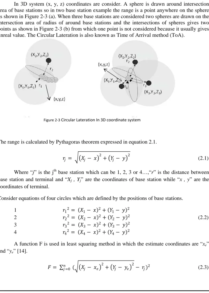
(22) Potential of existing UMTS signaling data for cell phone positioning. Master Thesis. Cellular Positioning. In 3D system (x, y, z) coordinates are consider. A sphere is drawn around intersection area of base stations so in two base station example the range is a point anywhere on the sphere as shown in Figure 2-3 (a). When three base stations are considered two spheres are drawn on the intersection area of radius of around base stations and the intersections of spheres gives two points as shown in Figure 2-3 (b) from which one point is not considered because it usually gives unreal value. The Circular Lateration is also known as Time of Arrival method (ToA).. Figure 2-3 Circular Lateration In 3D coordinate system. The range is calculated by Pythagoras theorem expressed in equation 2.1. 2. 𝑟𝑟𝑗𝑗 = ��𝑋𝑋𝑗𝑗 − 𝑥𝑥� + �𝑌𝑌𝑗𝑗 − 𝑦𝑦�. 2. (2.1). Where “j” is the jth base station which can be 1, 2, 3 or 4…,“r” is the distance between base station and terminal and “Xj , Yj” are the coordinates of base station while “x , y” are the coordinates of terminal. Consider equations of four circles which are defined by the positions of base stations. 1 2 3 4. 𝑟𝑟1 2 = 𝑟𝑟2 2 = 𝑟𝑟3 2 = 𝑟𝑟4 2 =. (𝑋𝑋1 − (𝑋𝑋2 − (𝑋𝑋3 − (𝑋𝑋4 −. 𝑥𝑥)2 + (𝑌𝑌1 − 𝑥𝑥)2 + (𝑌𝑌2 − 𝑥𝑥)2 + (𝑌𝑌3 − 𝑥𝑥)2 + (𝑌𝑌4 −. 𝑦𝑦)2 𝑦𝑦)2 𝑦𝑦)2 𝑦𝑦)2. (2.2). A function F is used in least squaring method in which the estimate coordinates are “xe” and “ye” [14]. 2. 2. 𝐹𝐹 = ∑𝑛𝑛𝑗𝑗 =0 (��𝑋𝑋𝑗𝑗 − 𝑥𝑥𝑒𝑒 � + �𝑌𝑌𝑗𝑗 − 𝑦𝑦𝑒𝑒 � − 𝑟𝑟𝑗𝑗 )2. (2.3). 9.
(23) Master Thesis. Cellular Positioning. Potential of existing UMTS signaling data for cell phone positioning. Expand equation 2.2 and subtract the 2, 3, 4 from 1. New equations are formed as equation (2.4) 1 2 3. (𝑋𝑋1 − 𝑋𝑋2 )𝑥𝑥𝑒𝑒 + (𝑌𝑌1 − 𝑌𝑌2 )𝑦𝑦𝑒𝑒 = (𝑋𝑋1 − 𝑋𝑋3 )𝑥𝑥𝑒𝑒 + (𝑌𝑌1 − 𝑌𝑌3 )𝑦𝑦𝑒𝑒 = (𝑋𝑋1 − 𝑋𝑋4 )𝑥𝑥𝑒𝑒 + (𝑌𝑌1 − 𝑌𝑌4 )𝑦𝑦𝑒𝑒 =. 1 2 1 2 1 2. �𝑋𝑋1 2 − 𝑋𝑋2 2 + 𝑌𝑌1 2 − 𝑌𝑌2 2 + 𝑟𝑟2 2 − 𝑟𝑟1 2 � �𝑋𝑋1 2 − 𝑋𝑋3 2 + 𝑌𝑌1 2 − 𝑌𝑌3 2 + 𝑟𝑟3 2 − 𝑟𝑟1 2 �. (2.4). �𝑋𝑋1 2 − 𝑋𝑋4 2 + 𝑌𝑌1 2 − 𝑌𝑌4 2 + 𝑟𝑟4 2 − 𝑟𝑟1 2 �. The equation 2.4 can be expressed in form of matrix as in equation 2.5 𝐴𝐴. 𝑃𝑃𝑒𝑒 = 𝐵𝐵. Where,. 𝑋𝑋1 − 𝑋𝑋2 𝐴𝐴 = � 𝑋𝑋1 − 𝑋𝑋3 𝑋𝑋1 − 𝑋𝑋4. 𝑌𝑌1 − 𝑌𝑌2 𝑌𝑌1 − 𝑌𝑌3 � 𝑌𝑌1 − 𝑌𝑌4. 𝑋𝑋1 2 − 𝑋𝑋2 2 + 𝑌𝑌1 2 − 𝑌𝑌2 2 + 𝑟𝑟2 2 − 𝑟𝑟1 2 1 𝐵𝐵 = �𝑋𝑋1 2 − 𝑋𝑋3 2 + 𝑌𝑌1 2 − 𝑌𝑌3 2 + 𝑟𝑟3 2 − 𝑟𝑟1 2 � 2 𝑋𝑋1 2 − 𝑋𝑋4 2 + 𝑌𝑌1 2 − 𝑌𝑌4 2 + 𝑟𝑟4 2 − 𝑟𝑟1 2 𝑥𝑥𝑒𝑒 𝑃𝑃𝑒𝑒 = �𝑦𝑦 � 𝑒𝑒. (2.5). (2.6). (2.7). (2.8). To calculate Pe equation 2.5 can be written as, 𝑃𝑃𝑒𝑒 = (𝐴𝐴𝑇𝑇 . 𝐴𝐴)−1 . 𝐴𝐴𝑇𝑇 . 𝐵𝐵. (2.9). The estimation position of terminal is calculated by using the equation 2.9 The GPS is best example of this ToA technique in which GPS receives information from three satellites and calculate its position where forth satellite is used for clock synchronization.. 2.6.2.2 Hyperbolic Lateration In hyperbolic lateration, positioning is calculated on difference on range measurements. In the hyperbola all the points have constant range difference from two base stations as shown in Figure 2-4 . For 2D coordinate system if the target is calculated from two base stations a hyperbola is formed on all points which are equal distance from base stations as in Figure 2-4 (a). When three base stations are in range of target then hyperbola is made which give a constant point as shown in Figure 2-4 (b).. 10.
(24) Potential of existing UMTS signaling data for cell phone positioning. Master Thesis. Cellular Positioning. Figure 2-4 Hyperbolic Lateration ((a) and (b) are for two and three base station respectively). The difference in the range is calculated by equation (2.10). 𝐷𝐷𝑖𝑖𝑖𝑖 = 𝑟𝑟𝑖𝑖 − 𝑟𝑟𝑗𝑗. (2.10) 2. 2. 𝐷𝐷𝑖𝑖𝑖𝑖 = �(𝑋𝑋𝑖𝑖 − 𝑥𝑥𝑒𝑒 )2 + (𝑌𝑌𝑖𝑖 − 𝑦𝑦𝑒𝑒 )2 + (𝑍𝑍𝑖𝑖 − 𝑧𝑧𝑒𝑒 )2 − ��𝑋𝑋𝑗𝑗 − 𝑥𝑥𝑒𝑒 � + �𝑌𝑌𝑗𝑗 − 𝑦𝑦𝑒𝑒 � + �𝑍𝑍𝑗𝑗 − 𝑧𝑧𝑒𝑒 �. 2. Where, “i” and “j” are the base stations, “Dij” is the difference between ranges “ri” and “rj” of the “ith” and “jth” base stations and (X, Y, Z) are coordinates of base stations and (xe, ye, ze) are estimated coordinates of the terminal. To solve the system, for nonlinear equation, is same as for circular lateration. A Taylor series is made on the basis of estimated fixed of the terminal position [7] which produces the equations given below. 𝜕𝜕𝜕𝜕 𝑖𝑖𝑖𝑖 𝜕𝜕 𝑥𝑥 𝑒𝑒. 𝜕𝜕𝜕𝜕 𝑖𝑖𝑖𝑖 𝜕𝜕 𝑦𝑦 𝑒𝑒. 𝜕𝜕𝜕𝜕 𝑖𝑖𝑖𝑖 𝜕𝜕 𝑧𝑧 𝑒𝑒. = = =. −𝑋𝑋 𝑖𝑖 + 𝑥𝑥 𝑒𝑒 𝑟𝑟 𝑖𝑖. −𝑌𝑌𝑖𝑖 + 𝑦𝑦𝑒𝑒 𝑟𝑟 𝑖𝑖. −𝑍𝑍𝑖𝑖 + 𝑧𝑧𝑒𝑒 𝑟𝑟 𝑖𝑖. −. −. −. −𝑋𝑋 𝑗𝑗 + 𝑥𝑥 𝑒𝑒 𝑟𝑟 𝑗𝑗. −𝑌𝑌𝑗𝑗 + 𝑦𝑦𝑒𝑒 𝑟𝑟 𝑗𝑗. −𝑍𝑍𝑗𝑗 + 𝑧𝑧𝑒𝑒 𝑟𝑟 𝑗𝑗. = 𝑎𝑎𝑖𝑖. = 𝑏𝑏𝑖𝑖. (2.11). = 𝑐𝑐𝑖𝑖. 11.
(25) Master Thesis. Cellular Positioning. Potential of existing UMTS signaling data for cell phone positioning. The matrix “A” of the resulting system of linear equations is made by using coefficients “ai”, “bi”, “ci”, and vector “B” is made by using the deviation of observed pseudorange from estimated position range [7]. By using the equation 2.5 the estimated position can be determined. This hyperbolic Lateration is also known as Time Difference of Arrival method (TDoA) and it is normally used by cellular operators for estimating the position of users. The accuracy can be improved by using advanced methods which are considered complex with respect to Cell-ID and TA. Time of Arrival (ToA), Enhanced observed Time Difference (E-OTD) and Observed Time Difference of Arrival (OTDA) are examples of these methods. These methods cannot rely on legacy network and UE because these methods need to install new hardware called as Location Measurement Units as it requires extra signaling for estimation of position. These methods based on propagation of time delay between UE and three Base Stations, which must be in service with the UE but even these advanced methods are facing serious difficulties in locating the position of UE one of these are NLOS problem. In [9] simulation is performed to measure the position accuracy for ToA method in WCDMA, 16 and 48 measurements are used for positions of UE. When 300 random UE positions are selected then it gives CEP 67% in 125m for urban environment and CEP 67% in 50m for suburban environments. The positioning accuracy of suburban environments is better due to less multi path propagation in suburban environment. The simulation on TDoA is performed in [10] on WCDMA and CDMA2000. For WCDMA the coherent integration is doubled in this simulation environment and it is concluded that CEP 67% in 100m for urban environment.. 2.6.3 Angulation Angulation is also a technique which is used to find the position of terminal in cellular networks. In this method the position is calculated by observing the angel between base stations and UE, this method is also known as Direction of Arrival (DoA) or Angle of Arrival (AoA). The drawback for this positioning method is that it is required that handset or base station should be equipped with antenna arrays. For handset assisted position it is required that handset are equipped with antenna arrays while for network base positioning base station should be equipped with antenna arrays. It is more convenient that network used antenna array system because it is easy to install on network side instead of installing on every handset. Angle of signal from base station to terminal is drawn for one base station and similarly for another base station so the intersection point is the location of terminal as shown Figure 2-5.. 12.
(26) Master Thesis. Cellular Positioning. Potential of existing UMTS signaling data for cell phone positioning. Termina Base Station. α1 (X1, Y1). α2 (X2, Y2) Figure 2-5 Angulation. The angulation have also the error due to multipath propagation, as in multipath the signal is reflected from different objects so, there may be error to estimate the correct direction. So, it is required to consider the pilot signal from more than two base stations so in this way the probability of error can be reduced. The angle (ϕ) may have error (ε) so the actual angle (α) is calculated by equation 2.12 α= ϕ+ ε. (2.12). The angle from base station jth is calculated as αj = arctan �. Yj − y. ϕj = arctan �. Yj − y. Xj − x. �. (2.13). Where (Xj, Yj) and (x, y) are the coordinates of base stations and terminals respectively. As the angles are not exactly known, an approximation is made by least square fit that starts with linear equation using Taylor series expansion. The observed angle is expressed by ϕ of estimated position and a correction vector [7].. Xj − x. �. ϕj = ϕj (xe + △ x, ye + △ y). (2.14). The partial differences of Taylor series expansion are given by equation 2.15. dϕj xe dϕj ye. =. sin ϕj = rj cos ϕj. = −. rj. aj. = bj. (2.15). 13.
(27) Master Thesis. Cellular Positioning. Potential of existing UMTS signaling data for cell phone positioning. Where, “rj” is the range between terminal and base station “j”. The matrix A of the resulting system of linear equations is made by using coefficients “aj” and “bj”, and by using the angle difference between the observed angle and the angle derived from the estimated position the vector B can be made [7]. By using the equation 2.5 the estimated position can be determined. In [11] AoA and TDoA positions techniques are estimated for WCDMA system. It is noted that root mean square error (RMSE) in meter is less in TDoA as compared to AoA with constant Signal to Noise (SNR) value. The RMSE is 100m for TDoA and 125m for AoA.. 2.6.4 Data Base Correlation Method Database Correlation Method (DCM) is commonly used method for positioning because it has the ability to accommodate the legacy terminals, it is also known as Pattern Matching and Fingerprinting. In this method a database is created which helps to find the position of UE. Database correlation method can overcome different problems like no line of sight, shadowing and multipath effects. In DCM the position can be estimated by measurements made by Base Station or by UE or from both and these measurements then compared with the already stored data base and best matching result will be estimated as the required position. It is divided into two types. • •. Non-RSS Based RSS Based. The main principle of Non-RSS is matching of optical patterns, in which the images are taken and compared with each other. It is further divided into two categories. o Static Pattern o Dynamic Pattern In Static pattern matching the position is located by comparing the observed images with the stored images, while in dynamic pattern matching the position is located as the difference in the images of consecutive locations. The main principle of DCM is correlation or matching and it is also known as fingerprinting. Fingerprinting is done in two steps, collection of data and matching. In collection of data mode the data is collected by measuring the RSS values and other required parameters at each point, these values will be stored in database and known as fingerprints. In matching mode, when the terminal reports the RSS and other measurement values of current location, it is searched and matched with the values stored in database and by using some algorithm the required position can be estimated. In UMTS system UE transmits its values to Node B and Node B sends this information to the core network where the matching algorithm works to. 14.
(28) Master Thesis. Cellular Positioning. Potential of existing UMTS signaling data for cell phone positioning. estimate the position of the UE by matching the received values to the values stored in Data Base. This whole process is done in following steps • •. Collection of Database Matching. 2.6.4.1 Collection of Database Collection of database is one of the necessary and important steps as all other calculations, to locate the position of UE, are based on this database. Fingerprint values can be collected/calculated in following three ways • • •. Using Test Drive information Using Propagation Model Estimation (Prediction) Hybrid. Test drive is most commonly used method for data collection. In which the mobile hand set connected with the TEMS (Ericsson data investigation tool), used in this thesis, and the hand set will be derived in the test area i.e., streets, roads, open grounds, markets etc. TEMS investigates the data and measured the RSS value for each point along with coordinates and this data is then stored in the database as fingerprints which will be used in the second step for matching. This method of collecting data at particular area is easy because there is no need to apply different prediction methods to get RSS values but to use test drive method for every point in that area is time consuming. So, to make the test drive data more denser, estimation techniques can be applied like propagation models estimations or prediction estimations [12][13]. In wave propagation model one base station at a time is used to calculate a propagation prediction which helps in analyzing the scenario and interferences around. There are many different propagation models developed to fulfill the requirements in recent years like COST 231, Hata-Okumura, Walfisch-Ikegami and Petersen Knife Edge. In[15] COST 231 semi-deterministic model is used, which is the base for predictions in urban areas based on Extended Walfisch-Ikegami Model, in which wave propagation is considered over the roof tops. Hata-Okumura’s empirical model is the base for prediction in rural areas and diffraction losses are introduced in empirical model by using Petersen Knife Edge Model, which actually introduces obstacles between receiver and transmitter, discussed in detail in [16]. With the help of these prediction models a LUT can be constructed for path loss and propagation time values which help in predicting the values.. 15.
(29) Master Thesis. Cellular Positioning. Potential of existing UMTS signaling data for cell phone positioning. Hybrid method is the way to make the database by using combine values of drive test method and propagation predictions. In this method drive test is used to get values for some points and the points which cannot be covered in drive test their values can be predicted by using different estimation techniques as used in [12][13][15].. 2.6.4.2 Matching When it is needed to estimate the position of particular UE, it sends its measurement values to serving site and network compares its values with the fingerprint values stored in database. The position can be estimated by using some algorithm like, Euclidean distance or Bayesian Inference Location Method. Let us consider first the Euclidean distance which can be simply written in mathematical form as Euclidean distance = 𝑑𝑑𝑘𝑘𝐸𝐸𝐸𝐸 Where,. = �∑𝑖𝑖∈𝑀𝑀 (𝑓𝑓𝑘𝑘𝑘𝑘 − 𝑚𝑚𝑖𝑖 )2. (2.16). 𝑑𝑑𝑘𝑘𝐸𝐸𝐸𝐸 = Euclidean distance for fingerprint k. fki = RSS for scrambling code “i” in fingerprint “k” fki = 0 if scrambling code “i” is not available in fingerprint “k” mi = RSS for scrambling code “i” in measurement M = set of scrambling code in measurement Consider an example as shown in Figure 2-6, it is needed to locate the position of UE in that area. Circles in Figure 2-6 shows database fingerprints, star shows the Node B and filled square shows the position of UE. To locate the position of UE, first of all the UE reports the measurements of all the hearable Node B’s to network. Then difference is calculated between fingerprint values of database and measurement values by using Euclidean distance. Consider four Node Bs in range of UE and UE is observing different RSS values from these four Node Bs, which it reports to the network, and network calculates the differences at each fingerprint. The position can be estimated with smallest difference as the required position but the accuracy can be improved by taking average of corresponding location coordinates of smallest differences obtained. So, by taking average of coordinates of smallest differences the position of UE can be estimated, where average depends on density of database values.. 16.
(30) Master Thesis. Cellular Positioning. Potential of existing UMTS signaling data for cell phone positioning. Figure 2-6 Estimating position using nearest neighbor. In [15] matching algorithm is made by using two approaches Least Mean Square (LMS), which is based on Euclidean distance, and Exponential (EXP), mathematical expressions are shown in [15] where score is represented by “SLMS and SEXP”. In case of LMS, the best matching location will be that which has minimum score value and in case of EXP, the best matching location will be that which has maximum score value [15]. There is another method, Bayesian Inference RSS Location Method, to locate the position of the UE. In this method an unknown position of the UE can be found by using the likelihood function of the locations, given the measurements. In first phase the signal strength data is collected at reference positions. After collection of database, during estimation phase the probability distribution is computed for received signal strength for each database point, where database point is considered as reference position. During estimation the point with highest probability is considered to be the required position of UE. During initial survey the data is collected for each reference point as given below. 𝑠𝑠𝑐𝑐 = (𝑥𝑥𝑐𝑐 𝑦𝑦𝑐𝑐 𝑝𝑝𝑐𝑐 )𝑇𝑇. (2.17). 𝑆𝑆 = {𝑠𝑠1 𝑠𝑠2 𝑠𝑠3 … 𝑠𝑠𝑐𝑐 … 𝑠𝑠K }. (2.18). Where (xc , yc ) is two dimensional coordinates of particular location and pc is the orientation of targeted UE. There are total K numbers of states so, total number of surveys can be written as. Where K = number of survey locations × number of orientations (𝑝𝑝𝑐𝑐 ) 17.
(31) Master Thesis. Cellular Positioning. Potential of existing UMTS signaling data for cell phone positioning. The measurement sets, during the database creation phase, are taken from each of the position states. These measurements are of signal strength noted at each Node B in range and these measurement sets are identified with the state vector and set of each measurement is known as observation “o”, which can be represented as: 𝑜𝑜𝑐𝑐 = {(𝜎𝜎1 , 𝑎𝑎1 ), (𝜎𝜎2 , 𝑎𝑎2 ), … (𝜎𝜎𝑀𝑀 , 𝑎𝑎𝑀𝑀 )}. (2.19). Where oc is the observation at each state and σ1 , σ2 , σ3 … σM are signal strength for Node B which can be represented as σi , where “i” = 1, 2, 3…M and a1 , a2 , a3 … aM are the addresses of the Node B, which are normally known as Node B ID. So, the probability that when the user was at position sc the observation “o′ ” was taken can be find by using Bayesian rule. Where “o′ ” is the real-time observation made by the target. ′. 𝑃𝑃�𝑜𝑜 ′ �𝑠𝑠𝑐𝑐 �𝑃𝑃(𝑠𝑠𝑐𝑐 ). 𝑃𝑃(𝑠𝑠𝑘𝑘 |𝑜𝑜 ) = ∑𝐾𝐾. ′ 𝑐𝑐=1 𝑃𝑃(𝑜𝑜 |𝑠𝑠𝑐𝑐 )𝑃𝑃(𝑠𝑠𝑐𝑐 ). (2.20). Where P(o′ |sc ), the conditional probability is obtained from survey by making statistics and P(sc )is the weighting probability and is equal to1⁄K. This expression will give posteriori probability for the user that the observation was made when the UE was in state sc . Similarly the probability for all states will be made and the state for which the maximum probability is obtained considered being the most likely position.. 18.
(32) Master Thesis. UMTS Location Data. Potential of existing UMTS signaling data for cell phone positioning. Chapter 3 -UMTS Location Data The Universal Mobile Telecommunications System (UMTS) is considered to be the 3G (3rd generation) communication system which provides a wide range of broadband services on the go during mobility. It is designed to cope with the problems in providing internet services with better data rate. In order to go in more detail for location based services in UMTS firstly, need to know its structure in brief so, this chapter presents UMTS structure specified by 3GPP, main network elements related to Location based services, radio management, mobility management and basic signaling information used for finding position to provide location based services. The first version of UMTS was specified in 3GPP Release 99, in which most of the functionality of GSM/GPRS was adopted with introduction of new technology to access wireless network, named as Wideband Code Division Multiple Access (WCDMA). This access technique increased the data rate and enhanced the 2G system capacity. Further 3GPP releases, Release 4 and Release5/6, introduced a new platform, the IP Multimedia Subsystem (IMS), which makes it possible to migrate from conventional Circuit-Switched domain to IP-based Packet-Switched domain.. 3.1. UMTS Architecture. The basic network architecture of UMTS is shown in Figure 3-1 with its main logical network elements which are connected with each other through radio interfaces. The UMTS network is divided in to two main parts a core network, which handles circuit switched (CS) domain and packet switched (PS) domain, and UMTS Terrestrial radio access network (UTRAN) which handles all radio related functions. Finally the user equipment (UE) is the element which completes the system and it is a 3G enabled terminal.. 3.1.1 UTRAN UTRAN is subdivided into RNSs and one UTRAN can consist of more than one RNS and each RNS is controlled by RNC and each RNC is further connected with Node B which can also be more than one. RNC is the main controlling element of UTRAN which is connected with Node B through interface Iub and with other RNC through Iur. Node B is physical transceiver unit in cells and its main responsibility is to receive and transmit data to and from UE with which it is connect through Uu interface.. 19.
(33) Master Thesis. UMTS Location Data. Potential of existing UMTS signaling data for cell phone positioning. 3.1.2 Core Network (CN) UTRAN is connected with core network (CN) through Iu interface and on basis of data type CN is divided into two parts Circuit Switched domain which handles the circuit switched calls mainly voice calls and Packet Switched domain which handles packet data. In CS domain the main entities which play role to control the communication are MSC and GMSC and in PS domain SGSN and GGSN are the main entities which control the data communication.. Figure 3-1 Basic Network Architecture of UMTS (3G network). 3.2. UMTS Data for Positioning. The accuracy of positioning of UE is based on the available measurements and most of the information in measurements is available at the time of active call. The positioning can be made at user side where user equipment (UE) needs to calculate the position and send it to the network but this thesis is to deal with the positioning based on network in which UE will send the measurement reports to network and then network locates the position of the device. In this thesis the mostly used data information is based on Layer 3 messages at uplink DCCH (ULDCCH). UMTS Layers are set of rules or protocols for communication which need to be followed to execute and complete the network functions in a coordinated manner. There are three UMTS layers named as Transport Network Layer, Radio Network Layer and System Network Layer.. 20.
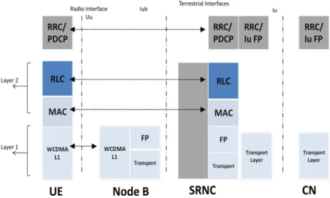
(34) Master Thesis. UMTS Location Data. Potential of existing UMTS signaling data for cell phone positioning. 3.2.1 Transport Network Layer In UMTS protocol architecture the Transport Network Layer is the lowest layer and it connects Node B with RNC. The Transport network Layer is divided in to further two layers commonly known as L1 and L2. L1 is called as physical layer and L2 is called data link layer where L1 is based on WCDMA radio technology. Transport channels are responsible for carrying the data, which is generated at higher layers, over air interface and these transport channels are actually mapped on physical channels in the physical layer and physical layer is responsible to carry the data to destination. The transport channels are of two types in respect of resources used: • •. Dedicated channel (DCH) Common channel (CCH). For the users who are using dedicated resources will be treated by the dedicated channels and a single user is allotted by a dedicated channel while in common channel, resources are divided in a group of users who will share these resources by using common channel. The transport channels defined in WCDMA are Broadcast Channel (BCH), Forward Access Channel (FACH), Paging Channel (PCH), Random Access Channel (RACH) and Dedicated Channel (DCH) from these first three are downlink common channels and RACH is uplink channel and DCH is used for both uplink and downlink.. Figure 3-2 Transport Network Layer Protocol. Over Uu interface the L2 works with two link protocols named as Medium Access Control protocol (MAC) and Radio Link control protocol (RLC). MAC characterizes the data and then its responsibility is to work with logical channels by mapping them accordingly. The responsibility of RLC is to provide data into the form of RLC payload units which will be error. 21.
(35) Master Thesis. UMTS Location Data. Potential of existing UMTS signaling data for cell phone positioning. free and this can be done by segmentation of data, which is in variable length, and this error free connection is possible because of the availability of retransmission of the packet. Some of the functions of MAC layer are: • Characterizing the data • Prioritizing the data flows • Prioritizing the users • Scheduling of different messages i.e. broadcast, paging and notification messages • Identification of subscribers on common control channel • Multiplexing of PDUs of higher layer and de-multiplexing Some of the functions of RLC are: • Control of connection • Segmentation and de-segmentation • User data transfer • Correction of error • Retransmission of dropped packet • Flow control • Ciphering. 3.2.2 Radio Network Layer Radio network layer is commonly known as L3 and is on the top of Transport Network layer. RF Network protocol has its impact across the network from UE to CN. RF Network protocol can be classified in two planes • •. Radio Network Control Plane Radio Network User Plane. Radio network user plane, using the control information and radio access bearers established by the control plane, transfers the user data. The main responsibility of Radio network control plane is to handle the controlling functions and manages other functions like radio access bearers. All of the four interfaces, Uu, Iub, Iur and Iu, contain UTRAN-specific control protocols. The Radio Resource Control (RRC) protocol also works at this plane and its main function is to handle and manage the radio resource for user traffic. RRC also handles the mobility of the user equipment in active call mode by getting measurement reports from user equipment. In active mode when user is moving it needs to remain connected and network continuously needs measurement reports from the user equipment which contains information which helps the network to assist the user equipment. These measurement reports are actually the messages at RRC protocol which contains information of the current active set and neighboring monitors with their parameter as given below:. 22.
(36) Master Thesis. UMTS Location Data • • •. • • • •. Potential of existing UMTS signaling data for cell phone positioning. Mode Specific Information Off = Number of frames with range of 0 to 255 Tm = TRxSFNi – TRxSFNi o TRxSFNi = Time of received neighboring P-CCPCH form cell j at its beginning o TRxSFNi = Time of received serving P-CCPCH form cell i at its beginning Scrambling Code information Ec-N0 in dB RSCP in dBm SFN-SFN OTD. Using information of Tm and Off, SFN-SFN OTD can be calculated in chips as: 𝑆𝑆𝑆𝑆𝑆𝑆 − 𝑆𝑆𝑆𝑆𝑆𝑆 = 𝑂𝑂𝑂𝑂𝑂𝑂 × 38400 + 𝑇𝑇𝑚𝑚. 3.2.3 System Network Layer. System network layer works on the top of Radio network layer and it is system network protocol which creates communication services to the users. System network protocol transparently operates through radio access. System network layer can be further divided in to sub layers. Session layer provides the service specific session for which Communication Management protocol (CM) is responsible. The lower Mobility Management sub layer provides the services for mobility over the radio network, which provides signaling connection. IP based transport and application layers operate on the top of UMTS Network layer.. Figure 3-3 System network layer. 23.
(37) Master Thesis. UMTS Location Data. 3.3. Potential of existing UMTS signaling data for cell phone positioning. Radio Resource Management. UMTS provides high flexibility in allocating the resources but this flexibility needs to be designed with good management strategies in such a way that the resources can be used effectively in the system. With use of better strategies for resource management, resources can be controlled and maintained properly like power control, load control, admission control and handover control [20]. RRM algorithms are carried out in RNC for UMTS architecture [21]. The main purpose of positioning of cell phone is to provide location based services and these services require high data rate and due to this there will be more traffic and more power consumption, for all these RRM played an important role in managing the resources and providing high data rate services with better QoS to multiple users and at the same time also controls the running services at the time of handovers. RRM works in two phases [19] • •. Radio resource configuration Radio resource re-configuration. Where in first phase the responsibility is to accommodate new requests and allocate proper resources without overloading the system but congestion may occur and cause effects on QoS. In second phase the responsibility is to re-accommodate the requests to allocate the resources when congestion starts or when load build up. In this way QoS remains at suitable level and at the same time resources are arranged in proper way for all running various applications. So, RRM plays very essential and vital role in managing the available resources for different services between multiple users and it also makes it possible to continue the running services without any breakdown.. 3.3.1 Main objective of RRM The main objective of RRM is to provide services without any breakdown with high QoS with manageable resources. As UMTS can offer number of different types of services in which some are high sensitive to delay and some are high sensitive to BER and some are high sensitive to both, so, the main objective of RRM is to allocate resources by knowing the sensitivity of the service. For the services, which require high data rate and are medium sensitive to delay, RRM should manage it by providing high data rate and can save power when it concerns with delay. Similarly if a service which is no sensitive to delay but high sensitive to BER like background services, then RRM can manage resources accordingly by saving bandwidth. In UMTS network RRM can offer maximum performance, high QoS and optimize the system capacity by using the knowledge of type of service. So, the main objectives of RRM are: • •. Offer more capacity in coverage area Provides high QoS according to type of services. 24.
(38) Master Thesis. UMTS Location Data •. Potential of existing UMTS signaling data for cell phone positioning. Proper Usage of Radio resource to cover a required area. There are four main and basic types of services which UMTS has to provide [19] with high QoS and these are: 1) 2) 3) 4). Real time voice calls Streaming services Interactive services Background services. From the above mentioned services voice calls are very sensitive to delay and jitter, streaming is medium sensitive to delay but high sensitive to jitter, interactive services are also sensitive to delay but to some extent and high sensitive to BER.. 3.3.2 Functions of RRM There are three main functions of RRM which play an important role in managing resources and provide high QoS to multiple users. Following are the three main functions of RRM: • • •. Power control Handover control Congestion control. 3.3.2.1 Power control Out of the above mentioned three functions power control is the most critical and important function because of near-far-effect. As in WCDMA, contrary to GSM, every user use same frequency due to which interference becomes a crucial issue because in uplink transmission if UE is transmitting with high power at closer distance to Node B then it over shouts the other UEs signals which are at more distance due to which the whole cell may be blocked. Similarly, when UE is transmitting with the very lower power then it might not be heard by the Node B. So, this function makes it possible to transmit signal at the minimum required power level and to ensure that it meets the required QoS at the receiving end. So, in short power control function of RRM provides minimum required power to the user equipment which makes it possible to overcome near-far effect and controls the interference which also helps in optimizing the battery life of the user equipment.. 25.
Figure


+7


Related documents
Byggstarten i maj 2020 av Lalandia och 440 nya fritidshus i Søndervig är således resultatet av 14 års ansträngningar från en lång rad lokala och nationella aktörer och ett
Omvendt er projektet ikke blevet forsinket af klager mv., som det potentielt kunne have været, fordi det danske plan- og reguleringssystem er indrettet til at afværge
I Team Finlands nätverksliknande struktur betonas strävan till samarbete mellan den nationella och lokala nivån och sektorexpertis för att locka investeringar till Finland.. För
För att uppskatta den totala effekten av reformerna måste dock hänsyn tas till såväl samt- liga priseffekter som sammansättningseffekter, till följd av ökad försäljningsandel
Syftet eller förväntan med denna rapport är inte heller att kunna ”mäta” effekter kvantita- tivt, utan att med huvudsakligt fokus på output och resultat i eller från
Generella styrmedel kan ha varit mindre verksamma än man har trott De generella styrmedlen, till skillnad från de specifika styrmedlen, har kommit att användas i större
I regleringsbrevet för 2014 uppdrog Regeringen åt Tillväxtanalys att ”föreslå mätmetoder och indikatorer som kan användas vid utvärdering av de samhällsekonomiska effekterna av
defines the aim of the thesis and solution methods. The main task is the diagnostics of low-speed bearings by the sprocket shaft bearing assembly including the design
