MODULAR FRICTION TEST RIG FOR
MEASURING TORQUE AND TENSION
IN THREADED FASTENERS
Reza Afsharian
Antonios Theodoropoulos
Master of Science Thesis TRITA-ITM-EX 2018:620 KTH Industrial Engineering and Management
Machine Design SE-100 44 STOCKHOLM
Examensarbete TRITA-ITM-EX 2018:620
Modulär friktionsrigg för mätning av moment och töjning i gängade fästelement
Reza Afsharian Antonios Theodoropoulos Godkänt 2018-08-29 Examinator Ulf Sellgren Handledare Sergei Glavatskih Uppdragsgivare
Atlas Copco Industrial Technique AB, R&D
Kontaktperson
Erik Persson
SAMMANFATTNING
Denna rapport beskriver utvecklingen av en modulär friktionsprovrigg för gängade fästelement. Den utvecklade enheten kan mäta moment och klämkraft under åtdragning av gängade skruvar, med en storlek mellan M3 och M14 och klämlängd på 30-160mm. Designen möjliggör användning av flera last- och vridmomentceller och intervallet är upp till 100kN klämbelastning och 200Nm påfört vridmoment. Provriggen är en forskningsrigg, och den kommer att användas av Atlas Copco för att bestämma friktionsegenskaperna i åtdragning och möjliggöra experiment på skruvar av olika material, och med olika ytbeläggningar och ytbehandlingar.
Denna rapport avslutas med ett designförslag, som utvärderas analytiskt och testprincipen demonstreras med hjälp av en prototyp. Mätningarna tas från skräddarsydda sensorer, som kan kalibreras individuellt och som är enkelt utbytbara. Dessutom är en anordning utvecklad för att tillåta användaren att ändra styvheten hos förbandet. Slutligen ges en rekommendation för en vidareutveckling, som möjliggör mätning av skallmomentet. Detta förslag är ett genombrott jämfört med andra existerande testriggar, och kommer att bidra till att verifiera friktionsmätningarna med hög precision.
Master of Science Thesis TRITA-ITM-EX 2018:620 Modular friction test rig for measuring torque and tension
in threaded fasteners Reza Afsharian Antonios Theodoropoulos Approved 2018-08-29 Examiner Ulf Sellgren Supervisor Sergei Glavatskih Commissioner
Atlas Copco Industrial Technique AB, R&D
Contact person
Erik Persson
ABSTRACT
This report describes the development of a modular friction test rig for threaded fasteners. This device can measure the shank torque and the clamp force during the tightening of threaded bolts, with a size of M3-M14 and clamp length of 30-160mm. The design allows the use of several load and torque cells and the range is up to 100kN clamp load and 200Nm applied torque. The test rig will be used for research purposes by Atlas Copco to determine the frictional characteristics in tightening and will allow the experiments on bolts with several materials, coatings and surface finishes.
This report concludes to a design proposal evaluated with analytical methods and a prototype 3D model that demonstrate the working principle of the test rig. The measurements are taken from custom-made sensors that are developed with high standards, are easily interchangeable and can be calibrated individually. In addition, a device is developed to allow the user to change the stiffness of the joint. Finally, a future recommendation is made to allow the measurement of the under-head torque. This proposal is a breakthrough compared to other test rigs, and will assist in verifying the friction measurements and having high precision results.
ACKNOWLEDGEMENTS
This thesis report concludes R. Afsharian’ and A. Theodoropoulos’ master thesis in Engineering Design at KTH Royal Institute of Technology. We would like to express our gratitude to the R&D Tightening Technique team at Atlas Copco Industrial Technique AB, for welcoming us into their group and providing a pleasant working environment throughout the thesis project.
We would like to thank our supervisors at Atlas Copco, Erik Persson and Mayank Kumar, for all their guidance and support throughout the project. All our fruitful discussions were an important source of inspiration that contributed in making this thesis a reality. We would further like to express our acknowledgement to our supervisor at KTH, Prof. Sergei Glavatskih, for his assistance and cooperation throughout the project and the help of Moritz Ploss who assisted us for the bearing friction experiment.
Reza Afsharian, Antonios Theodoropoulos Stockholm, August 2018
NOMENCLATURE
All units are in SI unless otherwise stated.Symbol
Description
𝐴𝐴 Bolt cross section area (tensile stress area) 𝐶𝐶𝐿𝐿 Guide strip length
𝑑𝑑 Bolt nominal diameter
𝑑𝑑𝑚𝑚 Equivalent diameter of the friction between the threads
𝑑𝑑𝑏𝑏 Equivalent diameter of the friction under the head of the bolt
𝑑𝑑𝐺𝐺 Guide strip groove diameter
𝐸𝐸 Young´s modulus
𝐹𝐹 Clamp Force
𝐹𝐹ℎ Horizontal forces acting on the thread
𝐹𝐹𝑡𝑡 Horizontal tightening force acting on the thread
𝐹𝐹𝑣𝑣 Vertical forces acting on the thread
ℎ The weld throat
𝑘𝑘𝑏𝑏 The axial stiffness of the bolt
𝑘𝑘𝑗𝑗 The stiffness of the joint
𝑘𝑘𝑡𝑡 Total stiffness of the bolt and joint assembly
𝑙𝑙 The weld length
𝐿𝐿 Clamp Length
𝑝𝑝 Thread pitch
𝑁𝑁 Normal force on the thread 𝑇𝑇𝑡𝑡𝑡𝑡𝑡𝑡 Total torque during tightening
𝑇𝑇𝑡𝑡ℎ Thread torque (thread friction torque + pitch torque)
𝑇𝑇𝑏𝑏 Bearing torque (friction torque under the head of the bolt)
𝑇𝑇𝑝𝑝 Pitch torque, i.e. the torque required for elongation of the bolt
𝑡𝑡𝐺𝐺 Guide strip thickness
𝛼𝛼 Flank angle [deg]
𝜃𝜃 Tightening angle [deg]
𝜑𝜑 Angle of friction [deg] 𝜆𝜆 Thread helix angle [deg] 𝜇𝜇𝑡𝑡 Thread Friction coefficient
𝜇𝜇𝑏𝑏 Bearing Friction coefficient
𝛿𝛿𝑏𝑏 Deformation of the bolt under a certain clamp force
TABLE OF CONTENTS
SAMMANFATTNING 3 ABSTRACT 5 ACKNOWLEDGEMENTS 7 NOMENCLATURE 9 1 INTRODUCTION 13 1.1 Background 13 1.2 Purpose 141.3 Delimitations & Requirements 15
1.4 Methodology 16 2 FRAME OF REFERENCE 19 2.1 Tightening Technique 19 2.1.1 Torque-controlled Tightening 20 2.1.2 Angle-controlled tightening 20 2.1.3 Elongation-controlled Tightening 20 2.2 Joint Types 20 2.3 Friction Influence 20
2.3.1 Under-head Friction Torque 21
2.3.2 Thread Friction Torque 21
2.4 Methods of Force and Torque Measurements 23
2.4.1 Strain Gauge Load Cells 24
2.4.2 Strain Gauge Torque Cell 25
2.4.3 Piezoelectric Crystal Force Cells 25
2.4.4 Piezoelectric Crystal Torque Cells 26
2.4.5 Hydraulic Load Cell 26
2.4.6 Pneumatic Load Cell 27
2.4.7 Magnetoelastic Force Sensor 27
2.5 Combined Load & Torque Sensors 28
2.6 Crosstalk 28
2.7 Bearing Selection 29
2.7.1 Radial Bearings 30
2.7.2 Thrust Bearings 32
2.7.5 SKF model of bearing friction: 36
2.8 Tolerances 36
2.9 Existing Technology 37
2.9.1 TesT Friction Testing Machine 37
2.9.2 PCB Piezotronics Testing Machine 37
2.9.3 BLM Testing Machine 38 3 CONCEPT DEVELOPMENT 41 3.1 Nut-adaptor 41 3.1.1 Conceptual Design 42 3.1.2 Concept Evaluation 43 3.1.3 Detailed Design 44 3.2 Main Device 46 3.2.1 Conceptual Design 47 3.2.2 Concept Evaluation 50 3.2.3 Detailed Design 55 3.2.4 Working Principle 71
3.3 Stiffness Variation Device 73
3.3.1 Conceptual Design 73
3.3.2 Concept Evaluation 75
3.3.3 Detailed Design 76
3.4 Stiffness of the Clamp Joint 78
3.5 Prototyping 82
4 EXPERIMENTS & DESIGN VALIDATION 83
4.1 Validation of the design 83
4.2 Experimental validation 83
5 CONCLUSION 87
6 RESULTS & DISCUSSION 89
7 RECOMMENDATIONS AND FUTURE WORK 91
7.1 Accuracy & Tightening Speed 91
7.2 Stiffer Design 91
7.3 Thrust bearing 92
7.4 New torque cell and force cell 92
7.5 Under-head torque measurement 92
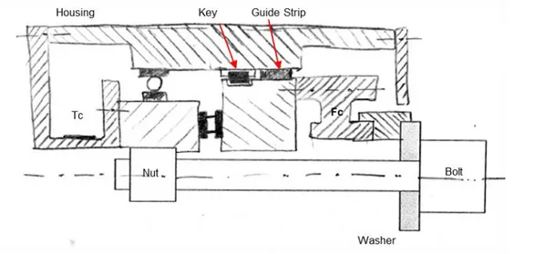
7.7 The Key 94
REFERENCES 95
APPENDIX A: STIFFNESS CALCULATION OF THE CLAMP JOINT 97
1 INTRODUCTION
This chapter describes the background, the purpose, the limitations and the method(s) used in the presented project.1.1 Background
There are several ways to join components together and by far the most common is to use a threaded fastener (screw) to clamp the joint members, either with a nut or a threaded hole in one of the components. This method is simple, low cost, provides easy mounting and can increase productivity. The screw consists of the shank and the head. The shank is fully or partly threaded, depending on the length of the screw. [1]
When tightening torque is applied on a screw, there can be multiple factors influencing the tension created. Such factors are the bulk properties of the materials in contact, their respective surface properties and treatment, and the magnitude of the actual physical contact. Out of them, the most principal factor is the variation in friction, since the pressure created and the material interfacing in contact surfaces may vary which results in variation of coefficient of friction. [2][3] The coefficient of friction is a dimensionless number, calculated from measured physical characteristics, which depends on the kind and on the geometry of the surfaces in contact. [2] A substantial proportion of the input torque, i.e. applied to the head of the fastener when tightening, is consumed by the frictional torque components. The first component is caused by the friction between the screw head and the joint, which is estimated approximately 50% of the applied torque and is called under-head friction torque or bearing friction torque. The second is caused by the friction in the threaded interfaces, which is estimated approximately 40% of the total torque and is called thread friction torque or shank torque. Finally, a smaller percentage, approximately the remaining 10 percent of the input torque, is responsible for the clamp force (Figure 1). This percentage causes the elongation and tension in the bolt that holds the clamp components together. This approximately 10% is the desired outcome of every tightening. [3]
Figure 1. Distribution of the Input Torque for a Fastener, source: PCB Load & Torque, [3]
The variation in friction will affect the torque components developed on the joint and sequentially the clamp force of it. When using torque as control parameter of the tightening (which is the most common way for tightening in industry), the clamp force is influenced more.
To aim for an accurate clamp force, it is important to measure friction between the screw head and joint, and in thread interfaces.
Figure 2. Drawing of a Bolted Joint, Oliver et al. (2006) [1]
The torque distribution between the frictional components and the clamp force depends on three factors: (1) the under-head and thread interface coefficient of friction, (2) the geometry of the joint and (3) material characteristics.
The research on this fields requires experiment of threaded fasteners with different friction coefficients (different coatings and materials), varied sizes (clamp length and bolt diameter), and fasteners of varied materials. The results will lead to gain deeper knowledge of friction characteristics when tightening, and how the dynamic/static friction relates to different coating/material and screw geometries. Understanding frictional phenomena will influence the quality of the assembly.
1.2 Purpose
The aim of this thesis project is to design, manufacture and verify a modular test rig which should conform to ISO 16047 [4] and the users’ requirements proposed by Atlas Copco, Industrial Technique. The test rig should take accurate and reliable measurements of the torque and clamp force in fasteners applications and have a modular design that allows varied sizes and materials to be tested in short time.
The thesis statement is defined as follows:
“Design, manufacture and verify a friction test rig for threaded fastener joints. The rig must be able to measure torque and force acting on the joint/screw. The torque and load cells shall individually be able to be calibrated at certified test institutes. The rig shall be able to test different screw sizes and clamp lengths. It shall be easy to use and easy to change screws between tests”.
This device is required as a research measurement instrument; thus, it shouldn't conform with customer regulations but to the researchers’ needs. The exact requirements are listed below, but beforehand the delimitations of the project are presented.
1.3 Delimitations & Requirements
This master thesis project is highly depending on the needs of the researchers that are working on tightening techniques at Atlas Copco Industrial Technique, Nacka. They have tested several devices, and they have deep knowledge on the working principles this device should have. Therefore, their needs are the fundamental non-measurable requirements of the project. After discussion the following delimitation and requirements have been set for the study:
• Measurement: Measure only torque in threads and clamp force of the threaded fastener. The device should be able to measure both the frictional torque in threads and the clamp force of the joint. The bearing torque will not be a point of interest as it can be calculated by formulas having other parameters.
• Crosstalk: The sensors should be uncoupled, which means that each measurement should act individually and not influence the other.
• Clamp-force-controlled tightening: There are several ways to control the tightening as stated below. For testing this device, the control parameter is the clamp force which is achieved by changing the nutrunner setup.
• Calibration: The torque/load cells are individually calibrated at certified test institutes. The device will accommodate two different measurement sensors (one for torque and one for load) that should be independent. Each sensor is calibrated individually.
• Bearing Friction: Bearings have friction both in axial and radial direction and may influence the results. The value of this friction will be analytically and experimentally calculated. A minimum accuracy limit will be set to optimize the results.
• Friction caused by the linear deformation of the joint: A key is used to fix the radial movement of the load cell. In case of axial micro movement in the system, there will be friction by the key. This friction is not taken in consideration for the force calculations, since it doesn’t affect the measurements.
• Error compensation: The final device has a measuring error caused by friction that cannot be fully defined. The friction range is estimated by experiments and an error compensation is future work.
• Low setup time: The device will be used to test many different threaded fasteners and coatings per day. The researchers want to do the experiments as fast as possible, thus the device should have low setup time.
• Easy to use: Since the researchers will test a lot of different fasteners, the device should be designed having taken in consideration the ergonomic aspects as well.
• One operator: One person should be able to monitor the entire device, change the setup and do the experiments. The test rig will have a horizontal configuration for easier setup.
• Tightening on the fastener: There are two ways of tightening the threaded fastener, by tightening the nut or by tightening the fastener. In the device to-be-developed the tightening will be on the fastener.
The thesis's requirements are based on ISO 16047 [3] and the users’ needs. ISO 16047 was published in 2005 and specifies the test method and conditions to quantify the tightening characteristics for threaded fasteners. It also gives some constraints that the testing device must satisfy. In addition, two different researchers who have experience in testing threaded fasteners were interviewed and their needs were translated to our systems requirements. Summing the previous inputs, the requirement list is presented below:
Requirements:
• Uncertainty: ±2% of the measured values
• Fastener size: M3-M14 • Clamp length: 30mm-200mm • Tightening Speed: 0-2000 rpm • Clamp Force: 5-100 kN • Shank Torque: 2-100 Nm • Total Torque: 5-200 Nm
• Required number of users: 1 person
• Set-up time: 20 sec
• Stiffness: Variation of stiffness equivalent to 30-180° tightening angle
• Modular Design: use 2 load cells and 2 torque cells of different range to increase accuracy
1.4 Methodology
The structure of the thesis work is presented in this section. This work couldn´t have been accomplished without precise project management and constant updates of the time schedule. The tasks were demanding and required good planning and execution. For the project management an online electronic tool was used to manage the deadlines and the milestones of the project. There were weekly meetings with the supervisor at KTH and daily conversation with the users at the company to identify the exact needs and requirements and in general the following design method was followed.
The first step was to identify the mission of the project. Why is this test rig important and how will that assist the research on the friction in the interfaces while tightening? To answer these questions an extended background research was made. Topics like friction, tightening, energy loss, control, crosstalk, bearings, sensor system were researched, and the founding’s are presented in the following report. After acquiring all the knowledge needed to move on, the conceptual design phase was entered. During this phase regular meetings, brainstorming activities, queries and many proposals were made to finalize the concept. The requirements kept evolving and after some changes to the initial model the final concept was decided. After that, the detailed design phase started. Analytical, experimental and computational means were used to test and verify each component and to make sure that everything works and fits together. Afterwards, the verification was done by manufacturing and testing step. The parts were sent to external suppliers and manufactured using different techniques. 3D-printers were also used to develop 3D prototypes and assist the visualization of the device and to develop some functional small parts as well. While waiting for the parts to be manufactured, future devices were developed to assist the user in conducting their experiments and are presented in additional work and future suggestions.
For the development of the measuring device, several tools and software were used. More specifically, the 3D model was accomplished using CREO parametric, the finite element analysis was conducted using ANSYS Academic and MATLAB was used for analytical calculations.
The outline of the report is presented below:
Chapter 1. In the beginning of this report, the background of the problem is presented, in addition to the delimitations, the requirements and the scope of this thesis.
Chapter 2. After the purpose statement, the report continues with an introduction to the fundamental principles of the device and all the components involved in measuring the torque and clamp force in threaded fastener joints. The purpose of this chapter is for the reader to become accustomed with the phenomena behind the tightening technique and the measuring process. Information about the tightening process, the friction developed, the methods of measuring the force and torque components, the factors influencing the stiffness of the instrument and the decoupling of the force and torque measurement are briefly presented.
Chapter 3. After the enlightenment the reader can enter the concept development phase. In this chapter all the procedures from the concept generation to the detailed design are presented. There are three devices developed, the nut-adaptor, the main device and the stiffness variation device. Additionally, information about the stiffness of the joint and a prototyped model can be found. Chapter 4. After the detailed design, the manufacturing and the assembly of the parts, the test rig must be validated. In this chapter, the experiments with the new test rig should be compared with the BLM test rig in the future.
Chapter 5. Here the results of this project are presented and a discussion about them is generated. Chapter 6. A lot of research can be made about frictional characteristics of threaded fasteners. In this chapter some suggestions for further work can be found. An innovative proposal is presented as well that may have great impact in this field.
Finally, in the appendix the stiffness calculation of the clamp joint and the hertzian contact equation for deep groove ball bearings can be found.
2 FRAME OF REFERENCE
This chapter describes the research conducted on the following fields: Tightening Technique, Friction Influence, Force Sensors, Torque Sensors, Combined Force-Torque Sensors, Factors Influencing the Development of an Accurate and Modular System, Crosstalk, Bearings, and Existing Technology2.1 Tightening Technique
During tightening, a torque is applied on the nut or the screw to achieve the desired clamp force that holds the clamped component together. To proper control this process, a clear understanding between the torque and turn relationship is required.
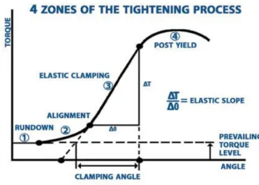
The torque-turn signature has four different zones as illustrated in Figure 3.
Figure 3. Four Zones of the Tightening Process, source: PCB Load & Torque
The first zone is called rundown and refers to the time passed until the fastener head or nut contacts the bearing surface. The second zone is called the alignment or snugging zone and occurs while the fastener and joint mating surface are closing together to achieve a ¨snug¨ condition. The third zone is called the elastic clamp range, where the torque-angle curve is constant. The fourth zone is called post-yield zone and begins at the end of the elastic zone. [3] Moreover, industrialized power tools have been developed and are being used to control the tightening characteristics more effectively. The capability of these tools to apply torque to the fasteners in a controlled fashion made them necessary while developing new friction testing machine for fasteners. Currently industry practices involve using air motors and DC electric nutrunners for tightening applications. The tightening process and the control factor of the tightening influence the quality of the bolted joint. For example, a joint tightened by a hand behaves differently than on tightened by using a power tool and a joint that is tightened having the angle as control factor, behaves differently from one having the torque. The most common ways to control and monitor the nutrunners are presented below:
2.1.1 Torque-controlled Tightening
Due to the cost-effective tools and easy handling, this method is widely used in most of the industrial applications. Both manual wrenches and advanced nutrunner can be used. With nutrunners the torque is usually measured and controlled through a torque transducer that is either built-in the system or attached on the head. This technique is more accurate for low to medium speed tightening scenarios using lightly lubricated bolts within the elastic region of the bolts elongation.
2.1.2 Angle-controlled tightening
This process requires first to tighten the threaded fastener with a relative low torque enough to ensure full contact between the surface and then to rotate it to a preset number of degrees. In that way a more accurate clamp force can be achieved. In addition, it achieves even higher clamp force by deforming plastically and in a more reliable way.
2.1.3 Elongation-controlled Tightening
When it is important to know the exact clamp force in a bolted joint, the elongation-controlled method is used. The bolt head is firstly pulled with a force equal to the desired clamp force and then the bolt is being slowly turned until the head of the bolt touches the bearing surface. This technique is extremely time consuming, and is used high-performance products (nuclear reactors and wind turbines).
2.2 Joint Types
Screw joints vary not only in size but also in type, which changes the characteristics of the joints. The most important factor influencing the quality of the joint is the “stiffness”. During the tightening, when all the parts are in contact and tight to each other (snug point), the hardness can be measured by measuring the torque rate. The torque rate is the tightening angle necessary to achieve the recommended torque of the screw dimension and quality in question. [1]
For the same screw diameter the torque rate can vary considerably depending on the length. In a plain metal joint, a short screw reaches the rated torque in only a fraction of a turn of the screw. This type of joint is defined as a hard joint. A joint with a long screw that has to compress soft components such as gaskets or spring washers requires a much wider angle, possibly even several turns of the screw or nut to reach the rated torque. This type of joint is described as a soft joint. [1] Obviously the joint hardness varies in respect to the material and characteristics of the parts contributing. For this research the hard joint is defined a tightening that the screw turns 0-30 degrees after reaching the snug point. When it turns more than 0-30 up to 120 degrees the joint is considered medium-soft.
2.3 Friction Influence
The friction in threaded fasteners cannot always be predicted and it varies according to the material, surface treatment in the interfaces, the lubrication and other factors. This device targets to offer precise values of the frictional characteristics in the thread and under-head regions and will assist on getting a deepen insight of the development of threaded fastener materials, surface finishes, plating, coatings and thread locking adhesives.
𝑇𝑇𝑡𝑡𝑡𝑡𝑡𝑡 = 𝑇𝑇𝑝𝑝+ 𝑇𝑇𝑡𝑡+ 𝑇𝑇𝑏𝑏 #(2. 1)
𝑇𝑇𝑡𝑡𝑡𝑡𝑡𝑡 = 𝐹𝐹 �2𝜋𝜋 +𝑝𝑝 𝜇𝜇𝑡𝑡 𝑑𝑑𝑚𝑚
2 cos �𝑎𝑎2�+ 𝑑𝑑𝑏𝑏
2 𝜇𝜇𝑏𝑏� #(2. 2)
Where, 𝑇𝑇𝑡𝑡𝑡𝑡𝑡𝑡 is the input tightening torque (total torque) and 𝑇𝑇𝑝𝑝, 𝑇𝑇𝑡𝑡 and 𝑇𝑇𝑏𝑏 are pitch, thread, and under head torque, respectively. The variables of Equation 2.2 are defined in the nomenclature. There are 4 unknowns in the equation: the total torque, the clamp force, the coefficient of bearing friction and the coefficient of friction in the treaded interfaces. By knowing the total torque, the clamp force and one of the friction components, one can calculate all the unknown. As discussed previously, the friction is unequally divided in two components, the under-head friction (bearing friction) and the thread friction.
2.3.1 Under-head Friction Torque
This is the friction developed between the screw head and the joint. It can simply be calculated by assuming an equivalent friction diameter (𝑑𝑑𝑏𝑏) and a constant friction coefficient (𝜇𝜇𝑏𝑏):
𝑇𝑇𝑏𝑏= 𝐹𝐹 𝑑𝑑2 𝜇𝜇𝑏𝑏 𝑏𝑏 #(2. 3)
Where, 𝐹𝐹 is the clamp force.
2.3.2 Thread Friction Torque
This is the friction developed in the thread interfaces.
By looking at the forces acting on the thread of the bolt during tightening, the equilibrium equations can be written assuming a constant friction coefficient during tightening.
It is worth noting that the normal force (N) is not in the x-y plane and therefore its projection (𝑁𝑁 cos (𝛼𝛼
Figure 4. Left: Normal force on the thread, right: Forces acting on one turn thread
In which
𝑡𝑡𝑎𝑎𝑡𝑡 (𝜆𝜆) =𝜋𝜋 𝑑𝑑𝑝𝑝
𝑚𝑚 #(2. 4)
The sum of the forces on horizontal and vertical direction must be equal to zero. � 𝐹𝐹ℎ = 0 → 𝐹𝐹𝑡𝑡− 𝑁𝑁 𝑠𝑠𝑠𝑠𝑡𝑡 (𝜆𝜆) 𝑐𝑐𝑐𝑐𝑠𝑠 �𝛼𝛼2� − 𝜇𝜇 𝑁𝑁 𝑐𝑐𝑐𝑐𝑠𝑠(𝜆𝜆) = 0#(2. 5) � 𝐹𝐹𝑣𝑣 = 0 → 𝐹𝐹 + 𝜇𝜇 𝑁𝑁 𝑠𝑠𝑠𝑠𝑡𝑡 (𝜆𝜆) − 𝑁𝑁 𝑐𝑐𝑐𝑐𝑠𝑠 �𝛼𝛼2� 𝑐𝑐𝑐𝑐𝑠𝑠(𝜆𝜆) = 0 #(2. 6) Which results in 𝐹𝐹𝑡𝑡 = 𝐹𝐹 𝑡𝑡𝑎𝑎𝑡𝑡(𝜆𝜆) + 𝜇𝜇𝑡𝑡 cos (𝑎𝑎2) 1 − tan(𝜆𝜆) 𝜇𝜇 cos �𝑎𝑎2� #(2. 7) Assuming 𝑡𝑡𝑎𝑎𝑡𝑡(𝜑𝜑) = 𝜇𝜇𝑡𝑡 𝑐𝑐𝑐𝑐𝑠𝑠(𝑎𝑎2)#(2. 8)
The thread torque can then be written considering an equivalent diameter for the thread friction (𝑑𝑑𝑚𝑚):
𝑇𝑇𝑡𝑡ℎ= 𝐹𝐹 𝑑𝑑𝑚𝑚 𝑡𝑡𝑎𝑎𝑡𝑡(𝜆𝜆 + 𝜑𝜑)#(2. 9)
By considering the bearing friction under the head of the bolt, the total tightening torque required will be
𝑇𝑇𝑡𝑡𝑡𝑡𝑡𝑡= 𝐹𝐹 �𝑑𝑑2 𝑡𝑡𝑎𝑎𝑡𝑡𝑚𝑚 (𝜆𝜆 + 𝜑𝜑) +𝑑𝑑2 𝜇𝜇𝑏𝑏 𝑏𝑏� #(2. 10)
The term "𝑡𝑡𝑎𝑎𝑡𝑡 (𝜆𝜆 + 𝜑𝜑)" can be replaced by "𝑡𝑡𝑎𝑎𝑡𝑡(𝜆𝜆) + 𝑡𝑡𝑎𝑎𝑡𝑡(𝜑𝜑)" with less than 1% error for an 𝑀𝑀10 × 1.5 mm metric screw, therefore, a simpler formulation is
𝑇𝑇𝑡𝑡𝑡𝑡𝑡𝑡= 𝐹𝐹 �2𝜋𝜋 +𝑝𝑝 𝜇𝜇𝑡𝑡 𝑑𝑑𝑚𝑚
2 cos �𝑎𝑎2�+ 𝑑𝑑𝑏𝑏
2 𝜇𝜇𝑏𝑏� #(2. 11)
2.4 Methods of Force and Torque Measurements
Another factor that describes the quality of the joint is the force that keeps the jointed parts together. [1] In this friction test rig, clamp-force is the control parameter while tightening. The system configuration is modified in a way that the output force signal is used as an input control parameter in the nutrunner. Using this configuration increases the reliability of the experiments and allows the user to have accurate force measurements taken from the appropriate measuring instrument.
These instruments are called load cells or force transducers. They are devices that receive a physical signal and change it into a measurable physical quantity through a known relationship. The signal is received using operating principles such as piezo-resistive, piezo-electric, strain gauge, capacitive, non-contact-displacement and magnetoelastic sensors.
In this application the force is applied gradually through the tightening procedure without any build-up of energy. The bolt is forced to elongate, and the desired compression of the joint is achieved. It is considered as a static load that goes between the nut and the bolt since there is no rotation of these parts. There is an angular micro-movement, but there is no dynamic loading or severe impact loading.
The type of devices that are applicable for measuring the clamp force of threaded fasteners and the torque are listed below. In modern sensors the force is usually measured by the strain produced in an elastic member when loaded, by balancing the input force with an electromagnetically developed equal one or by converting it to fluid pressure.
As far as the torque measurements is concerned, torque is the tendency of the turning force to twist an object about an axis. There are two kinds of torque measurements, static torque and dynamic torque. The static torque measurements can be either a rotary torque which is subjected to continuous rotation and are connected in line with the rotating part, or a reaction /static torque which involves little (less than 1 revolution) or no rotation of the object being measured. In this project, the static torque measurement systems are used and analyzed.
Figure 5. In-line torque transducer (left) and reaction torque transducer (right). Source: www.futek.com
2.4.1 Strain Gauge Load Cells
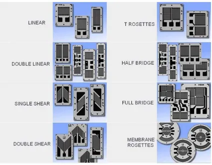
Strain gauge load cells are the most common type of force transducers. They are using bending elements and strain gauges to achieve accurate results. Strain gauges are electrical sensors whose resistance is a function of applied strain. When a force is applied in the system, the bending element bends or compresses. The strain gauge is connected to the bending element, gets excited by this displacement and converts it into a change in electrical resistance that can be measured. Usually, Wheatstone bridges are used to eliminate unknown bias with a beam assembly. [2]
Figure 6. Different types of Strain Gauges, source: digitalweigthing.blogspot.se
The cells are elastic elements where several strain gauges are bonded. The geometrical characteristics of this element determines the load capacity of the system. The total amount of force applied is measured by combining all the local strains from each strain gauge. The shape of the elements also determines the dimensional limits, the performance and the cost. The material used is usually steel or aluminum and a heat treatment is performed to achieve high level of repeatability.
Figure 7. Binocular Beam Load Cell with four Strain Gauges,source: digitalweighting.blogspot.se
Figure 8. Compression Load Cell (Right), source: digitalweighting.blogspot.se
In general, load cells range from 5N to 50 MN and can be used in high accuracy and precision applications. There are also several types depending on the working principle and the design (for example Figure 7 and Figure 8). They are working with circuits that offers the great advantage of compensating for alignment errors and crosstalk.
2.4.2 Strain Gauge Torque Cell
The most common torque sensor measurement principle uses strain gauge technology. The strain gauge is bonded to a shaft at 45 deg. to gain the maximum signal output available from the measurement. The torque applied to the shaft causes it to twist and shear stresses are created. The strain gauges that can be mounted at any point along the shaft can measure accurately enough the shear stresses.
Figure 9. Strain Gauges Bonded to a Shaft, source: appmeas.co.uk
2.4.3 Piezoelectric Crystal Force Cells
These transducers were using naturally grown quartz, but now they mostly use artificial quartz. They are active and are different from other measuring techniques, since there is no power supply needed. The signal is transduced through a very small deformation. In that way, the result
is a high frequency response that does not affect the geometry of the crystalline, but they need a high impedance cable for the electrical interface. [2]
The load/torque is applied on one contact area of the transducer and it is transferred to the inbuilt crystalline materials. A charge amplifier is used to capture the signal of the electric charges that are formed on the crystal surface of them, which are proportional to the applied load. When it comes to measuring threaded fasteners application, the sensors are preloaded. They are appropriate for dynamic applications, such as shock waves and punch press forces. On the other hand, they cannot be very effective on static measurements and low loads, as there is a small leakage that is disturbing the signal in the charge amplifier. [6]
Figure 10. Mounting of a load washer, source: npl.co.uk
They have big load measurement range and they are resistant to high overload and high temperatures. They are easy to use and usually they have many applications in laboratories and industrial applications.
2.4.4 Piezoelectric Crystal Torque Cells
The piezoelectric torque sensor works with the same principles as the piezoelectric force sensors. They are shear sensitive quartz’s that in a special arrangement can measure the torque on the system. The elements are aligned with their sensitive axis tangent to the circle where the torque is applied. They are enabled by friction, so they must be preloaded. The preloading values vary, and they are given in the specification sheets for each type. The electrical connection of the quartz element is in parallel so that the total sum is proportional to the applied torque. [7]
2.4.5 Hydraulic Load Cell
This device measures the pressure of a liquid through a pressure transducer or a pressure gauge dial, when a force is applied on it. The liquid is usually oil and has a preload pressure. This device can usually measure between 500N to 200kN, there is no need of external power and can be used as tension or compression devices. The uncertainties are around 0.25 % with very precise design, but there is a high dependency on the temperature, which is defined as 0.02 to 0.1 % per °C.
Figure 11. Example of Hydraulic Load Cell, source: npl.co.uk
One of the disadvantages is that it needs an external supply system, which makes it hard to transfer. Hydraulic load cells have a wide measurement range, but when it comes to stability, the device should be over-dimensioned and there is no exact documentation on the accuracy when vibration and shock loads are appearing. [2]
2.4.6 Pneumatic Load Cell
The pneumatic load cell works with similar working principles as the hydraulic load cell. The force that is applied on the device is transferred to a flexible material, like a diaphragm and is balanced by a pneumatic pressure on the other side. There, a pneumatic pressure dial gauge is attached, and it reads the pressure. Similarly, to the hydraulic sensors, the stability of the system in vibration and shock loads is questionable. [2]
Figure 12. Example of Pneumatic Load Cell, source: instrumentationtoday.com
2.4.7 Magnetoelastic Force Sensor
This device is based on the magnetoelastic effect, which describes the change of the natural magnetic flux density of ferromagnetic materials when a mechanical stress is applied on them. The magnetoelastic sensor can measure the torque, force, the angle and the speed of a rotating shaft. For the load measurement this sensor can measure the force when stress is applied on a linear manner (compression and tension). It is a completely contactless and extremely compact design sensor that can make continuous and dynamic measurements on both rotating and static shafts. Since they do not have any contact with the moving parts, these sensors can measure the force without influencing the input torque or force through external friction. [2]
The sensor has no need of re-calibration over time and can measure from 5 to 85kN with high accuracy and repeatability (0.5%). In high loads, vibrations and shock loading the stability of these sensors is questionable.
2.5 Combined Load & Torque Sensors
Apart from the load cells and torque cell, there have been other sensors developed that can measure both load and torque at the same time. This reduces the size of the measuring device and simplifies the configuration. On the other hand, there are no sensors developed yet that can eliminate the crosstalk. The load sensors are usually less influenced in crosstalk than the torque sensors. Some values are calculated for estimating the crosstalk of each combined system, but their accuracy is questionable.
Figure 13. Force/Torque Sensors where the sensor system is positioned in a way that the force and the torque can be measured simultaneously. Source: ATI-Industrial Automation
In applications where the accuracy of the measurement is not important, these sensors can be used. In application where the exact value of the load or torque applied is needed, the use of combined sensors is prohibited, and separate sensors are preferred.
2.6 Crosstalk
In this application, crosstalk occurs between the force and the torque created in the joint. During the tightening, friction is developed under the head of the bolt and in the threaded interfaces of the nut (Introduction). The friction can be measured by the equilibrium of torque on each interface.
Figure 14. Crosstalk in tightening. A torque is applied on the nut and the tension in the bolt develops
In the particular application, crosstalk is the phenomenon where more than one force or torque component is transmitted on one sensor, causing undesired effects and variation on the results. To have accurate measurements, crosstalk should be eliminated and use of bearings is required. The torque and force can be separated using a thrust bearing and they can be measured
individually. For locating the sensors and the other parts of the device, radial bearings and bushings are used.
In practice the significance of crosstalk is overlooked or just ignored although it may have a considerable influence on the accuracy of the measuring result. [7] For example in combined force/torque cells the crosstalk is ignored, and an uncertain error is occurred on the sensor. There are few or any guides that calculate the crosstalk occurring in tightening processes.
2.7 Bearing Selection
Bearings are machine elements that allow motion on the desired direction and reduce the friction between the parts in contact. They are divided according to the type of operation, the motions allowed, and the direction of loads applied to the moving parts. The most common types are plain bearings, rolling-element bearings (ball, roller, and needle bearings), fluid bearings and magnetic bearings. Regarding the motion, they are separated to axial, linear, and spherical motion and they can bear radial, axial and bending moments loading. Some of the factors influencing the coefficient of friction are the lubrication, materials, loads, surfaces and coatings. In this application, bearings are used to locate the sensors and the moving parts. Prior to the bearing selection, a map of the available rolling bearings is presented and some basic characteristics of them is discussed below.
2.7.1 Radial Bearings
When forces perpendicular to the direction of the shaft or radial forces are present, radial bearings are used. They can withstand axial loads, by having an axial angular contact. [8] There are many types of radial bearings that differ in the rolling elements and loading configurations. The most important are presented below.
2.7.1.1 Ball/Roller Bearings
Ball and roller bearings are the most widely used bearings in industrial and not only applications. They usually consist of two raceways and several balls or rollers in the middle. They are simple in design, non-separable, suitable for high speeds and robust in operation. They have many designs, variants, materials and sizes making them easy to use and to adjust in product designs.
Figure 16. Radial ball bearings. The first bearing is a ball bearing with a cage and a sealing, the second is a roller bearing with a cage, the third is a self-aligning ball bearing and the forth is a needle bearing. Source:
skf.com
They are used to prevent or minimize rubbing and they have rolling coefficient of friction from 0.005 to 0.025, depending on the contact area of the rolling elements.
2.7.1.2 Air Bearings
Air bearings are zero-friction bearings because the sliding surfaces are not in contact. As for their size, the supporting system takes more space than the bearing itself. A constant air supply is needed and the amount of it depends on the application and the load capacity. The stiffness of the system depends on the air supply. To maintain the system, the air filter should be monitored, and the air supply system inspect periodically. [10] The accuracy of air bearings depends highly on the accuracy of their components and they are used in high speed application with continuous rotation. When it comes to high stiffness and stability, air bearings are one step behind than bearings with contact elements.
2.7.1.3 Magnetic Bearings
Magnetic bearings have zero friction because the surfaces are not in contact. The stiffness depends on the control system, the frequency and the bandwidth. Usually the normal magnetic bearing used for small industrial application have low stiffness. They are usually 3-10 times bigger than the rolling element bearings and heavier. They do not require maintenance and they are appropriate for continuous running and high-speed applications. On the other hand, they suffer from shock loads and instability when it comes to high loading. The input can be adjusted, but in high load applications magnetics bearings should be over-constrained. Similarly to the air bearings, stiffness and stability are not their strong advantage.
Figure 18. On the left picture the magnetic working principle is presented and, on the right, an actual magnetic bearing, source: www.comcol.com (left) & www.kracht.nl
2.7.1.4 Guide Strips
Guide strips and guide rings are commonly used as the guiding solution in hydraulic cylinders where concentric linear movement of the cylinder inside the piston as well as providing a support for radial loads are required. In this application, the guide strips are used to radially locate the force cell sub-assembly inside the housing while allowing for micro movements.
Guide strips and guide rings are made of polymer materials for preventing the metal to metal contact between the moving parts. This can prevent the adhesion and hence further increase the service life of the device. The most common materials are PTFE, glass fibre reinforced polyamide, and fabric reinforced phenolic resin. The PTFE is typically used when the surface pressure is low and low resistance to chemicals, heat or wear is demanded. (Hydraulic Seals, SKF)
Guide strips unlike the guide rings can be cut into any length depending on the system dimensions. A basic cut forms an 30° angle which is used for applications with reciprocating movement. Other cut configurations are straight cut, i.e. used with rotating movements and stepped cut, i.e. used when sealing function is required.
Figure 19 Guide strips cut configuration. 𝟑𝟑𝟑𝟑° Cut (left), straight cut (middle), and stepped cut (right), source:
www.skf.com
Metal guide strips are also available but compared to them, polymer guides offer longer service life, self-lubricating and smoother movement. They have very good friction coefficient and increase rigidity of assembly.
2.7.2 Thrust Bearings
Thrust bearings are designed to accommodate axial loads and must not be subjected to radial loads and are inadequate to handle moment loads. Special thrust bearings can accommodate moderate radial loading as well, but it is not recommended. Thrust rolling element bearings consist of the two raceways, the thrust rolling elements and the cage that keeps the elements together. [8] There are thrust bearing without rolling elements, such as hydrodynamic, hydrostatic and magnetic thrust bearings. Following, a short presentation of the existing technologies can be found.
2.7.2.1 Thrust Rolling Element Bearings
They are the simplest version of thrust bearing. These bearings cannot transmit any radial load. There are different kind of rolling elements, such as ball, roller, tapered roller spherical roller and needle. Each type has distinctive characteristics:
Ball thrust bearings: They can be manufactured as single direction or double direction bearings. They are can accommodate axial loads only and must not be subjected to any radial load. [8] Roller thrust bearings: The rollers are arranged perpendicular to bearing axis and in circular fashion and can accommodate heavy axial loads and shock loads. They are very stiff, and the rollers need end-relief to reduce stress concentration in the roller and outer wall of the house washer raceway. [8]
Tapered roller thrust bearings: They are similar to roller but with an angle between the bearing axis and the line of contact. This angle determines the degree of thrust. If the angle is greater than 45 degrees, the bearing is most suitable for axial loads and once the angle reaches 90 degree, the bearing can only sustain axial loads. They need a cage and sometimes a flange. By altering the shape of the raceway, this type of bearing resists mild or moderate angular misalignment.
Spherical roller thrust bearings: The rolling elements are barrel-shaped, and the raceways look like cone-and-cup design found in standard tapered roller bearings. This provides the bearing with self-aligning capabilities. They are self-aligning, support heavy axial thrust, tolerate moderate radial loads and can accommodate misalignment of the shaft relative to the housing. [8]
Needle thrust bearings: Needle bearings are known for their small height and high number of rolling elements. They are without a housing washer and can directly be in contact with the rotating part. They can support high axial load and shock loads but not radial loads. The end of the rollers is relieved slight to avoid stress concentration. They provide high stiffness within a minimum axial space. [8]
Figure 20. Different kinds of thrust rolling element bearing. The first bearing is a double row ball thrust bearing, the second a roller thrust bearings, the third a tapered roller thrust bearing, the forth a spherical roller thrust bearing and the fifth a needle thrust bearing, source: www.skf.com
Following, a table comparing several types of bearings is presented. The table is taken by Timken and refers to rolling element bearings.
Table 1. Comparison of Rolling Element Bearings, source: Timken Feature Roller Thrust Bearing Ball Thrust Bearing Tapered Roller
Thrust Bearing Roller Thrust Spherical Bearing
Needle Roller Thrust
Bearing
Pure Axial Load Good Excellent Excellent Excellent Excellent
Combined Load Unsuitable Poor Fair Fair Unsuitable
Moment Load Unsuitable Poor Poor Unsuitable Unsuitable
High stiffness Excellent Excellent Good Good Excellent
Low friction Poor Excellent Fair Fair Good
Misalignment Unsuitable Poor Poor Excellent Poor
Locating Position
(fixed) Fair Excellent Good Good Excellent
Speed Poor Excellent Good Fair Poor
2.7.2.2 Hydrodynamic & Hydrostatic Thrust Bearing
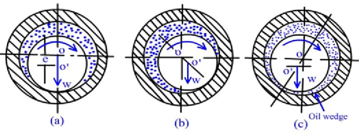
Hydrodynamic bearings use a robust lubricant or air cushion under high pressure supports the axial load. During rotation, the fluid is drawn to the bearing pad and creates a minimal-friction fluid buffer. Hydrodynamic bearings are manufactured with a tilting pad, which permits uneven thrust loads across the bearing, but maintains the fluid seal despite this misalignment and the load is supported on wedges of fluid created by the pad's geometry. Hydrodynamic bearings can suffer from high torque, high minimum loads, and excessive bearing inertia, but this depends on the type of fluid used. [11]
Figure 21. Hydrodynamic bearing. At first the bearing rests and the two surfaces are in contact (a), then the shaft starts to move, and the lubricant is concentrated on one side (b) and when the bearing is on full-speed the lubricant separates the two surfaces and a thin film is generated that allows the rotation (c), source: nptel.ac.in
In hydrostatic bearings the lubricant is pumped through the bearing assembly to maintain positive pressure. This overcomes some of the inertia and torque problems experienced by hydrodynamic bearings, but this assembly requires a continuously operating pump which should be factored into the bearing's energy efficiency. Hydrostatic bearings which utilize an air cushion have tolerances as low as 0.2 μm, making them the ideal choice for precision machining. [11]
Figure 22. In hydrostatic bearings the lubricant is constantly pumped though the bearing to maintain a distance between the bearing and the shaft, source: nptel.ac.in
2.7.2.3 Magnetic Thrust Bearing
These types of thrust bearings support loads by magnetic levitation. Permanent magnets are suitable for light loads, but electromagnets are required for moderate to heavy loads which are referred to as "active". Magnetic bearings are extremely low friction devices which do not need lubrication. With some exceptions, they are also maintenance-free. This type of bearing does not support misaligned loads. [11]
2.7.3 Bearing Materials
The most widely used material in bearings is steel. Steel rolling elements and steel raceways are used in most of the applications, because it is easier to be manufactured and their production is less expensive. When it comes to ball bearing there is the option to use ceramic materials as well. The most common ceramic materials used are ceramic silicon nitride, zirconia oxide, silicon carbide and alumina oxide (Table 2).
Table 2: Thrust bearing material characteristics
This material can be used mostly in ball bearing due to the simple geometry. Compared to the steel ball bearing, the ceramic balls are lighter and stronger and can operate smoother. The higher value of the modulus of elasticity decreases the contact area in the raceways to significantly reduce rolling and sliding friction. [8] Additionally, the lower density reduces the centrifugal forces, which may reduce friction at high speeds. [11] Ceramic materials also offer high hardness, low coefficient of thermal expansion, high electrical resistivity, low dielectric constant and no response to magnetic fields. The heat and friction are reduced, and they also have less vibrations and spindle deflection. All these advantages lead to longer bearing service life when the same operating conditions with steel bearings are assumed. [11]
In general, there are three options available for high quality and strength ball bearings. The first option is to use steel balls and raceways, the second to use ceramic balls with steel raceways (hybrid ball bearings) and the third to use ceramic balls with ceramic raceways.
Figure 23. On the left a ball bearing with steel balls and steel raceways, in the middle a ball bearing with ceramic balls and steel raceways (hybrid) and on the right a ball bearing with ceramic balls and ceramic raceways
2.7.4 Bearing Friction
Between the moving parts of the bearings, friction is developed due to deformation of the rolling elements and raceways and their sliding friction. The approximate rolling bearing coefficient of friction for each bearing type is presented in Table 3.
Table 3: Coefficient of friction for running bearing, source www.amroll.com
Bearing Type Running Bearing Coefficient of Friction
Single Row Ball Bearing 0.0015
Self-Aligning Ball Bearing (radial load) 0.0010
Cylindrical Roller Bearing 0.0010
Spherical Roller Bearing (radial load) 0.0018
Taper Roller Bearing 0.0018
Needle Roller Bearing 0.0030
Axial Needle Roller Bearing 0.0035
Ball Thrust Bearing 0.0015
Cyl. Roller Thrust Bearing 0.0050
Tapered Roller Thrust Bearing 0.0050
2.7.5 SKF model of bearing friction:
In this model, the total frictional moment consists of the following components: 𝑀𝑀𝑠𝑠𝑡𝑡𝑠𝑠𝑠𝑠𝑡𝑡 = 𝑀𝑀𝑠𝑠𝑠𝑠+ 𝑀𝑀𝑠𝑠𝑠𝑠+ 𝑀𝑀𝑠𝑠𝑠𝑠𝑠𝑠𝑠𝑠+ 𝑀𝑀𝑑𝑑𝑠𝑠𝑠𝑠𝑑𝑑#(2. 12)
Table 4: Bearing Frictional Moment Components Friction moment Description
𝑀𝑀𝑠𝑠𝑠𝑠 The rolling friction moment includes effects of lubricant starvation and
inlet shear heating
𝑀𝑀𝑠𝑠𝑠𝑠 The sliding friction moment includes the effect of quality of lubrication
conditions
𝑀𝑀𝑠𝑠𝑠𝑠𝑠𝑠𝑠𝑠 The frictional moment from integral seals
𝑀𝑀𝑑𝑑𝑠𝑠𝑠𝑠𝑑𝑑 The frictional moment from drag losses, churning, splashing, etc. in an
oil bath
A detailed calculation of the equation (2.12) is provided in “SKF Model for Calculation of Bearing Friction ”. [17]
The starting (breakaway) torque can be defined as the frictional moment that must be overcome by bearing to start rotating at an ambient temperature of 20 to 30C. This torque is equal to the maximum static torque in the bearing at that specific condition.
𝑀𝑀𝑠𝑠𝑡𝑡𝑠𝑠𝑠𝑠𝑡𝑡 = 𝑀𝑀𝑠𝑠𝑠𝑠+ 𝑀𝑀𝑠𝑠𝑠𝑠𝑠𝑠𝑠𝑠#(2. 13)
Table 5: Bearing Starting Moment Components
Friction moment Description
𝑀𝑀𝑠𝑠𝑠𝑠 Sliding friction moment
𝑀𝑀𝑠𝑠𝑠𝑠𝑠𝑠𝑠𝑠 Friction moment due to seals
2.8 Tolerances
When designing machines components, special consideration is required for defining the tolerances. If the tolerances are not calculated, a possible failure may occur and especially in assemblies. To avoid undesired effects a tolerance analysis must be done in every design to
predict the potential accumulated variation in individual components and assemblies. In that way, the tolerance stack-up can be controlled.
Tolerance stack-ups provide engineers with the ability to study dimensional relationships within an assembly, calculate part tolerances, compare design proposals and produce complete drawings. There are different ways of calculating the effects of accumulated variation that is allowed by the specified dimensions and tolerances using arithmetic or statistical calculations. The two most commonly used are the worst-case analysis and the statistical analysis and for this model the worst-case model will be used to accurately calculate the axial and radial tolerance chains and eliminate the tolerance stack up effect.
2.9 Existing Technology
There are many companies that have developed their own test rigs for measuring the friction in threaded fasteners. The most commonly used test rigs that calculate friction coefficients and monitor the tightening of threaded fasteners are listed below.
2.9.1 TesT Friction Testing Machine
This machine tests fasteners of M3 to M80, uses drives up to 60 kNm, measures clamp forces up to 6 MN and tightens with speed of 600 rpm. The measuring is based on a combined torque/cell sensor which is using strain gauges and can determine the partial momenta at the under-head and in the threads. To eliminate crosstalk, mechanical decoupling is used according to the company. There are also different additional models of this machine that share similar characteristics and can be found in the company’s website (TesT GMBH).
Figure 24. TesT friction test rig 215 series, for force/torque measurements, source: www.test-gmbh.com
2.9.2 PCB Piezotronics Testing Machine
The threaded fastener is mounted on the testing machine to determine the torque, angle of rotation and the clamp load. It includes a rotary torque angle transducer and a clamp force cell for measuring these characteristics. The clamp force cell measures not only the clamp force, but the thread torque as well. It uses a full bridge strain gauge design, but the decoupling of the sensor is uncertain. The testing software separates the thread torque from the input torque to determine the under-head friction torque and thread friction torque without taking into consideration the crosstalk of the sensors. [www.pcb.com]
Figure 25. PCB Piezotronic – System for fastener testing, source: www.pcb.com
2.9.3 BLM Testing Machine
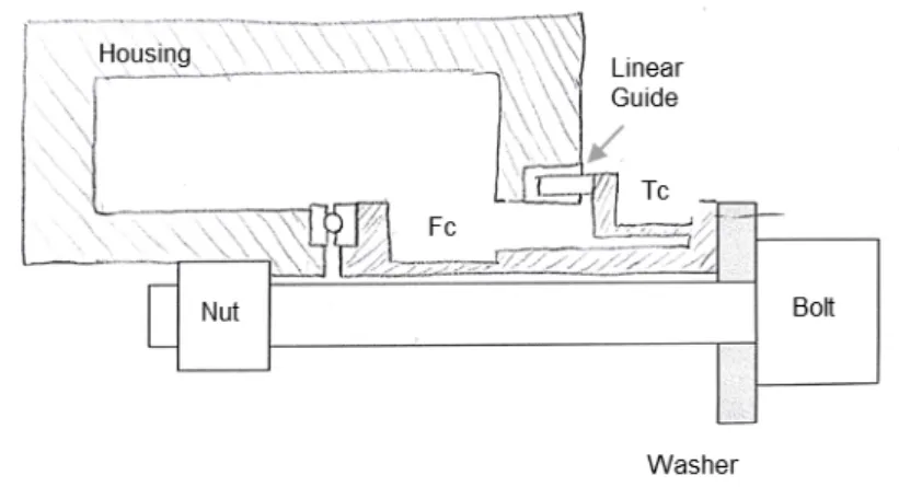
BLM Testing Machine is currently used by Atlas Copco´s researchers to determine the clamp force and thread torque on bolt tightening. The main difference from PCB´s and TesT´s testing machines is on the sensor. A force cell with strain gauges is used to measure the clamp force and a torque cell with strain gauges for the thread and total torque. These cells are decoupled with a thrust bearing that allows the micro rotation of the nut while tightening. An inline transducer is used additionally to measure the total torque applied and the nutrunner that controls the torque is mounted on the right side of the test rig on a stable mounting plate. (Figure 26)
Figure 26. BLM test rig with an inline torque transducer and the nutrunner attached.
The bolts are inserted from the right-hand side of the test rig on a washer that is tightened on the force cell. The nut is inserted from the left-hand side. Depending on the clamp length, some spacers are used between the nut unit and the fastener to replicate the clamping length. The torque in the threads (shank torque) is transmitted through the nut-carrier and the nut adaptor to the torque cell. The measurement of the shank torque is taken and the total torque can happen in the torque cell. However, the researchers are using an inline transducer (IRTT) instead of the torque cell sensor for the total torque measurement. The clamp force works between the nut and the under-head of the bolt. There are several parts involved in the clamp length, but the measurement is taken by the force cell. The output of this device is the total torque, the torque in the threaded interfaces and the clamp force. This device is used as inspiration for the developed test rig of this project.
The data acquisition system calculates the bearing torque (under-head torque). This configuration eliminates the crosstalk on the sensors but introduces a friction in the system due to the angular micro-movement of the torque cell. BLM machine can test fasteners of M3 to
M14, uses industrial nutrunners for tightening, measures thread torques up to 100 Nm and clamp forces up to 100 kN and can tighten with speed of 2000 rpm.
•
3 CONCEPT DEVELOPMENT
The knowledge acquired from the research presented in the previous chapter will assist on developing the testing machine. More specifically in this chapter one can find the final requirements, the conceptual design process and the detailed design process for three devices, the nut-adaptor, the main device and the stiffness variation device.The final device is separated in three subsystems to simplify the concept generation procedure. The concept development describes three individual subsystems, the nut-adaptor, the testing machine and the stiffness variation device.
The nut-adaptor accommodates the nuts, adjusts the clamp length and transfer the torque and force to the testing machine. The testing machine is the assembly of the components that consist the measuring system. Bearings, sensors, manufactured parts, connectors and cables are some of that subsystems’ components. The stiffness variation device is a device that helps the user to change the stiffness of the joint when required.
3.1 Nut-adaptor
The nut-adaptor is a cylindrical tube with hexagonal-shaped hole on the center that is attached on the main device and carries the nut-carrier and the nut. As mentioned in the requirements, this device will test fasteners of different sizes and lengths. To achieve that, the nut-adaptor allows the use of several bolts and nuts. The clamp length range for this application is 20 mm to 160 mm (Delimitations & Requirements). In addition, the force and thread torque produced during the tightening are transferred through this unit.
The nut is inserted to an attachment called the nut-carrier (Figure 27). For every nut there is a different attachment, but they all have the same external dimensions to fit in the shaft. The nut sizes are M3 – M14 (Delimitations & Requirements). The interfaces between nut/nut-carrier and nut-carrier/nut-adaptor are hexagonal to eliminate the relative rotation of the parts and to transfer the torque generated in the threads interface.
Figure 27. Nut-carrier. The nut is attached to this carrier and then the assembly is inserted inside the nut-adaptor.
All the generated concepts below are using the nut-carrier to attach the nut. Additionally, there is a long stick that holds the nut in place when mounting.
3.1.1 Conceptual Design
The following concepts are developed for the nut-adaptor design.
3.1.1.1 Concept 1 – Current Design
Figure 28. Nut-adaptor unit, BLM test rig concept
The first concept for the nut-adaptor uses a hexagonal extrusion to attach on the main device. The concentricity is ensured with a tight fit interface between the tube and the main device and the angular movement is retained by the hex geometry interface. To adjust the fasteners length, spacers are used in line. They can be stacked up inside the tube to reach the desired clamp length. The spacers have different lengths to achieve all possible combinations. This concept is currently being used on the BLM test rig.
3.1.1.2 Concept 2 – Bayonet Mechanism
Figure 29. Nut-adaptor unit, bayonet mechanism (left) & cross-section with nut attachment and nut (right)
The second concept uses the bayonet mechanism shown in Figure 29. This concept consists of the main shaft and the ring that are part of the bayonet mechanism. No spacers are needed to change the length. The nut has the same attachments with the previous concept. Grooved slots are used to locate the outer hex-shaped part. There are several bayonet grooves that can cover several possible bolt lengths. For example, if a bolt of 30mm is used, the ring will placed on the first groove (looking from the left). If a 200mm bolt is used the ring will be places in the last groove. Due to preset positions, not all clamp lengths can be tested. In addition, spacers can be used if a precise bolt length is needed.
3.1.1.3 Concept 3 – Shaft with Groove and Ring
Figure 30. Nut-adaptor unit with a shaft, several grooves and ring.
The last nut-adaptor concept consists of a tube and a ring. The tube has several grooves machined on the external surface as shown in Figure 30. The inner part of the ring has a square shape that allows it to be mounted on the shaft. The inner tube geometry is hexagon shaped as well and allows the installation of nuts carriers and spacers. The clamp length is adjusted by changing the position of the ring. Similarly, to the second concept, spacers are available for this option, if the desired length is not a pre-set value.
3.1.2 Concept Evaluation
Three concepts are evaluated with respect to the users´ requirements and manufacturability.
Figure 31. Conceptual design of the nut-adaptor unit. On the left side, the 1st concept is currently used on the BLM test rig, on the middle, the second concept using bayonet mechanism and on the right side, the third concept using grooves and locating ring.
The first concept is used on the current testing machine. During tightening and untightening, torques are generated in both directions. This concepts successfully transfers the torque to the measuring sensors. The range of the clamp lengths can be achieved by using the right combinations of spacers. The disadvantage of this concept is that it takes time to set-up the configuration and to change the clamp lengths for each experiment.
On the second concept the set-up time is the same with the first one. During untightening though there is a chance of failure. The ring can slip out of the groove due to opposite direction movement. If that happens the contact will be influenced, and the high torque and shock load will make the device unstable and cause measurement inaccuracies or even mechanical fails. The third concept is similar with the second concept. The advantage is that it can work in both directions of the tightening without a problem. The clamp length is not robust, but spacers can be used if needed to achieve desired length.
To continue with, for the selection process the Pugh´s Matrix is used to evaluate the pre-mentioned concepts.
Table 6: Pugh’s Matrix for the concept evaluation of nut-adaptors
The first concept is used as reference. The criteria of the evaluation are the accuracy, the ability to transfer the torque on the sensors, the robustness of the design, the feasibility, the stability, the set-up time during the experiments, the complexity and the cost. I one concept has better performance in one criteria then a ´+´ is used and if it has worst a ´-´. For equal performance there is no grading.
After the evaluation the first concept is chosen to proceed to the next phase of detailed design. It is a concept that already works perfectly and with the right modifications can work in this project as well.
3.1.3 Detailed Design
The nut-adaptor developed for this project accommodates the spacers and the nut-carrier. It has a hexagonal hole in the middle where the nut-carrier and the spacer are placed. This geometry allows the torque to be transmitted from the nut to the torque cell. The configuration is shown in Figure 32.
The device interface with the nut-adaptor is designed so that the current nut-adaptor can be used as well. However, to be able to test from 30 mm clamp length, the length of the nut-adaptor is modified in a new design.
Figure 32. 3D model of Nut-adaptor.
Due to the hexagonal hole in the middle, the nut-adaptor is difficult to be manufactured. The process needed is called EDM and the inner corner is not possible to be manufactured in the
Criteria Concept 1 Concept 2 Concept 3
Accuracy 0 -Torque Transfer 0 0 Robustness - -Feasibility 0 0 Stability - + Set-up time 0 0 Complexicity - -Cost 0 0 Sum of + 0 0 1 Sum of - 0 3 3 Sum of 0 0 5 4 Total YES NO NO Concept Evaluation R e f e r e n c e