Settlement Generation in Minecraft
Marcus Fridh
Fredrik Sy
Computer Science Bachelor Thesis 15 credits Autumn 2020Supervisor: Alberto Enrique Alvarez Uribe Examiner: Steve Dahlskog
Settlement Generation in Minecraft
Marcus Fridh
, Fredrik Sy
The Faculty of Technology and Society
Department of Computer Science and Media Technology Malmö University
Sweden
ABSTRACT
This paper explores graph grammar and constructive solutions for settlement generation in Minecraft. It uses graph grammar to flatten parts of the surface in order to increase the space for the buildings. Buildings are then generated with a constructive solution that follows a step-by-step model where different parts of the building are created in a certain order. Different parts include the shape of the foundation itself, the walls, the roof and the furniture. The algorithm picks which blocks to use on different parts of the house through an object called district palette. The buildings are divided up into areas called districts, where all the houses within the district follow a similar aesthetic style. The goal is to compare our solution with existing solutions from the Generative Design in Minecraft (GDMC) competition to see how it holds up against the other submissions. To evaluate, a user study was performed where each jury has to score four criteria: adaptivity, functionality, evocative narrative, and aesthetics. The results show that the solution had a strong aesthetics but fell behind in adaptivity, functionality, and evocative narrative. Most of it was due to not being able to generate different structures, and not cleaning up the trees around the buildings and the roads.
1 INTRODUCTION
In recent years, using Procedural Content Generation (PCG) [7] as a tool for creating content for games, or even for creating games themselves, has been a focus for many game-developers. With games such as Terraria, Rogue Legacy, No Man’s Sky, and Yavalath, with the first three being prime examples of games relying heavily on PCG as part of the core gameplay, and Yavalath being a board game created entirely by PCG itself. One reason as to why PCG is an attractive tool for game developers are the many benefits it comes with for both the games and the development process of them. Benefits include reducing the workload for the developers as well as improving replayability of the games by procedurally adding more or different content to change up the gameplay experience, thus benefiting both developer and consumer.
PCG has been used in various fields such as dungeon generation in Diablo, map and history generation in Dwarf Fortress, and village generation in Minecraft. Both Minecraft and Diablo are examples of commercially successful games [13, 14] where PCG was a major component in the core gameplay experience. Therefore, PCG is arguably a field within
In Minecraft, the player controls a character in a 3D environment consisting of blocks, where every block is aligned according to a 3D grid. The blocks are made of different materials such as wood, stone, water and earth, and the whole 3D environment is generated using PCG in real-time as the player explores further. Sometimes, players can discover generated structures within the environment. One set of structures that can be found are settlements. They consist of houses and other basic structures such as lampposts and wells, and they connect together with roads.
In an attempt to encourage further development of what PCG can be used for, a group of academics in the field of Computer Science bound together and created a competition called GDMC (short for Generative Design in Minecraft) in 2018. They wanted to encourage
developers to work with adaptativity and holisticness as the main focus, in order to push the area of PCG towards a greater adaptability and holisticness.
The goal of the competition was to produce an Artificial Intelligence program (AI) that can produce a functional, aesthetic and believable Settlement adapted to a given Minecraft map [3]. The settlements created by these AI’s will then be evaluated by a panel of judges based on certain criteria that mainly focuses on how the settlement is adapted to the environment it is located in. The criteria are as follows: Adaptability, Functionality, Evocative narrative, and Aesthetics.
The motivation behind this thesis is mainly to explore and present a method of creating settlements in minecraft using PCG, therefore the GDMC Settlement Generation Competition is a useful basis for creating such an artefact. For instance, it provides a defined set of criteria that could be used for evaluating the successfulness of the AI. In addition it provides a framework [15] that makes the reading and writing from and to the minecraft map easier.
Because of the limited timeframe in which this project will be worked on within, it has been decided that the secondary objective of the competition which is to be using a method that pushes for “holistic” PCG will not be the focus. Instead, the main objective of pushing towards greater adaptivity to content will be the focus [1]. Additionally, graph grammars and constructive algorithms have been chosen to be used due to the promising results it has shown in the adaptability in graph grammar (when generating the space from the mission [6]) and the flexibility in constructive generation. Finally, the question that this paper intends to answer is:
● RQ: How would settlements created with graph grammar and constructive solutions hold up in a settlement generation competition, using the GDMC-competition’s evaluation criteria?
In order to evaluate the success of the AI, a user study will be performed on a number of persons with great familiarity with the game, where users will be made to explore a small number of different maps that contains settlements created by other submissions’, as well as one that will be created by this artefact in a limited amount of time. The users will not be told beforehand which AI created the settlements. They will then be given a questionnaire where they will be asked to give the settlement a score according to the criteria. In addition, the
questionnaire will contain clear definitions of the different criteria taken from the GDMC Settlement Generator Competition’s own definitions.
2 RELATED WORK
2.1 Environment Adaptation
Developers have had varying degrees of success in generating content that are adaptable to an environment or in relation to a story. One example of a game that uses PCG to create content adapted to the environment is Dwarf Fortress [8]. The process begins with building the world from scratch with the help of an elevation map. It proceeds with creating several map layers including temperature, rainfall, drainage, vegetation and salinity. Biomes (plant and climate types) are then classified in each tract of the land. The next phase is the simulation of the rivers and the creation of plant and animal population, followed by world-specific fantasy creatures. It ends with a simulation of historical events (growth of settlements, forming of trade routes and waging wars) which at some point in time stops. The end results can describe the world's history and the evolution of civilization. The downside of it is the time taken by the simulation which is proportional to the size of the world.
In [6], Dormans and Bakkes propose a strategy to generate levels for action-adventure games. The idea is to generate missions and spaces separately. Missions are generated from graph grammars. By adding different rules, different missions can be generated. The results of it have a start, a goal and a number of tasks in between. The last step is to generate the spaces. In space generation, the mission structure is transformed into spatial construction and uses the shape grammars to give the spatial construction a more detailed look. The generated level shows how the spaces have been created to accommodate the missions. But it also has its downfall where a space can not contain more than one task.
2.2 Road Generation
Another well known algorithm is CityEngine [5], proposed by Parish and Müller. CityEngine is capable of generating cities similar to a city street map. It can be summarized into four different steps: roadmap creation, division into lots, building generation and geometry. Roadmap creation is based on an extended L-system containing global goalsand local constraints. It is used for creating highways and streets from an image data as input. After creation, it continues to divide the populated area of the city into smaller areas. Finally, the buildings are generated into a string from a parametric, stochastic L-system and transformed into a geometry. The results of it have a similar feel to a modern city but are not suited for creating a dispersed settlement.
2.3 MCEdit
MCEdit [10] is the framework that is used in the GDMC competition and in this research. It is an open-source map editor for Minecraft and has a plethora of features, such as:
● Navigating the 3D world using WASD controls and mouse aiming.
● Creating new worlds or open existing worlds.
● Add chunks to the world. A chunk is a 16x16 segment of the world with 256 height. ● Brush tool to add, replace or modify blocks.
● Filter tool which runs a script written in Python 2.7 [16] to perform edits to the world.
● Clone tool to make copies of blocks or entities.
In the filter tool, a selected area needs to be marked as an input. A script is then run that modifies the area, such as changing the terrain, replacing a material with another, or building structures such as houses or an entire settlement. Creating a filter for MCEdit is the focus of this research.
2.4 First Year of GDMC Competition
In the first year of GDMC competition [4], four entries were made. Each algorithm was evaluated on three different maps. The evaluation was carried out by judges with different backgrounds and expertise. The judges walked through the maps from a player perspective and answered a list of questions to illustrate the four criteria: adaptability, functionality, evocative narrative and aesthetics. The results from the GDMC competition is shown below with an overall score and a description of their algorithm:
1. Entry 1, Filip Skwarski - 4.38 points
Entry 1 begins with generating a heightmap. It proceeds by adding or expanding new structures in a random position of the map. During the process it undergoes an evaluation of elevation, layout and distance. Two types of houses can be generated, plazas or farms which are decided on the surrounding structures. The next step uses the A* algorithm to create roads that connect the surrounding structures that are passable. The result is clusters of houses connected to roads with fountains or farms.
2. Entry 4, Rafael Fritsch - 3.08 points
Entry 4 uses a process that starts with analyzing the level, which includes the block types, climate conditions, surface water, fertile ground and ground level. It proceeds with repeatedly subdividing the map into rectangular plots including laying down the roads in the middle of the subdivision. Next, it decides the structure type to build on each of the plots based on the fitness of different builders. The results of it give a similar feel to a city.
3. Entry 2, Adrian Brightmoore - 2.55 points
Entry 2 uses a more simple approach. It generates a heightmap and compares the height with the neighbors to determine if an edge has been found. The information is then used for finding a plot of land where buildings are generated with an external building generator. But due to the fact that the generator has not been adapted for the
competition, the building looks a bit larger and no roads or pathways are created between the buildings.
4. Entry 3, Changxin and Shaofang - 2.20 points
Entry 3 uses a solution that was inspired from CGA shape [9]. It begins with recursively dividing the whole area to find the surface. Once found it continues with partitioning the space into plots. The plots are used for creating the house or field by using the add and cut method. Finally the roads are created using the A* algorithm. The adaptability was low due to the flattening to the ground and the local materials were not used.
3 RESEARCH METHODOLOGY
Figure 1: Design science research methodology process.
This research will be conducted with Design Science Research Methodology (DSRM) [11] developed by Peffers et. al. It is widely used in research for identifying a problem and evaluating an artefact that is intended to solve the problem. Design science is an iterative process that provides feedback on how effectively the artefact solves the problem and which issues were found in the artefact. It is very suitable for this research in order to improve the quality of the research process and the artefact. The process of design science has six steps and is explained below:
1. Problem identification and motivation
Define the specific research problem and justify the value of a solution. 2. Define the objectives for a solution
Infer the objectives of a solution from the problem definition and knowledge of what is possible and feasible.
3. Design and development Create the artefact. 4. Demonstration
Demonstrate the use of the artefact to solve one or more instances of the problem. 5. Evaluation
Observe and measure how well the artefact supports a solution to the problem. 6. Communication
Communicate the problem and its importance, the artefact, its utility and novelty, the rigor of its design, and its effectiveness to researchers and other relevant audiences such as practicing professionals, when appropriate.
3.1 PROBLEM IDENTIFICATION AND MOTIVATION
Many PCG algorithms usually generate content from an empty state. It does not take into account any influence from the outside. This allows the developer to focus on the results of the
algorithm. But once the algorithm needs to respond to both the current and the generated content, it becomes more complicated. This requires the algorithm to adapt from the external content while generating content that fits into the current state. One such area is settlement generation where it needs to generate structures that fits into the environment. The GDMC competition provides such an environment, to explore solutions and to find out if the solution can compete with other participants. This motivated us to explore the proposed solution defined in the research question. Graph grammar was used as a way to change the surface and it is an interesting part to explore while constructive opens up for more alternatives to build the structure. It is also to find out the benefits of the adaptive solution and get a better understanding of it. This also enables other researchers to find a better solution.
3.2 DEFINE THE OBJECTIVES FOR A SOLUTION
In order to get an answer to the posed research question, objectives need to be defined.
One of the objectives is a way to read, analyze and write data from and to the given Minecraft map. First, in order to create settlements to an existing environment, reading of the environment is necessary. There needs to be a way to gather information about the environment in a useful way to then be analyzed. Secondly, after reading the data about the environment, there needs to be a way to gather meaning out of it. A way to let the algorithm know what kind of climate parts of the environment is in, to know that rivers and lakes can not be built upon, to know that mountains are too steep to attempt to build buildings on and so on. Finally, after analyzing the data, there needs to be a way to write the output of the algorithm to the map.
The main objectives that will be observed when evaluating boiled down to three things. Ensure that the algorithm analyzes the environment. Then create a settlement that in a way that is deemed adequate uses materials that makes sense. Making sense in this context means that the materials mostly could be gathered from the environment it is located in. And finally divide the individual buildings up into “districts” where the buildings follow a coherent architectural and aesthetic style. It is acknowledged that determining whether the current state of the artefact produces successful results is a subjective matter, and only by performing the later mentioned user study will the final evaluation answer the posed research question.
3.3 DESIGN AND DEVELOPMENT
In order to submit to the GDMC competition, the artefact needs to be adapted to their submission rules. This boils down to three options: The first option is to write the code in Python 2.7 and to submit the filter file along with any data files in a compressed ZIP file. Option two is to create a modification (mod) that is compatible with the Forge [17] framework. To give an explanation of the second option: A mod, in the context of Minecraft is a modification of the original game which can add or change content to create an entirely different experience, and in some cases entirely different gameplay. Forge is an Application Programming Interface (API) that allows development and loading of such mods.
Finally, for the third option, a Jar-file will be created which takes a certain MCEdit Schematics file as an input parameter. The jar-file will then perform changes over the schematic and output
a modified MCEdit Schematics file, which will then be imported to the world-file. The first option will be chosen because it seemed like the easier option to choose.
Furthermore, the artefact will need to be created from graph grammars and constructive solutions. The definitions of these methods does not allow for evaluation of the output in order for it to be re-generated. Therefore a step-by-step model of the algorithm is chosen, which is explained in chapter 5.
3.4 DEMONSTRATION
The artefact will be used together with MCEdit to generate the settlement. It will also contain input that can affect how the content is generated. In MCEdit, it is also possible to move around in the map with a free-roaming camera view to inspect the level and the content created by the artefact.
3.5 EVALUATION
During work on the artefact, in order to evaluate the design, the data that is gathered by simple observation will then be compared to the objectives mentioned in the second step. If it is deemed not adequate enough to the goals, changes will be made to get closer to what is envisioned. This will be an iterative process that goes on for the majority of the development of the artefact. Finally, when the artefact produced results that are good enough, a user study will be made where experienced Minecraft player will be opening up minecraft maps in the game itself, that contains settlements created by a number of different GDMC-submitted settlement generators, as well as one created by this artefact. They will not be told which settlement was created by which generator, and the order in which the maps are explored is randomized for each participant. The randomization will be done by giving each settlement generator including ours a unique value. Then we will use a randomizer website [2] where we will enter all the unique values and shuffle the order for each participant. Five minutes will be given to explore each settlement, and after each exploration-period they will be asked to give a score on a questionnaire for the corresponding settlement. They will give a score (1 - 10) on each of the different criteria (adaptability, functionality, narrative and aesthetics). A description for each of the different criterias will be written on the questionnaire for reference, and the definitions that will be used as a guide for the participants when setting scores on the different criterias are all taken from the ones written in the GDMC paper [3]. They are the following:
Adaptability:
● Do the structures in the settlement adapt to the terrain?
● Do the structures in the environment reflect the environment, i.e. usage of available
material, adaptation to the biome?
● Does the settlement take advantage of terrain features or compensate for problems with the terrain?
Functionality:
● Does the settlement provide protection from danger?
○ Does it keep mobs from spawning? ○ Does it keep mobs out?
○ Protection from other environmental dangers?
● Is the settlement accessible to a player avatar in survival mode?
○ Can you walk everywhere?
○ Does the settlement provide faster modes of transport? ○ How easy is it to find your way around?
● Does the settlement provide the player with additional affordances?
● Does the settlement make resources easy to obtain?
● Is there an easy way to get food?
● Does the settlement provide functionality to the villagers? ● Does the settlement reflect the embodiment of the player avatar?
● Is it appropriately scaled?
Narrative:
● Is the settlement evoking an interesting story?
● After looking at the settlement, could you give a short description of what this settlement is about that sets it apart from other settlements?
● Is it clear what the function of the settlement is?
● Does this function make sense in regards to the terrain and environment it is in? I.e. is
the logging camp in a forest, the harbour town at the sea, ... ?
● Is the functionality of the settlement supporting this narrative function? I.e. does the fortified frontier settlement 6 have functioning walls, is the farming village equipped with functioning fields?
● Does the final settlement give any indication of how the settlement developed?
● Is it possible to look at the settlement and imagine in what order things were built, or what stages the development of the settlement took?
● Is there an indication of the history of the settlement evident in the structure?
● Are there any convincing and consistent allusions to human cultures or specific points
in history that the settlement is modeled after – Does the settlement have a culture - either fictional or historical - that is evident from the settlement? – Do you know things about this culture just by looking at the settlement?
Aesthetics:
● Does the settlement look good?
● Is there a consistent look to the settlement? Does it appear that all structures belong to
the same settlement?
● Is there an appropriate level of variation in the existing structures?
The GDMC paper contains one more guideline that has been chosen to not be included in this user study due to it involving the testing of the same generator on multiple different maps. It will be decided to not test the same generator on multiple maps due to time constraints.
The tests will be done over Discord [12], where the participants share their screen to allow for observation and supervision. Finally, the results that this study gives will be used to determine an answer to the posed research question. The generators that will be used along with the artefact in the user study are: Filip Skwarski’s [18], Adrian Brightmoore’s [19], Ehaucklo’s [20], and Julos14’s [21] GDMC submissions from the last competition in 2019.
3.6 COMMUNICATION
This paper describes the solution used in the artefact. Furthermore, the evaluation of the artefact will be discussed and what advantage and disadvantage it has. Also, the artefact uses graph grammar on the surface that has not been tested in GDMC competition before. Finally, the solution of this artefact can benefit for future participants of GDMC competition or in the field of adaptive content generation.
4 DEFINITIONS
Throughout the fifth chapter where the artefact, and how the algorithm works is described, some terms are frequently used that need definitions for the reader to understand what is meant. Some of these definitions are pre-existing definitions taken from the game Minecraft, while others are terms that have been created for describing certain components of the artefact itself.
4.1 MINECRAFT WORLD
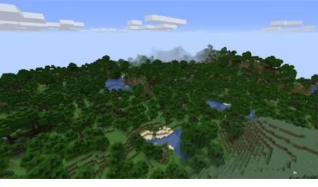
The Minecraft world or the level where the artefact will be used are split into three different dimensions: the overworld, the nether and the end. The overworld is a dimension in which the player starts their journey. It is also the focus of the GDMC competition. The overworld is a complex environment with a variety of features such as the biomes, oceans, plants, caves, daylight cycle, mobs and structures. These are important when designing an adaptive artefact. As for the other dimensions, these can accessed via portals in the overworld and contain various materials and mobs, but for the competition, it will have no significance.
Figure 2: The overworld.
4.1.1 CHUNK & ALTITUDE
A chunk is a segment of the Minecraft world and has a width of 16 blocks, length of 16 blocks and a height of 256 blocks. Chunks are a method used by Minecraft to load the chunks around the player while unloading the rest. This makes it playable and easier to manage since a map can have over 30 million chunks. But for the GDMC competition, this will not be important as the map has a size around 256x256 blocks or 256 chunks.
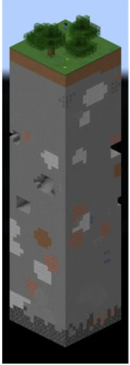
The altitude in Minecraft ranges from 0 to 255 block layers as seen in Figure 3. Highest sea level is around 62 and it is also around this height which the settlements will be generated on.
Figure 3: Altitude of Minecraft. Figure 4: A chunk. 4.1.2 BLOCKS
A block is a basic unit of a structure and has volume of one cubic meter. The world consists of different types of blocks which can be used for crafting and building. Using the block, different structures can be built such as castles, boats or mazes. For the settlement generation, the blocks can be categorized into 5 different groups: plant, pavement, building material, furniture and natural resources.
4.1.3 BIOMES
A biome is an area that can be classified with the plants and animals. Each biome has geographical features that differ from each other. Biomes in Minecraft are separated into 6 different temperature classes:
● Snowy Biomes ● Cold Biomes ● Temperature/Lush Biomes ● Dry/Warm Biomes ● Ocean Biomes ● Neutral Biomes
There exist 67 biomes in the overworld and can be distinguished by the grass and leaf colours. The biomes can be retrieved in the MCEdit and can be used for adapting the generated content.
4.2 ALGORITHM
This sub-chapter defines different terms created to refer to certain parts and concepts of the algorithm.
4.2.1 DISTRICT PALETTE
The district palette is an object containing data on which block-types will be used as material when building certain parts of the house. The district palette contains data on the following locations of the house:
● Flooring
● Foundation block ● Block at corners
● Roof block
● Block beside corners ● Block at floor level ● Block above floor level
● Block beside door
● Block above door
● Block under window ● Block above window ● Window block
● Default building block (mostly used for walls)
In addition to 4 blocks that contain the blocks making up a 2-block tall door, which are named the following:
● Bottom door block in X-axis ● Top door block in X-axis ● Bottom door block in Z-axis
● Top door block in Z-axis
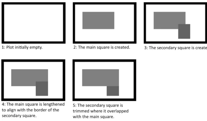
4.2.2 MAIN SQUARE AND SECONDARY SQUARE
The houses shapes seen from above are created by placing down one or two squares in a rectangle, shifting them around to fit within certain rules, and trimmed to certain shapes (see figures 13-16). They are initially used to create the shape of the foundation, but are continually referred to and used throughout the algorithm when dividing up the house into segments, building roofs and building furniture. One square is always used in all cases, and is called the main square. When two squares are used, the smaller square is called the secondary square.
4.2.3 TERRAIN-TYPE
While a biome is a Minecraft term describing different habitats and environments found in the world. A distinction is made between the biomes seen in Minecraft, and the kind of environmental types that the algorithm differentiates between. There are a large number of biomes in minecraft, and the algorithm narrows down these into five different categories which are to be referred to as terrain-types. These include Grassland, Rock, Yellow desert, Red desert and Mesa. This is necessary due to the majority of the Minecraft biomes being similar enough to each other to warrant the same style of houses being used over multiple biomes. Instead of creating a long list of biomes which would contain a certain style of houses, these five different categories were created. Which environment a house is located in is determined by observing the surface blocks, and then picking the category which the most common block belonged to. For example, stone, gravel, andesite, diorite and granite blocks all belong to the rock terrain-type.
5. ARTEFACT
The artefact is a filter for the MCEdit. The filter contains Python code that can be executed once a selection box has been created. There is no limit where the filter can modify in the map, but the artefact has been designed to only modify in the selection box, and it is also the recommendation in the GDMC competition.
The artefact can be divided into several systems in order to build the settlement. They are surface adaptation, district design creation, house generation and road generation. In the first step, the input data is sent to an adaptation system to find out all the chunks that fulfill certain criteria. Input data consist of level data and generation configuration. The matched chunks are converted into a graph. Graph grammar is then used for surface adaptation. Then house generation is used to build the buildings. Finally, roads are created with a road system, connecting all the buildings within the range. A more in-depth explanation will be explained on each part of the pipeline below.
Figure 5: The pipeline for generating the settlements.
5.1 INITIALIZATION
First, a set of initializations are made. One of which involves the initialization of a set of lists containing objects representing furniture that are later used to build pre-made pieces of furniture. For example, during the house creation process, furniture is placed around the house. Different rooms will have different sets of furniture. Rooms include bedrooms, kitchens, living rooms, storage rooms and libraries. They all have corresponding sets of furniture that the room can contain. These furnitures are randomly placed in locations around the room that have been set to allow placement of furniture. The types of furniture a certain room can contain is initialized here. Each type of furniture is represented by an object of the corresponding furniture-type class. For example: the chair class contains code that places down certain blocks at certain positions relative to the location where the chair is supposed to be created. The chair consists of a wooden slab block making up the seat, as well as three wooden trapdoors that are creatively used as chair armrests and the backrest (see figure 6).
Figure 6: screenshot from MCEdit taken of a chair made up from a wooden staircase block and 3 wooden trapdoors
Additionally, to give an example of how the furniture is stored and used with the room-type lists, the storage room furniture list contains four chest objects, one empty object and one crafting table. The more of the same object contained in the list, the greater the chance of that piece of furniture to be randomly picked when placing down that particular piece of furniture.
Furthermore, level data is extracted from the level and saved for later use. It contains information about the world, biome and material that is necessary when adapting the content.
5.2 SURFACE ADAPTATION
Surface adaptation is the process in which the height in the world surface is modified. It begins with filtering the chunks in the world that fulfills certain conditions, such as the altitude and the materials. Chunks are then used for extracting the height, the material and the edge to 2D arrays. The content of the 2D arrays is explained below:
● Height array
● Material array
Containing the surface material of each block. The value can be ground, water or lava.
● Edge array
An edge is detected if the nearby blocks with the same height have a max width or length of two. The value can be true or false, indicating if it is an edge.
Figure 7: Height in a chunk. Figure 8: Material in a chunk. Figure 9: Edge in a chunk.
Furthermore, the information from the 2D arrays are combined together so that a distinct separation can be made to the blocks. The separated blocks can in turn be represented as an undirected graph with the separated blocks as nodes, connecting the neighbors vertically or horizontally. The nodes are identified by combining the value in each array. Finally, the nodes and edges are used in graph grammars to adapt the surface. Graph grammars are further explained in the following section with a short explanation and the changes made in order for the adaptation to work.
Figure 10: Combined 2D arrays. Figure 11: Undirected graph from Figure 10.
5.2.1 GRAPH GRAMMAR
Graph grammars are described in [4] and further discussed how it can be utilized to generate non-linear missions. In summary, graph grammar can be described as a type of grammar that manipulates a graph containing nodes with edges instead of strings. In graph grammar, nodes and edges are replaced by defining a rule containing a set of interconnected nodes with edges,
and a corresponding set to be replaced with. The idea is to use the same process for merging the nodes to increase the area, similar to flattening pits or removing obstacles before building the structure.
5.2.1.1 RULES
The problem of applying graph grammar to the surface is the amount of rules that needs to be created in order to cover all the heights, which is not feasible. Instead, the height differences are used when creating the rules. The idéa is to set the current working height to a value equal to the current working node. An offset is then calculated when traversing the graph from the current node and the neighbors. When a match is found, the interconnected nodes get replaced with the corresponding nodes. A simple rule is defined in Figure 12 and matches the top-left part of Figure 10. The result is a rising ground where the edges have been merged together. The process of graph grammar is run until no more changes can be made to the graph.
Figure 12: A rule to raise the ground to the same height as the edges.
5.3 CREATING A STYLE FOR A DISTRICT
When district and plot partitioning has been completed, the step where the overall theme and design that will be applied on all of the houses within a district begins. It starts by getting the X and Z Origin coordinates, as well as the length and width that will determine the size and location of the district. Then it determines if the houses in the district will be poor, intermediate, or rich based on how many houses the district contains (see alg 1).
Algorithm 1: Determine district “wealth-score”.
houseAmount = len(center_coords)
if houseAmount >= 7: if random.randint(0, 10) >= 8: wealthScore = 0 else: houseAmount = 7 if 9 > houseAmount >= 5: if random.randint(0, 10) >= 8: wealthScore = 1 else: houseAmount = 0 if houseAmount < 5: wealthScore = 2
The Wealth-score is used to determine whether one or two “squares” will be used to build the foundation of the houses (more on this in chapter 5.5), as well as if the houses shall be one or two stories tall (see alg 2).
Algorithm 2: Determining amount of squares and stories. # two squares twoSquares = False if wealthScore == 0 or wealthScore == 1: twoSquares = True elif wealthScore == 2: if random.randint(0, 10) >= 5: twoSquares = True else: twoSquares = False # two floors twoFloors = False if wealthScore == 0: twoFloors = True elif wealthScore == 1: if random.randint(0, 10) >= 5: twoFloors = True elif wealthScore == 2: twoFloors = False
The corner coordinates, the width and height, and the variables determining the amount of squares and stories are returned as parameters of a “DistrictData” object to be used later.
The next step is to create a district palette. For the artefact, a way to store information about which blocks should go where on a house that could be applied to different houses in the same district that might have different shapes and layouts is needed. For example, a block over a window should be a certain type of block over all windows of all houses in a district. When building the houses, this district palette will be used as a reference when each block is placed (see fig 13).
Figure 13: Example of generated house seen from the side. Which blocks are placed are determined by referencing the district pallette, using the block saved on each of the above mentioned locations on the house.
● Foundation block
● Block at corners
● Roof block
● Block beside corners ● Block at floor level ● Block above floor level
● Block beside door
● Block above door ● Block under window ● Block above window
● Window block
● Default building block
In addition to 4 blocks that contain the blocks making up a 2-block tall door, which are named the following:
● Bottom door block in X-axis ● Top door block in X-axis ● Bottom door block in Z-axis
● Top door block in Z-axis
The main factors that decide what blocks will be used on the different locations are which terrain-type the district is located in, and which trees are the majority-type in a certain distance from the district. An algorithm to determine the main tree-type is run first followed by an algorithm to determine the terrain-type. The algorithm checks all coordinates within a certain distance from the district (40 blocks in each direction), and the tree it finds the most of is chosen. Similarly, the algorithm looks at all surface blocks inside the district-area, and determines which terrain-type it should be considered as based on the kind of ground-blocks found. The amount of biomes in minecraft is many, therefore the amount of terrain-types are narrowed down to five different categories for simplicity’s sake. They are the following: Grassland, Rock, Yellow desert, Red desert and Mesa. When the main tree-type and the terrain-type is determined, each district palette variable gets assigned a certain block. There are between one to three alternatives that can be picked based on each combination of terrain-type and tree-type. These are randomly picked.
The inspiration behind using the district palette solution came from observing a lack of different patterns or blocks on walls in the settlements created by Minecraft itself, but also from the GDMC submissions. The walls were mostly created by a single block repeated everywhere, which can seem lacking in terms of aesthetics. Using different kinds of blocks at different positions on the wall that follow a coherent theme over several buildings close to each other became a big motivator behind the district palette solution.
5.4 HOUSE GENERATION
This section of the chapter describes the process in which a house is built and added on a plot on the given Minecraft map. When the idea for the houses being made with constructive methods were conceived, it was decided that a step-by-step structure would be used. Then came the decisions of the steps themselves. The steps used by the finished artefact grew somewhat naturally when a certain problem was thought of, and a solution needed to be found. For example, one of the problems was how to create the shape of the house. Research was made to find suitable methods to use, while keeping simplicity in mind when deciding on solutions due to time constraints, and the fact that these problems were only partial problems of the main one, which was to build the house itself. Not the bits and pieces of it. In the end, it was decided that it made sense to create the buildings starting from the foundation, and then mainly build the pieces that would be placed on top of that previous parts, and so forth.
5.4.1 PARAMETERS AND OVERVIEW
After the plots have been created from the nodes with space partitioning, and divided into districts, and the district palette for the current district has been created and saved, the algorithm moves on to building houses. Each of the plots contained within the district gets looped through, and a house is built for each. The houses themselves are created as new objects with input-parameters containing the level, the box, a random integer value that determines which direction the entrance will point towards, the boolean value determining whether or not the house should contain one or two squares for the foundation, yet another boolean value determining whether or not the house should be one or two stories tall, an integer that contains the Y-value on the axis that should be the ground level where the foundation is built, and finally the districtPalette object that contains the necessary data describing which location on the house should contain which block.
The house-creation process is a step by step process in which methods are called one after another that handles the building of certain parts of the house, and some that handles assigning values to certain lists and arrays that are in turn used by the building methods. When one part of the house is built, it is considered final, and is not changed in later executed methods.
5.4.2 DETERMINING THE SHAPE OF THE HOUSE
At this point it has already been decided whether or not the house will be two stories tall, and contain one or two squares for the foundation. To create the shape of the foundation, seen from above the house, one or two square shapes are placed inside a rectangle reflecting the size of the plot. The locations and sizes of these squares are random although they have to be between certain minimum and maximum limits, and they can not go outside of the plot borders minus one block in each direction. These limits are modified slightly for one of the squares when it is determined that two squares shall be used to build the foundation. This is done to ensure that there is a high enough chance that a second square can fit within the plot.
One square is always created in all instances, which will be referred to as the main square. An origin location and a length and width is then chosen. If only one square is used, after its placement the algorithm moves on to the next step. Otherwise, another square is created similarly. This square will be referred to as the secondary square. The secondary square must follow a number of rules so that it is ensured that there is adequate walking space inside the house (the secondary square sticks out at least 4 blocks), and that the foundation itself has a certain shape. A house will always either be square-shaped (if only one square is used), L-shaped or T-shaped. The secondary square is smaller than the main square. It can not be overlapping the main square. The squares might need to be modified or shifted to ensure that the foundation has an L or a T-shape. Figures 14-17 gives a visual representation of what is happening at this stage. When the secondary square has been created, and if the house will have two floors, there is a 50% chance that only the main square part of the house will be two stories tall, and that the secondary square will only be one.
Figure 14: Example of how squares are used to create the shape of the house foundation. The main square is lengthened to align with the furthermost edge of the secondary square. This house will have an L-shape.
Figure 15: Example of how squares are used to create the shape of the house foundation. The main square is shifted upwards to leave enough room for the secondary square to contain adequate walking space. This house will have a T-shape.
Figure 16: Example of how squares are used to create the shape of the house foundation. In this instance, there is not enough room to shift both the secondary and the main square to leave adequate walking space inside the secondary square. The secondary square is then discarded and this house will have a square shape.
Figure 17: Example of how squares are used to create the shape of the house foundation. The secondary square is initially placed inside of the main square, and needs to be moved out. This succeeded and the house will have a T-shape.
When the foundation shape has been made, the height of the first floor is randomly chosen to be between three and five blocks from floor to ceiling. And finally it is randomly chosen if the foundation itself should be one or two blocks tall. This data is saved in variables that are used later for the building process.
5.4.3 BUILDING THE FLOOR
When the shape of the house foundation is completed, a 2D array is created that will be filled with integer values symbolizing different parts of the house seen from above. The array has the same length in the dimensions as the house plot. This array is used by the algorithm to know which locations in the map to place the different building blocks. Figure 18 demonstrates the initial process in which values are assigned to the array. Values are later altered in the algorithm when walls and doors are assigned positions.
Figure 18: Demonstration of the values added to the array. Each square represents a cell in the 2d array. The colors represent the values seen above.
When values are set, triple-nested for-loops go through each cell in the array Y amount of times where Y is the height of the foundation. cells containing values 1 and 3 are built using the foundation-blocks, reading from the district palette. Cells with value 2 are built using the floor blocks.
5.4.4 BUILDING THE ROOF
The roof is built next. It is created in segments, where the roof covering each square is built separately. If only the main square is used, the roof-building process is straightforward. A
triple-nested for-loop loops through the length and width of the main square, and through the height, which is calculated by the following formula:
Y = X / 2 + 1
Where X is the length of the longest side of the main square. Two lines of roof-blocks are built along the long side of the main square, starting one block away from the wall, and beginning and ending one block away from the short side of the wall respectively. For each level in height, the lines of blocks are built one block further in towards the center, creating an upside-down V-shape.
If there is a secondary square, another roof is created similarly. The ridge of this part of the roof is aligned perpendicular to the longest side of the main square. A gap might occur between the roof over the main and the secondary square as shown in figure 19. This is filled in by placing more blocks from the edge of the secondary square’s until it hits the main square’s roof. Then all blocks on the inside of the roof are deleted, in case there might be leaves from trees occupying the space. The material of the roof is picked from the district palette
Figure 19: Figure showing the gap that can in some instance occur between the roof-segments. Note that the walls and windows at this stage do not exist contrary to what the image is showing. Only a hovering roof and the foundation exist.
5.4.5 DIVIDING ROOMS AND BUILDING WALLS
The inside of the house is made up of different rooms that contain different types of furniture. Space partitioning [7] is the chosen method of dividing up the inside into rooms.
Firstly, the house is cleared on the inside of all blocks that might be taking up space, such as leaves from trees. Then a wall is first created where the main square and the secondary square collides. This choice is made because space partitioning is best used inside rectangle-shaped environments. Problems would arise if a wall was to be created in a way that gave too little walk-space inside the secondary square-segment. Only one side of the walls
created through space partitioning gets recursively divided further. This ensures that there is a variety of size in the rooms, and not all of them become as small as possible. Every other division would be made along the X and Z axis respectively. Rooms will only be continually divided if the length of the room in its current division-axis is longer than 9 blocks. Furthermore, divisions would only be made to ensure that the shortest edge of a room is at least 4 blocks wide (see fig. 20).
Figure 20: Example of how the rooms are divided up using space partitioning.
Next, the floorplan array gets its values updated to reflect the changes. At every cell corresponding to a block belonging to an inner wall, the value 4 is assigned. A doorway is then assigned to each wall that is more than one block wide. This is done by assigning the value 5 to a randomly chosen location on a wall’s corresponding floorplan array cell. Each room that is created gets an object assigned to it that contains the origin coordinates, length and width. These objects are used later when deciding what type of room furnishing the room will contain. The walls themselves are then built using the blocks picked from the district palette. This is done by looping through the floorplan array, and building a pillar of wall-blocks at every location that has a corresponding cell containing the value 4. For the cells containing the value 5, a doorway is created that will later be filled with a door. Finally, the cells that correspond to the locations in the room where furniture will have a chance to be created are assigned the value 6 as shown in figure 21. Furniture will not be created close to doors as to make room for walking around in the house.
Figure 21: Figure displaying where furniture can be placed. Furniture can only be created along walls, and at least 1 block away from doors in every direction.
Now that the inner walls are built, the next step is to build the outer ones. Before the building process starts, a wall needs to be chosen to have the entrance door. The direction of which the door will point towards was already given as one of the input parameters as mentioned before. The walls are looped through, and the first wall that points in the correct direction is chosen for the entry door. However before building the entrance door, the walls themselves are built. Every position that has a corresponding cell in the floorplay array with the value 1. Using the array and knowing the height of the first floor, and the buildlayer, the right blocks are placed at the right locations using the district palette.
Now the door location on the chosen wall is randomly selected, and the corresponding cell in the floorplan array is set to 5. The furniture locations are then also updated so no furniture can be created next to the entrance door. The staircase leading down from the door to the ground is then built using standard cobblestone stairs.
Then windows are created. They are randomly placed along the outer walls, except for one block next to corners, T-crosses, and doors. (see fig. 19 for examples of windows created on the first floor). And lastly, the corners have their blocks built with the corresponding district palette blocks.
5.4.6 BUILDING POSSIBLE SECOND FLOOR
If it has been chosen that a second floor shall be created, the algorithm first builds a staircase leading up to the will-be built second floor. The longest wall is chosen so that the staircase will have to turn the least amount of times before reaching up to the second floor. The staircase starts at the origin of the wall, and is built along with it using wooden stairs blocks. If the wall is not long enough to contain the staircase going straight ahead, the staircase turns, and follows
along the next wall connected to the first one, and so on. Figure 22 shows a staircase that turned along the corner of the wall twice.
Figure 22: A screenshot taken from MCEdit showing a two-story house with a staircase spiralling around the corners to reach the second floor. Parts of the ceiling of the first floor, that also acts as the floor to the second floor is also shown.
When the staircase has been built, the cells in the floorplan array that correspond to the locations of the staircase blocks are assigned the value 7, so that the algorithm later knows where to not place the second floor floor blocks, and so no furniture is placed underneath and overlapping the staircase itself.
Regardless of whether there should be one or two levels to the house, the ceiling to the first floor is created, which is used as the floor to the second floor as well. This is done once again, by referring to the floorplan array, and only placing blocks that have corresponding cells in the array that contains certain values (2, 4, 5 or 6 in this case) (see fig. 22).
Next is the building of the second floor walls, if the house should be made up of two floors. First, the outline that goes along the outer walls on the same height as the ceiling of the first floor is built (see fig. 13). The algorithm places the blocks on all positions that have corresponding cells in the floorplan array with the values 1 or 3. Then the inner walls are built, and they are always just three blocks tall from the floor to where the roof blocks start over the open room (see fig. 13). The room layout of the second floor in the main square is the same as on the bottom floor. After the inner walls are built, the outer walls are built the same way as the outer walls on the first floor were made, except no entrance door is created on the second floor and they are built on the second floor level of the house.
If the house is made up of two stories, the main square is guaranteed to be two stories tall, but the secondary square is not guaranteed, as mentioned earlier. However, if the secondary square is chosen to be two stories tall as well, The process of building the outline,
and the outer walls is the same as for the main square. Since the doorways are created when the inner walls are created, there is a doorway leading out to the secondary square regardless of the secondary square being two stories or not. If the secondary square is only one story tall, this hole is covered up. The inner walls at this point only lead up a certain height before there is empty space between the wall and the roof. This empty space is filled in as shown in figure 23.
Figure 23: The gap above the inner wall and the ceiling seen furthermost away from the view has been filled in with outline-blocks, and default blocks.
5.4.7 BUILDING THE GABLE WALLS ON THE ROOF LEVEL
At this point, most of the structure of the house is built. However, there are still gaps at the gables of the house in level with the roof that needs to be filled in with walls. Starting with the main square, which always exists, outline-blocks are placed along the height one block above where the roof blocks start at each end, then the rest of the gap is filled in with default-blocks. For each gable, if the width of the table is wide enough, a window will be built to replace part of the large space made of default blocks. In order for a window to be created, the gable must be at least 9 blocks wide. This process works the same for the secondary square. However, the secondary square only has one gable, since the other end is connected to the main square. The location height-wise can also be different from the main square, in the case that the main square is two stories tall, but the secondary square is only one, but the main principle remains the same.
5.4.8 FURNISHING THE HOUSE
Other GDMC submissions often focused on the exteriors with empty interiors and a lack of furniture. Specifically when it comes to furnishing different rooms differently from each other. For example, Ehauckdo’s [20] interiors for the skyscrapers were made the exact same on all floors, with the same furniture being placed in the same locations for all floors. To create more variety and create content inside the buildings themselves, furniture is used to break up the monotony observed on the interiors in other GDMC submissions.
The structure of the house is completed, and the only part left of the house-creation process is the furnishing. Firstly, the algorithm decides which rooms will contain different sets of furniture. This is done by putting all of the rooms on the first floor in a list, and sorting it by size. Then each room in the house is assigned a room-type. The types of rooms that can be chosen are bedroom, kitchen, livingroom, storage room, and a library. The assignment process follows certain rules to ensure that the important rooms always exist regardless of how many rooms a house contains. On the first floor, the smallest room is always the bedroom. If there is more than one room on the first floor, the second smallest room is always the kitchen. If there are more rooms on the first floor, the biggest room is always the living room. And if there are even more rooms, the rest are randomly assigned to be either storage rooms or libraries. If there are two floors, the rooms on the second floor are randomly assigned to be either storage rooms or libraries as well.
After each room has been assigned a room-type, the doors are placed in the empty doorways in the house. The floorplan array is used, and wherever a cell containing the value 5 is found, a door is placed at the corresponding location in the house, using the district palette to determine which type of door will be placed.
Next the furniture is placed down in the rooms. A list containing each of the locations in the room that can hold furniture (the positions that have a corresponding cell in the floorplan array that contains the value 6), as well as an integer representing the direction which points towards the empty floor (a position that have a corresponding cell in the floorplan array that contains the value 2). This points the furniture towards the center of the room in most cases. Then this list is shuffled, to ensure that when it gets looped through, neighbouring locations do not have their furniture placed down after each other. After the list has been shuffled, it gets looped through, and a piece of furniture is randomly chosen for the corresponding furniture list. For example, the bedroom has the furniture list containing the bedroom furniture, and only among the bedroom furniture will a random piece of furniture be chosen. However, the first item in this list is not considered when randomly choosing. This is because it is reserved to only be placed once in the room. In the bedroom furniture list, the bed object is located first. This ensures that only one bed is placed in the bedroom, and only the empty object and the bookshelf is considered when randomly choosing a piece of furniture.
Additionally to the pre-made pieces of furniture placed alongside the walls of the rooms, if the current room is a living room, a red mat will be placed down in the center of the room, covering the floor. The floorplan array is used to determine where to place the
contains the value 2). Similarly, if the room is a kitchen, the entire floor is changed out to double stone slabs. Figure 24 shows examples of different types of rooms containing their corresponding sets of furniture.
Figure 24: Image containing 4 screenshots of 4 different types of rooms with their corresponding sets of furniture. To the top-left is a kitchen, to the top-right is a living room, to the bottom-left is a storage room, and to the bottom-right is a library.
5.5 ROAD GENERATION
The road generation is generated using a simplified idéa of global goals and local constraints from CityEngine [5]. Unlike the global goals and the local constraint, this directly creates a global road that connects each district to one another. Global roads are then used as a basis for the local road to connect to.
5.5.1 GLOBAL ROAD
The global road is created by retrieving a global position from each district. Global position can be found by calculating the distance from each house to the centre of the district. The closest to the centre is chosen as the global position (see Fig. 25). This is to distribute the local road evenly around the global position. All the global position are connected with the A* algorithm to form the global road. The process of connecting the global position is done by choosing two random positions acting as a starting point and as a goal. The A* algorithm will then create a road between the starting position and the goal position. The road created with the A* algorithms are added to the goal so that the unconnected position can find a shorter distance to the global road. The process repeats until all the positions are connected to the global road. During the process of creating the road, the height difference between the current and the upcoming block is taken into account, allowing the algorithm to create a staircase where it fits.
Figure 25: Example of global position in each district and the generated global road and local road. 5.5.2 LOCAL ROAD
After the global road, the local roads are created by connecting the unconnected houses to the nearest road. It uses the same process from the global road where a randomized position is chosen. Proceeding with using A* algorithm to find the shortest distance from the house to the road. The process is finished when all houses are connected with each other.
5.5.3 ROAD MATERIAL
The road material is selected based on the biome found on the road. A simple count of biomes in each of the road coordinates is used to find the highest biome occurrence. With the highest biome occurrence, a corresponding material is selected for the roads and the stairs. Currently four materials exist for roads and stairs: Stone Bricks, Brick, Sandstone, Cobblestone and Red Sandstone.
6 RESULTS
The end result of the artefact is a procedural generator that produces settlements in Minecraft, built on an MCEdit framework. The results showed that it has some merit when compared to other generators with the purpose of creating similar output, however it scored lower overall than most of the other generators (See figure 33). During simple observation evaluation, a number of flaws were discovered, and subsequently fixed, such as the district incorrectly gathering data from its surroundings, or furniture being placed on top of previously placed furniture. The majority of the problems were taken care of before the final evaluations during the user study.
Figure 26: Generated settlements from the artefact.
The following figures demonstrate the artefact adapting to different types of biomes, and what difference can be seen between buildings in different districts.
Figure 27: Image showing “poor” houses in a Figure 28: Image showing the differences between grass environment. The walls are built from Oak districts that are located beside each other. No trees are wood blocks as they are the most common trees around, so the standard wood-type of oak is used. Sand
Figure 29: Image showing houses in a red-sand Figure 30: Image showing a house in a rock environ- environment. Walls and foundation is built using ment. Walls, foundation and roof is built using rock-
red sand-related blocks. type blocks and is adapted to its surrounding environ-
ment.
Figure 31: Image showing a house in a grass- Figure 32: Image showing houses in a grass-environ- environment. The main building blocks consist of ment. The main building blocks consist of dark-oak spruce tree-type blocks, as spruce trees surround tree-type blocks, as dark oak trees surround the
the district. district.
The user study was conducted with eight participants, each of which got to explore a settlement created by each generator. Figure 33 shows the overall score and figure 34 shows the statistics of the generators on each of the different criterias.
Figure 34: Column chart showing the generators’ mean score in each criteria.
From the criteria charts, it is noted that the artefact scored higher compared to Ehauckdo’s [20] generator except for in the evocative narrative. In addition, the adaptability and the aesthetics is scored higher than Adrian’s [19] generator but fell behind when comparing the two top performed generators. From the comments of the participants (see appendix), it can be determined that the aesthetics of the houses themselves, and the furnishing on the inside contributed to raising the score in aesthetics. However, it should also be noted that the aesthetics-score was lowered for Adrian's [19] generator due to houses sometimes overlapping each other for some maps used in the user study. Critique of the fact that no plantation spots or sources of food was found on some of the generators as well as the artefact lowered the score on functionality for the generators in question. The category that scored the lowest was the one concerning evocative narrative. It was not commented on by the participants why they gave a low score, so only speculation can be made as to why this happened. More on this in chapter 7.