Effect of External Hydride Layer on Fuel-Cladding Deformation during
EDC-Testing
Y. Ménager 2), A. G. Varias 1)
1)
Materials Science, Technology and Society, Malmö University, SE-205 06, Malmö, Sweden 2) Ecole Polytechnique, F-91128 Palaiseau Cedex, France
ABSTRACT
The Expansion Due to Compression (EDC) test has been developed for the study of irradiated and hydrided cladding failure, under conditions of pellet cladding mechanical interaction, which are expected during a reactivity initiated accident (RIA) or an in-pile test. During the experiment, a pair of pistons compresses a polymer pellet, which is placed inside a fuel cladding tube. The diameter of the pellet increases, leading to development of contact pressure on the internal surface of the tube. The part of the tube, which is in contact with the pellet, suffers relatively high tensile hoop stress.
Finite element simulations of the EDC-test are performed with the objectives: (i) to understand the deformation of the cladding, during the experiment and (ii) to provide information, necessary for the development of failure criteria.
The effect of external oxide and hydride layers on cladding deformation, during the EDC-test, is discussed. The zirconium alloy in the cladding is assumed to be elastic-plastic with or without hardening. On the other hand the external hydride and oxide layers are assumed to behave only elastically. Calculations have been performed for different hydride layer thickness. The oxide layer, when considered in the present calculations, has the thickness of the innermost adherent layer, measured in used fuel cladding tubes.
The distributions of important field quantities, with respect to the damage of the cladding, as well as the evolution of their maximum values, during loading, are studied. It is shown that after a certain amount of plastic deformation, the radial displacement, on the external surface, and the total energy per unit volume, when appropriately normalized, vary along the cladding axis according to specific distributions. The effect of loading on these normalized distributions can be neglected. However, the effect of hydride layer thickness is significant. These distributions are expected to facilitate the measurement of critical energy density, at cladding failure.
The effect of hydride layer thickness on cladding failure is discussed.
KEY WORDS: EDC-test, RIA, fuel, cladding, fracture, embrittlement, hydride, zirconium. INTRODUCTION
During the operation of light water nuclear reactors, fuel cladding corrosion results into the development of an oxide layer, on the external surface, and the introduction of hydrogen into the metal, which is a zirconium alloy. When the concentration of hydrogen in the metal exceeds its terminal solid solubility, brittle hydrides precipitate. Indeed hydrides are present in high burnup fuel cladding, which is therefore more susceptible to failure, depending on hydride volume fraction and existing defects on the oxide layer.
Hydride-induced embrittlement of nuclear fuel cladding is important, under narrow power pulse conditions in a reactivity initiated accident (RIA) (e.g. [1]-[2]). Under RIA-conditions, overheating could produce pellet cladding mechanical interaction, due to both pellet thermal expansion and the expansion of fission gases (Xe, Kr) in the fuel pellet, and cause cladding failure. Besides in-reactor experiments, effort has been put into the development of mechanical tests, which reproduce high strain rates and pellet-cladding mechanical interaction, expected under RIA conditions. The expansion due to compression (EDC) test is such a purely mechanical testing technique [3].
A finite element simulation of the EDC-test, for a cladding made of a homogenous elastic-plastic zirconium alloy, has already been performed [4] and includes the effects of yield stress and hardening. In the present study, the cladding is non-homogeneous, due to the existence of an external elastic layer of zirconium hydride. An additional calculation with an elastic layer of oxide, which covers the hydride, is also presented. The oxide has the thickness of the innermost adherent layer, measured in used fuel cladding tubes [5]. The objective of these simulations is to understand the deformation of the cladding, during the EDC-experiment, and to provide information, necessary for the development of cladding failure criteria.
SPECIMEN GEOMETRY, LOADING AND MATERIAL PROPERTIES
In the present analysis, the polymer pellet has length equal to 10mm and radius equal to 4.175mm. The cladding tube is twice as long and has external radius, R0, equal to 4.825mm and wall thickness t0=0.65mm. An external hydride layer is assumed to exist in the cladding, with thickness, tH0, taking values equal to 0 (homogeneous cladding), 1, 5,
10, 15 and 20 % of the total thickness of the cladding. In one case, an external oxide layer, adjacent to the hydride is considered. In this case the hydride thickness is 10% of the total thickness of the cladding, while the oxide is 3 µm thick, which is meant to be its coherent part [5]. The rest of the cladding is made of a zirconium alloy.
No initial gap between the cladding and the pellet is considered. The polymer pellet is assumed to be in the middle of the cladding during the application of the loading. Such an assumption may not be rigorously satisfied in the actual experiment, because only one of the pistons is moving, during loading. However, this deviation from symmetry is not expected to affect the deformation of the cladding in the region of contact with the pellet. There, local symmetry is expected to be valid with respect to the mid-plane of the pellet. The deformation of the cladding and the pellet is also symmetric with respect to their common axis.
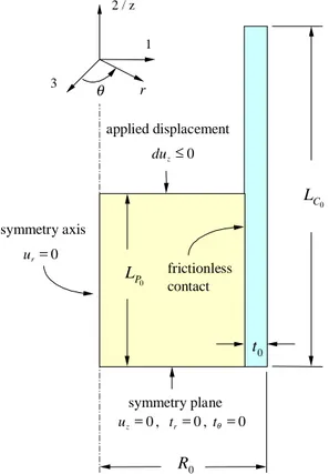
0 C L 0 P L 0 t 2 / z 1 3 θ r frictionless contact symmetry axis 0 = r u symmetry plane 0 , 0 , 0 = = = t tθ uz r 0 R applied displacement 0 ≤ z du
Fig. 1. Geometry and boundary conditions for the finite element simulation of the pellet cladding mechanical interaction, produced by the EDC-test. The origin of the coordinate systems is on the pellet/cladding mid-plane (i.e. the symmetry plane).
The geometry, used in the finite element simulation, is shown in Fig. 1 together with the boundary conditions. The symmetries with respect to the pellet/cladding axis and the mid-plane require the consideration of only one quarter of the axial section of the pellet and the cladding. Therefore LP0 and LC0 are the half-lengths of the pellet and the cladding, respectively. Cartesian, (x1, x2, x3), and cylindrical, (r, θ, z), coordinates are considered. x2/z is the symmetry axis and (x1 x3) is the symmetry plane, i.e. the pellet/cladding mid-plane. Note that, although not shown in Fig. 1, the origin of the coordinate system is on the symmetry plane.
The loading is applied by axial displacements, prescribed on the top pellet boundary, which result into the reduction of the length of the pellet and the development of compressive stresses in the pellet. Due to axial symmetry and material cohesion, the radial displacement, ur, is equal to zero along the symmetry axis. On the symmetry plane at
z=0, the axial displacements, u2, and the tangential traction, t1 and t3 are equal to zero. Between the pellet and the cladding, frictionless contact is considered. Note that, due to the expansion of zirconium oxide and hydride during formation, residual stresses exist in the cladding, before the performance of the EDC-test. These residual stresses are taken into account in the present analysis by allowing the oxide and hydride layers to expand, before the application of any displacement on the top boundary of the pellet. The isotropic volume expansion strain is 0.56 [5] for the oxide and 0.1636 for the hydride (e.g. [6]).
The zirconium alloy is assumed to be elastic-plastic. Young’s modulus and Poisson’s ratio are taken equal to 97 GPa and 0.4 respectively. For the plastic deformation, J2-flow theory is considered with power-law isotropic hardening:
( )
n p p H 1 0 0 1 + = = ε ε σ ε σ , (1)where σ and εp are Mises effective stress and the accumulated effective plastic strain, respectively. Also σ0 is the initial yield stress in tension, ε0 is a reference strain, equal to the elastic strain at yielding initiation in simple tension, and n is the hardening exponent. Calculations have been performed for hardening material with σ0 equal to 600MPa and n equal to 7.76 as well as for non-hardening material, (1/n=0). Note that the hardening exponent was derived from an ultimate tensile stress, in a simple tension test, equal to 780MPa. The oxide layer is assumed to be purely elastic with Young’s modulus Poisson’s ratio equal to 200 GPa and 0.3, respectively. The hydride layer is also purely elastic. In most of the calculations the elastic properties of the hydride are taken equal to those of the zirconium alloy. However, in order to estimate the effect of hydride elastic properties on cladding deformation and fracture, in one calculation, the properties, proposed in [7], are considered, i.e. 135.9 GPa for Young’s modulus and 0.32 for Poisson’s ratio.
The properties of the pellet polymer were calculated, by analyzing pellet compression tests, which were performed at room temperature in Studsvik Nuclear [4]. The pellet material is assumed to be elastic-plastic with Young’s modulus and Poisson’s ratio equal to 594 MPa and 0.474, respectively. Plastic behavior is again simulated, by using J2-flow theory and isotropic hardening. It was found that a combination of Johnson-Cook and linear hardening laws provide the best fitting to the experimental data:
( )
( )
p N P p K Hε σ ε σ = = 0+ , ≤0.05 p ε , (2a)( )
= 0+( )
0.05 +( )
0.05 1(
−0.05)
= N N− p P p KN K Hε σ ε σ , εp ≥0.05. (2b)The coefficient K and the hardening exponent N are equal to 19MPa and 0.22, respectively. The yield stress in compression, σP0, was found to be equal to 6.4MPa. No rate effects of the pellet material are considered. Indeed, the duration of the EDC-test is a fraction of a second (e.g. 0.05 to 0.2 s). Therefore, the relaxation of the material is negligible. The test, for a certain loading rate, could be adequately simulated, by using the stress-strain curve of the polymer, for the loading rate under consideration. In order to estimate the effect of polymer yield stress variation, due to different loading rates, additional calculations were performed with different values of polymer yield stress [4]. The normalized distributions of cladding radius change and total energy density, along the symmetry axis, did not vary. Therefore, the results on the deformation of the cladding do not depend on the rate-effects of the polymer, for the temperature and the rates under consideration.
For the finite element calculations ABAQUS/Standard (version 6.2) and the ‘hard’ contact model is used. Then, no pressure is applied while surfaces are not in contact, and any level of pressure could be applied, once contact is established. Details of the calculations are given in [8].
CLADDING DEFORMATION
Cladding external radius is a quantity, which is measured easily. Its distribution along the symmetry axis provides information on the plastic deformation of the cladding. It can also be associated with the development of stresses, during the deformation of the cladding. Therefore, it could facilitate the development of cladding failure criteria. Indeed, the distribution of the change of cladding external radius was measured along the symmetry axis, after the performance of experiments, which did not result into the fracture of the cladding [3]. Subsequently, a linear relation between the total energy density, averaged through cladding thickness, and the external radius change or equivalently the respective engineering hoop strain was assumed. This linearity assumption led to estimates on the critical total energy density for the cases of cladding failure [3]. The linear relation between total energy density and external radius change was found to be a good approximation in the case of a homogeneous elastic-plastic hardening or non-hardening cladding, after relatively large plastic deformation [4]. In the present work the effect of the external hydride and oxide layers is examined.
Fig. 2 shows the axial distribution of the change of cladding external radius in the case of a hydride layer thickness equal to 5% of the total cladding thickness. The results pertain to a hardening zirconium alloy. The radius change includes that, which is caused by hydride expansion during precipitation, ∆R1, i.e. before EDC-testing. On the symmetry plane this expansion leads to a radius increase of about 13 µm. In Fig. 3, ∆R1 has been subtracted from the total external radius change and the result has been normalized by the increase of the cladding external radius on the symmetry plane during testing. The position along the symmetry axis has also been normalized by the deformed pellet half-length, L . Note that as the engineering hoop strain on the symmetry plane, P
[
∆R( )
0 −∆R1( )
0]
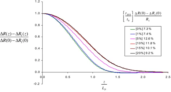
R1 , increases the normalized axial distribution of the external radius change tends to a limiting curve, which is valid after relatively largeplastic deformation. The normalized distribution depends strongly on the thickness of the external hydride layer (Fig. 4), when tH0 t0is in the range of 0.01 to 0.10. For tH0 t0equal to 0.01 or smaller the homogeneous cladding distribution is approached. Also, for tH0 t0 in the range of 0.10 to 0.20, no significant variation on the limiting distribution is observed. -1.E -0 4 0.E +0 0 1.E -0 4 2.E -0 4 3.E -0 4 4.E -0 4 5.E -0 4 6.E -0 4 7.E -0 4
0 .0E +0 0 2 .0E -0 3 4 .0E -0 3 6 .0E -0 3 8 .0E -0 3 1 .0E -0 2
0% 0 .2% 0 .7% 1 .3% 1 .9% 2 .6% 3 .2% 3 .9% 4 .6% 5 .3% 5 .9% 6 .6% 7 .3% 8% 8 .7% 9 .3% 1 0% 10 .7% 11 .3% 1 2% 12 .6% z (m ) ) m ( R ∆ 1 1(0) ) 0 ( R R R −∆ ∆ µm 2 . 13 ) 0 ( 1 = ∆R
Fig. 2. Axial distributions of the change of the cladding external radius, ∆R, under different levels of applied loading,
( )
( )
[
∆R0 −∆R1 0]
R1 . Position z is defined on the deformed configuration. (hardening zirconium alloy, 5% hydride layer thickness). -0 .2 0 .0 0 .2 0 .4 0 .6 0 .8 1 .0 1 .2 0 . 0 0 .2 0 .4 0 . 6 0 .8 1 .0 1 .2 1 . 4 1 .6 1 .8 2 .0 0 .2 % 0 .7 % 1 .3 % 1 .9 % 2 .6 % 3 .2 % 3 .9 % 4 .6 % 5 .3 % 5 .9 % 6 .6 % 7 .3 % 8 % 8 .7 % 9 .3 % 1 0 % 1 0 .7 % 1 1 .3 % 1 2 % 1 2 .6 % P L z 1 1(0) ) 0 ( R R R −∆ ∆ µm 2 . 13 ) 0 ( 1 = ∆R ) 0 ( ) 0 ( ) ( ) ( 1 1 R R z R z R ∆ − ∆ ∆ − ∆Fig. 3. Normalized axial distributions of the change of the cladding external radius during testing,
[
∆R( )
z −∆R1( )
z]
, under different levels of applied loading. Lp is the deformed pellet half-length. (hardening zirconium alloy, 5% hydride-0 .2 0 .0 0 .2 0 .4 0 .6 0 .8 1 .0 1 .2 0 .0 0 .5 1 .0 1 .5 2 .0 2 .5 [0 % ] 7 .3 % [1 % ] 7 .4 % [5 %] 1 2 .6 % [1 0 %] 1 1 .8 % [1 5 %] 1 0 .1 % [2 0 % ] 9 .2 % 1 1 0 0 (0) (0) R R R t tH ∆ −∆ P L z ) 0 ( ) 0 ( ) ( ) ( 1 1 R R z R z R ∆ − ∆ ∆ − ∆
Fig. 4. Fffect of hydride layer thickness on the limit axial distribution of the cladding external radius change (hardening zirconium alloy). -0 .2 0 .0 0 .2 0 .4 0 .6 0 .8 1 .0 1 .2 0 .0 0 .5 1 . 0 1. 5 2 .0 2 .5 [5 % ] 1 2 .6 % [5 % , NH] 1 4 .2 % [1 0 % ] 1 1 .8 % [1 0 % , NH] 1 3 .8 % 1 1 0 0 (0) (0) R R R t tH ∆ −∆ P L z ) 0 ( ) 0 ( ) ( ) ( 1 1 R R z R z R ∆ − ∆ ∆ − ∆
Fig. 5. Fffect of zirconium alloy hardening on the limit axial distribution of the cladding external radius change.
The effect of hardening of zirconium alloy on the limit axial distribution of the cladding external radius change is moderate, as shown in Fig. 5 for hydride layer thickness equal to 5% and 10% of the total cladding thickness. On the other hand, the effect of hydride elastic modulus as well as the effect of an adherent oxide layer (of thickness equal to 3
µm) is negligible[8]. The calculations with different hydride elastic modulus and an external oxide layer were performed for a hydride layer with thickness 0.1t .0
The axial distribution of the total energy density, when averaged through cladding thickness and appropriately normalized, also tends to a limit curve, after significant plastic deformation of the cladding (Fig. 6). In the normalized distribution, the total energy density, which is related to hydride formation before EDC-testing, has been subtracted.
According to Fig. 6, which presents all cases under consideration, the effect of hydride thickness is again significant. The limit curve for the normalized energy density distribution approaches again the respective distribution of a homogeneous cladding for hydride thickness less than 1% of the total cladding thickness. In this case, the linearity between external radius change and total energy density injected in the cladding, during testing, is confirmed:
( )
( )
( )
0( )
0( )
( )
0 1( )
( )
0 1 1 1 R R z R z R w w z w z w ∆ − ∆ ∆ − ∆ = − − . (3)Indeed the limit axial distributions of the external radius change and injected energy density, during testing, are approached by the same curve. If linearity is valid, then the critical energy density at failure can be estimated from the following relation [3]: ave cr ave cr R R w w ∆ ∆ ⋅ = . (4) cr R
∆ is the radius change on the symmetry plane at failure, wave is the average value of the injected energy density in
the cladding, during the test, and ∆Rave is the average external radius change, which can be calculated from the limit
distribution. Note that the limit distribution can be derived, by measuring the external radius change of the cladding, along the axis, once, in an experiment, which does not lead to failure [3].
As the hydride thickness increases, the radius change and the total energy density deviate from a linear relation. Then, the radius change and the energy density are generally related by a non-linear function, which depends on hydride layer thickness:
( )
( )
( )
( )
( )
( )
( )
( )
∆ − ∆ ∆ − ∆ = − − 0 0 1 1 1 1 ; 0 0 0 0 t t R R z R z R F w w z w z w H (5)Consequently (4) has to be appropriately modified. Function F, for a zirconium alloy and a hydride layer thickness, could be derived by finite element simulation of the EDC-test. Therefore, in the presence of a hydride layer of significant thickness, the critical energy density at fracture, could be estimated by combining experiments and numerical simulations.
Fig. 6. Limit axial distributions of average-through-thickness total energy density, injected in the cladding during EDC-testing. 0.0 0.2 0.4 0.6 0.8 1.0 1.2 0.0 0.2 0.4 0.6 0.8 1.0 1.2 1.4 1.6 1.8 2.0 [0%] 7.3% [1%] 7.4% [5%] 12.6% [5%, NH] 14.2% [10%] 11.8% [10%, NH] 13.8% [10%, E = 135.9 GPa] 10.7% [10%, incl. Ox.] 12.6% [15%] 10.1% [20%] 9.2% 1 1 0 0 (0) (0) R R R t tH ∆ −∆ ) 0 ( ) 0 ( ) ( ) ( 1 1 w w z w z w − − P L z
CLADDING FAILURE
The pellet-cladding mechanical interaction, during the EDC-test, leads to the development of tensile hoop stress in the hydride layer, which eventually overcomes the residual compressive hoop stress, due to hydride expansion during precipitation. Failure initiation of the cladding is expected to occur, when the hoop stress, which is also, at that instant, the maximum principal stress, reaches the strength of the hydride phase.
In the present section, a critical principal stress criterion is considered in order to predict hydride layer fracture and therefore cladding failure initiation. Hydride strength is not exactly known. An estimate of 700 MPa has been assumed based on the argument that the strength is proportional to hydride elastic modulus and empirical relation (16) in [9]. Fig. 7 shows the estimated engineering hoop strain on the symmetry plane at cladding failure initiation, for all cases under consideration. As expected, the increase of hydride layer thickness leads to embrittlement of the cladding and therefore to reduction of the engineering hoop strain at failure initiation. Indeed there is a reduction of 51% of the engineering hoop strain at fracture, from 7.7% to 3.8%, when the hydride layer thickness increases from 5% to 20% of the total cladding thickness. The critical strain predictions are larger than those expected in experiments [3], although no detailed comparisons have been made. However, as discussed in the following, the combined effects of non-hardening behavior of zirconium alloy, the existence of oxide layer and the larger elastic modulus of the hydride could lead to appreciable reduction of the critical hoop strain.
The external hydride layer breaks earlier when the zirconium alloy does not harden. Indeed after yielding, an increase of overall hoop stress in the cladding, due to an increase of the pressure applied by the pellet, is mainly taken by the external elastic hydride layer, which therefore reaches critical conditions earlier.
The expansion of the oxide, during formation, leads to reduction of the compressive hoop stress in the hydride. Therefore the critical hoop strain at hydride fracture, in the presence of an oxide layer, is smaller than that estimated without oxide.
It can be shown, by elementary elasticity analysis, that σθθ ≅
(
E 1−ν2)
⋅[
∆R( )
0 −∆R1( )
0]
R1, within the hydride layer. Then, when the elasticity modulus of the hydride increases, the critical principal stress at fracture is reached at a smaller engineering hoop strain.0 .0% 1 .0% 2 .0% 3 .0% 4 .0% 5 .0% 6 .0% 7 .0% 8 .0% 9 .0% 0% 5% 1 0% 1 5% 2 0% 2 5% Har de ning No n-har de ning Har de ning + O xid e la ye r Har de ning + E = 1 3 5.9 G P a f R R R 1 1(0) ) 0 ( −∆ ∆ 0 0 t tH
Fig. 7. External engineering hoop strain on the symmetry plane of the cladding at fracture as a function of hydride layer thickness.
The fracture estimates were also derived for hydride strength equal to 500 and 1000 MPa. The differences between the new engineering hoop strains at fracture and those of Fig. 7 are less than 5 % for all considered cases. Thus, the results of Fig. 7 are good estimates for a wide range of zirconium hydride strength.
Considering the same critical stress criterion, one may estimate the injected energy density on the symmetry plane, averaged through cladding thickness, at initiation of cladding failure. Fig. 8 shows this estimate for all cases under consideration. The effect of hydride thickness is strong. The injected energy density, at fracture, decreases by 63%, when the hydride thickness increases from 5% to 20% of the total cladding thickness. The hardening behavior of
the zirconium alloy is also important. Indeed, there is a difference of 30% in the injected energy density, at fracture, between a hardening and a non-hardening material.
0 . E+0 0 1 . E+0 7 2 . E+0 7 3 . E+0 7 4 . E+0 7 5 . E+0 7 6 . E+0 7 0 % 5 % 1 0 % 1 5 % 2 0 % 2 5 % Har d e nin g No n -h ar d e nin g Har d e ni ng + O xid e la ye r Har d en in g + E = 1 3 5 .9 G P a 0 0 t tH ) Jm ( ) 0 ( ) 0 ( 3 1 − −w w f
Fig. 8. Average-through-thickness of total injected energy density on the symmetry plane of the cladding at fracture as a function of hydride layer thickness.
ACKNOWLEDGMENT
The present study is part of the project on ‘Hydrogen Embrittlement and Fracture in Hydride Forming Metals’, which is financed by the Foundation for Knowledge and Competence Development (Project Grant Hög 2000, KK-Stiftelsen, Sweden). The project is performed with the cooperation of Studsvik Nuclear AB and Barsebäck Kraft AB.
REFERENCES
1. Lemoine, F., “High Burnup Fuel Behavior related to Fission Gas Effects under Reactivity Initiated Accidents (RIA) Conditions”, Journal of Nuclear Materials, Vol. 248, 1997, pp. 238-248.
2. Fuketa, T., Sasajima, H., Mori, Y. and Ishijima, K., “Fuel Failure and Fission Gas Release in High Burnup PWR Fuels under RIA Conditions”, Journal of Nuclear Materials, Vol. 248, 1997, pp. 249-256.
3. Grigoriev, V., Jakobsson, R. and Schrire, D., “Experimental Evaluation of Critical Strain Energy Density for Irradiated Cladding under Simulated RIA Conditions”, Proc. of ENS Topfuel 2001, Stockholm, Sweden, May 2001. 4. Dufourneaud, O., Varias, A.G., Grigoriev, V., Jakobsson, R. and Schrire, D., “Elastic-Plastic Deformation of a Nuclear Fuel Cladding Specimen under the Internal Pressure of a Polymer Pellet”, Proc. of Fifth World Congress on Computational Mechanics, Vienna, Austria, July 2002.
5. Chung, H.M., “Fundamental Metallurgical Aspects of Axial Splitting in Zircaloy Cladding”, Proc. of 2000 Topical Meeting on Light Water Reactor Fuel Performance, Park City, Utah, USA, April 2000.
6. Varias, A.G. and Massih, A.R., “Simulation of Hydrogen Embrittlement in Zirconium Alloys under Stress and Temperature Gradients”, Journal of Nuclear Materials, Vol. 279, 2000, pp. 273-285.
7. Kuroda, M., Yoshioka, K., Yamanaka, S., Anada, H., Nagase, F. and Uetsuka, H., “Influence of Precipitated Hydride on the Fracture Behavior of Zircaloy Fuel Cladding Tube”, Journal of Nuclear Science and Technology, Vol. 37, 2000, pp. 670-675.
8. Ménager, Y., “Effect of a Zirconium Hydride External Layer on the Embrittlement of Nuclear Fuel Cladding in Light Water Reactors”, Report US-02-06-02, Malmö University, Malmö, Sweden, 2002.
9. Shi, S.-Q. and Puls, M.P., “Criteria for Fracture Initiation at Hydrides in Zirconium Alloys I. Sharp Crack Tip”, Journal of Nuclear Materials, Vol. 208, 1994, pp. 232-242.