34
ISBN: 978-91-88898-64-7
Experimental Analysis and Numerical Modelling of
Post-Tensioned CLT Shear Walls with Energy Dissipators
Zhiyong Chen* and Marjan Popovski
FPInnovations, 2556 East Mall, Vancouver, BC V6T 1Z4, Canada
zhiyong.chen@fpinnovations.ca and marjan.popovski@fpinnovations.ca
The prestressed-laminated timber (Pres-Lam) system, developed in New Zealand, is a low damage innovative wood-hybrid system that utilizes post-tensioned (PT) mass timber components along with various types of energy dissipators. For implementation of Pres-Lam system in North America, the in-plane lateral-load response of PT only and Pres-Lam Cross Laminated Timber (CLT) shear walls was investigated at FPInnovations [1].
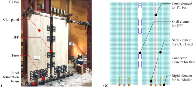
A total of 14 different PT only and Pres-Lam CLT walls in four configurations were tested under monotonic and reversed cyclic loading. A coupled Pres-Lam CLT shear wall with axial energy dissipators (fuses) at the bottom and U-shaped flexural plates (UFPs) between the two CLT panels is shown in Figure 1a. PT only and Pres-Lam CLT shear walls had nonlinear behaviour with a decompression point corresponded to the state when the PT force started to increase. Pres-Lam CLT shear walls had higher resistance, maximum lateral drift and energy dissipation compared to PT only walls. The test results also showed that the behaviour of the Pre-Lam CLT shear walls can be de-coupled and a “superposition rule” can be applied to estimate the stiffness and resistance of such systems. Yielding and buckling of the fuses occurred at the early stage of loading as designed, and localized crushing of wood at the bottom ends of panels happened when the lateral drift was at or beyond 2.5%.
(a) (b)
Figure 1: Coupled Pres-Lam CLT Shear Wall with Fuses and UFPs: (a) Tested Specimen; and (b) FE model
Specific numerical models of PT only and Pres-Lam CLT walls were developed in general purpose finite element (FE) software package, ABAQUS. The CLT panels were modelled using shell elements with adequate strength and stiffness properties in each orthogonal direction. The steel post-tensioning cables and the UFPs were modeled using truss and shell elements, respectively, with the strength and the stiffness properties of the steel used in the testing program. The fuses were modelled using connector elements with the hysteresis loops of fuses obtained in the testing program. The foundation was modeled using rigid elements. “Softened” contact with friction was adopted in the interaction between the CLT panels and the foundation. The fuses were connected to the CLT panels and the foundation using multiple point constraints (MPC) technique. Using MPC, UFPs were also connected to the CLT panels in the coupled wall configuration (Figure 1b). The PT force applied to the wall was achieved by lowering the temperature of the PT bar which will shorten correspondingly. The response of the developed models agreed well with the experimental results of the tested wall configurations. The influence of the PT force level, the aspect ratio of the wall panels, the spacing and number of energy dissipating devices on the response of the system were investigated using the verified models. The testing and modelling results gave a valuable insight on the behaviour of the PT only and Pres-Lam CLT shear walls under in-plane lateral loads.
References
[1] Z. Chen, M. Popovski, P. Symons: Advanced Wood-Based Solutions for Mid-Rise and High-Rise Construction: Structural Performance of Post-Tensioned CLT Shear Walls with Energy Dissipators. FPInnovations Technical Report (301012204), 2018.