Research
Effect of weld repairs on residual
stresses in nickel base dissimilar
metal welds
2017:22
Authors: Etienne BonnaudSSM perspective
Background
The driving force for crack growth near welds in nuclear application piping may arise from weld residual stresses. Experience from non-destructive examination show that cracks in dissimilar metal welds are often found near weld repairs. The repair welding may affect the residual stresses through e.g. increased tensile stresses and increased plastic straining on the surfaces of the piping in contact with the light water reactor environment. This may in turn reduce the margin towards initia-tion of stress corrosion cracking.
Objectives
This study investigates how weld residual stresses in dissimilar metal welds are affected by weld repairs for select cases relevant to Swedish nuclear power plants.
Results
The most common configuration of dissimilar metal weld connect-ing ferritic nozzles to safe-ends in Swedish nuclear power plants were chosen for further investigation. Five significant cases of weld repairs are identified for that particular configuration of dissimilar metal weld, three inside and two outside repairs for pipes of different sizes.
The weld residual stresses for the five cases are investigated by numeri-cal simulation with two dimensional axi-symmetric assumptions. Con-clusions are drawn based on comparison of the weld residual stresses before and after weld repair.
The results show that the inside repairs generate high tensile stresses at the inside surface. This is generally unfavourable since stress corrosion cracking would be prevented if stresses at the surface were compressive. Therefore, careful consideration is recommended before performing inside weld repairs to avoid introducing unnecessary plastic strains from welding and high tensile stress after repair as driving forces for stress corrosion cracking.
The effect from an inside repair was similar for both the thin and thick pipe cases studied. Sensitivity studies were performed with respect to heat input and repair thickness, and the results show small effects. Repair welding from the pipe outside surface results in small changes of the residual stress field compared to the unrepaired weld. However, for deep repairs from the outside, the material at the pipe inside surface can be subjected to a significant increase in plastic hardening. Material highly hardened from plastic deformation at welding is generally more susceptible to initiation of stress corrosion cracking, provided that the material is in a region of tensile stress and exposed to the corrosive envi-ronment. The sensitivity to an offset between the outside repair and the original weld was investigated, and the effect was found to be small.
Need for further research
Since the current research focused on long weld repairs which were investigated by use of axi-symmetric modelling, a possibility for further research is to use three-dimensional modelling and investigate effects of short repairs and local effects. Local effects will be present at the begin-ning and end of repairs, and the extent of these localised effects for residual stresses can be evaluated, together with its influence on crack growth and fracture margin. This would clarify for which situations an axi-symmetric assumption is valid for the determination of crack growth rate and fracture margin.
Project information
Contact person SSM: Daniel Kjellin Reference: SSM2015-925
2017:22
Authors: Etienne Bonnaud, Jens Gunnars Inspecta Technology AB, Stockholm
Effect of weld repairs on residual
stresses in nickel base dissimilar
metal welds
Effect of weld repairs on
residual stresses in nickel base
dissimilar metal welds
Authors
Etienne Bonnaud and Jens Gunnars
(Inspecta Technology AB, Report No. 5000540, Rev. 0)
Sammanfattning
Effekten av svetsreparationer har undersökts för rörsvetsar av nickelbasmaterial. En inventering har utförts av orsaker till
svetsreparationer i omkretssvetsar och en översikt ges av positioner och utförande för olika typer av reparationer. Med hjälp av numerisk svetssimulering analyseras några valda svetsreparationer avseende inverkan på svetsegenspänningar och plastisk töjning.
Inventeringen av svetsreparationer inriktas mot rörsvetsar vid stutsar. Reparation från insidan kan användas för att avlägsna påträffade driftinducerade defekter, men även som en förebyggande åtgärd för att ersätta befintligt svetsgods med en legering med större motstånd mot initiering av spänningskorrosion. Under tillverkningen används i regel reparation från utsidan för att avlägsna defekter, och endast för rör med mycket stor diameter utförs reparationer från insidan.
Inverkan på restspänningsfältet från långsträckta svetsreparationer har undersökts för olika invändiga och utvändiga reparationer. Resultaten visar att invändiga svetsreparationer ger höga dragspänningar vid rörets insida, där de var kompressiva innan reparationen. Detta är ogynnsamt eftersom initiering och tillväxt av spänningskorrosion förhindras om spänningarna vid den medieberörda ytan är
kompressiva. Svetsreparationer från rörets utsida ger små förändringar av restspänningsfältet. Djupa utvändiga reparationer kan dock
medföra en signifikant ökning av plastiskt hårdnande i materialet vid den medieberörda ytan, vilket kan minska motståndet mot initiering.
Effects of weld repairs on residual stresses
in nickel base dissimilar metal welds
Summary
Effects of repair welding in nickel base dissimilar metal welds are investigated. The causes to different types of weld repairs and their respective position and configuration are summarised. The effect on weld residual stress and plastic strain are then investigated by numerical simulation for selected weld repairs.
Weld repairs in nozzle-to-piping butt welds are reviewed with respect to different configurations and causes. Repairs at the pipe inside surface may be performed to remove a defect found in service, or as a preventive measure to protect susceptible material. Repairs from the pipe outside surface are performed when removing defects found during manufacturing. Inside weld repairs are not performed during manufacturing, except for very large diameter piping.
The effect on the residual stress profile from long weld repairs at the inside and outside surface are studied for different pipe geometries. The results show that the inside repairs generate high tensile stresses at the inside surface, while being in compression before repair. This is generally unfavourable since stress corrosion cracking can be
prevented if stresses at the surface are compressive. Repair welding from the pipe outside surface results in very small changes of the residual stress field compared to the original weld. However, for deep repairs from the outside, the material at the pipe inside surface receive a significant increase in plastic hardening, which may increase
susceptibility to stress corrosion crack growth.
Content
1 Background ... 4
2 Overview of weld repairs ... 6
2.1 Repair at manufacturing ... 6
2.2 Repair of components in service ... 7
2.3 Preventive repairs ... 7
2.4 Outside and inside surface repairs ... 8
3 Earlier result for weld repair in DMW ... 8
4 Analysed weld repair cases ... 11
5 Modelling ... 14 5.1 Analysis steps ... 14 5.2 Material properties ... 15 5.3 Welding parameters ... 15 5.4 Bead sequence ... 15 5.5 Pressure test ... 16 6 Results ... 17
6.1 Inside repair results ... 17
6.2 Inside repair - heat input sensitivity (t = 12.7 mm) ... 21
6.3 Inside repair - repair thickness sensitivity (t = 40.5 mm) ... 22
6.4 Outside repair results ... 23
6.5 Outside repair - offset sensitivity (t = 40.5 mm) ... 26
7 Conclusions ... 28
8 Suggestions for further work ... 29
9 References ... 30
Appendix A – Material properties ... 32
Appendix B - Results ... 36
1 Background
Repair welding may cause residual stresses and strains that have significant effect on degradation mechanisms such as stress corrosion, fatigue and creep. This study focuses on repairs in nickel base dissimilar metal welds which can be susceptible to stress corrosion cracking. Stress corrosion cracking is a degradation mechanism which in nuclear power plants is taken into consideration by developing adapted
inspection programs and other preventive measures. Stress corrosion cracking may occur for certain combinations of unfavourable
environment, susceptible material and tensile stress. Further the
susceptibility to stress corrosion cracking is known to be influenced by hardening, plastic strains and their localization at grain boundaries. Information of this type are considered when developing inspection programs. Since tensile residual stresses are a primary driver for stress corrosion cracking, it is important to understand the effect of repairs on residual stress fields, in order to ensure appropriate inspections and other measures.
Operating experience indicate a correlation between stress corrosion cracks detected in nickel base welds and areas where weld repairs have been carried out. This may be related to increased tensile stresses and plastic strains at the inside surface for certain types of weld repairs. Effects on the microstructure due to additional temperature cycling from a repair weld could also be contributing.
Repair welding is performed when unacceptable defects are detected during manufacturing inspection. Another situation for repair welding is when degradation is found during in-service inspections. An additional group of repair welds are those performed as a preventive measure for welds susceptible to stress corrosion cracking. Outside weld overlays can be used with the purpose to reduce tensile residual stresses at the inside surface. Inlay welds of more resistant material are sometimes applied at the surface exposed to the corrosive environment, as a barrier to stress corrosion cracking.
Different effects from weld repairs have been studied for various types of repair geometries and materials. Numerical analysis of residual stress fields after repairs are presented in e.g. [1, 2], residual stress
measurement results for some cases are given in [3-5], microstructure effects are discussed in e.g. [6], and consequences with respect to
damage tolerance are studied in [7] for an inlay repair. This investigation focuses on numerical analysis of the effect from different types of repairs
Short repairs are known to generate high tensile residual stresses locally at the repair due to high constraints, but also long repairs along a weld may result in significant tensile stresses. Repairs from the inside and outside of a pipe can result in different effects at the inside surface, also dependent on the depth of the repair. Since weld residual stresses and strains have large influence on stress corrosion cracking (SCC), it is important to analyse the effect from different types of weld repairs, to improve the understanding of which repairs that can be disregarded and which need to be considered.
Situations with high tensile stress at the inside surface exposed to the corrosive environment may promote initiation of stress corrosion cracks. However, equally important is the continued growth of an initiated crack, which to a large extent is dependent of the residual stress field in the pipe wall. Thus, for fracture mechanical evaluations of crack growth it is important with knowledge on through the thickness residual stress distributions and how they can be affected by different types of weld repairs.
The distribution of residual stresses and strains at weld locations can been analysed numerically by finite element simulation. Several projects have been performed recently for development and validation of weld residual stress modelling. This has resulted in important understanding and improvements in numerical procedures, heat source modelling and material modelling and data [9, 10, 11]. Recent validation projects for nickel-base welds confirm good agreement between detailed modelling and accurate measurements, see for example [12]. This knowledge can be used for investigation of weld repairs in pipe butt welds.
Long repairs can provide driving force for growth to long stress corrosion cracks, and may also influence the damage tolerance. Short repairs can promote initiation of SCC, but on the other hand their significance can be smaller since the change in the residual stress field is limited to small area and has less possibility to provide driving force for growth to a long SCC crack. Further, an important case is preventive inlay repairs around the inside circumference, and they resemble very long repairs. Long repairs may also appear in manufacturing due to multiple defects or deep defects, requiring more extensive material removal. The conclusion is that effects from long repairs are important to understand, and the current investigation is focused on axi-symmetric analyses of long
circumferential repairs.
Repair welds may in some cases result in significant changes of the residual stress field compared to the unrepaired weld. This is important information to fracture mechanical evaluations performed to determine necessary inspection intervals. Understanding of the stress field resulting
from different repairs can also provide important input for assessment of the efficiency and robustness of different alternative preventive repairs. The purpose of this study is to evaluate the effect of repair welding for nickel base DMWs. Different types of repair welding are summarized in an overview. The effect of different types of weld repairs on weld residual stress and plastic strain are investigated by numerical analysis.
Weld residual stresses profiles at DMWs are evaluated before and after weld repairs, for different repair positions and sizes. The effect is expected to depend on the pipe geometry and the existing weld residual stresses prior to repair. Cases are selected for analysis to investigate repairs in nickel-base butt welds in pipes of different size and for different types of repairs.
2 Overview of weld repairs
This section summarizes different types of weld repairs with respect to causes for them, their position and configuration.
2.1 Repair at manufacturing
Different types of defects can occur during welding, and manufacturing inspections are performed to assure that only defects that are small enough to be tolerable are left. Small defects are inherent to all welds and acceptable. General guidelines may be used to assess if a defect is
tolerable, or alternatively more detailed assessments of tolerable size can be done case-by-case with the purpose to avoid unnecessary and
sometimes adverse repair work. Defect types that may occur includes pores, oxides, cold laps, lack of fusion and cracks. Lack of fusion and multiple linear pores may form long defects along the welding direction. Surface defects or internal defects may be detected by visual inspection or non-destructive testing (NDT) as penetrant, magnetic particle, radiographic and ultrasonic testing.
If a weld fails at inspection, the defects is located and the extent reviewed from the NDT results prior to removal. The defect is removed from the nearest accessible surface. For piping, the repairs are generally performed from the outside, except for large pipe diameters. For weld root defects inside repairs may be preferred, but can require rework if not possible. The defect is removed by grinding and penetrant testing alternatingly, until the defect is removed and some additional millimetres. Testing is performed to confirm that crack like defects are entirely removed.
detected defect (in the middle of the weld or at the fusion line), the repair is either centred at the original weld or is laterally offset relative to the original weld. Sometimes also welding is performed to improve the root pass.
A repair procedure is prepared to minimize the effect of the repair, considering aspects as impact on base material, in-process inspections and final properties, for example advising to use lower currents. High tensile residual stress is a critical factor to initiation of stress
corrosion cracking. Local short repairs are known to generate high tensile residual stresses, but also long repairs along the welding direction may result in high residual stresses.
2.2 Repair of components in service
Equipment in operation is generally subjected to different types of degradation due to the loading and environment, for example corrosion, stress corrosion cracking and fatigue cracking. Service-induced defects can occur and they are generally surface defects. In nuclear plants, defects usually occur at the pipe inside subjected to the reactor water environment, however defects may also occur at the pipe outside. Recurrent inspections are performed in order to detect damage and defects before they grow to unacceptable size. If a defect is found, it may be possible to safely continue operation for a limited time, as assessed case-by-case. This can ensure sufficient time for preparation of a high quality repair. The position and size of a detected defect is characterized in detail by NDT. If the size of the defect is unacceptable, the defect is removed from the nearest accessible surface, usually from the inside. Testing is performed after removal to confirm that the entire crack is removed. A repair procedure is prepared to minimize the effect of the repair welding.
2.3 Preventive repairs
Corrosion resistant weld material is sometimes deposited on surfaces as a protective layer at areas sensitive to the service environment.
In nuclear plants some welds can be susceptible to stress corrosion cracking from the inside surface at welds. Sometimes inlay welds are applied as a preventive measure for susceptible nickel base dissimilar metal welds, see e.g. [13]. The inside area with susceptible material is machined or ground, and the groove is filled with resistant weld metal. The depth of the inlay weld (or repair weld) usually corresponds to a few layers of weld beads.
Other types of preventive weld repairs are designed with the purpose to achieve compressive residual stresses at the inside surface, e.g. by an outside weld overlay, by surface treatments for stress improvement, or by optimized design of welds.
2.4 Outside and inside surface repairs
We may summarize the occurrence of outside and inside repairs at nickel base dissimilar metal welds in nuclear nozzles and piping as follows. Repairs that were performed during manufacturing are generally weld repairs from the outside surface. Inside repairs are only likely for very large diameter pipes. For small diameter pipes the weld is usually cut away and fully rebuilt. Repairs performed to remove service-induced defects are in most cases weld repairs at the inside surface. Sometimes inlay welds at the inside surface are used as a preventive measure.
3 Earlier result for weld repair in DMW
The report [12] presents recent numerical results for a nickel base dissimilar metal weld between a nozzle and a pipe with thickness
t = 45 mm, inner radius R = 142 mm and ratio R/t = 3.2. The aim of
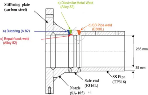
the project was to validate numerical prediction of weld residual stresses by a comparison to detailed experimental measurements on a mock-up. Twelve organizations from different countries participated in the project lead by US NRC. The comparisons were performed blind, that is after the submission of numerical prediction from each organization. The mock-up geometry is shown in Fig 3.1 and includes welds between a ferritic nozzle, nickel base safe-end and a stainless steel pipe. The welds were manufactured in a particular sequence and an intermediate result illustrate the effect of an inside inlay repair. The manufacturing sequence was as follows. The carbon steel nozzle was buttered with Alloy 82. After heat treating and machining the butter, 40 passes were deposited with Alloy 82 to make up the main dissimilar metal weld, b) in Fig. 3.1. Next, the weld root area of the main weld was machined, and then the circumferential inside repair were welded by Alloy 82, weld c) in Fig. 3.1. This corresponds to an inside inlay repair. The main DMW butt weld is 35 mm thick and the repair/back weld is approximately 10 mm deep after final machining. After this stage, residual stress measurements were made.
Fig. 3.1: Sketch of the dissimilar metal weld mock-up; c) is the inside repair/back weld.
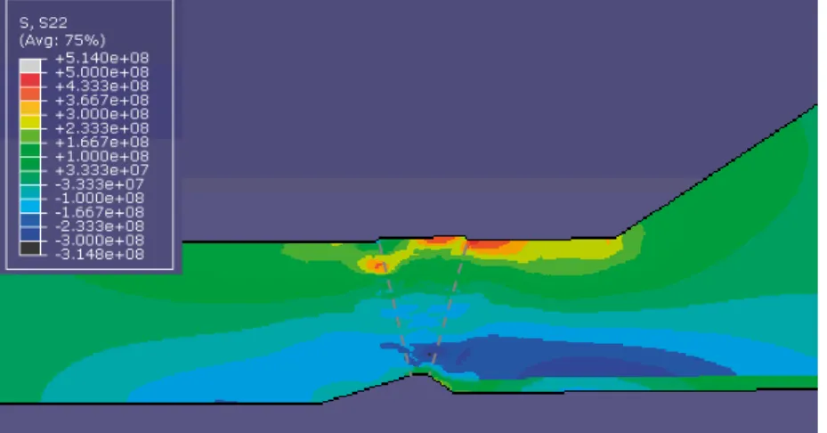
Figure 3.2 shows the axial stress distribution a) after welding the main dissimilar metal weld, and b) after the inside repair. Comparison between Fig. 3.2a and Figs. 3.2b shows that the repair results in tensile axial residual stress at the inside surface, from being compressive before in this case. After the repair the conditions for initiation of SCC may be fulfilled. However, for this particular case the compressive zone in the middle of the weld may still arrest a potential crack. In the project [12] the result in Fig. 3.2b, at the stage after the repair weld, was validated to detailed measurements. The results from Inspecta were among them with closest agreement to the
Fig. 3.2a: Axial residual stress after welding the main dissimilar metal weld. Stress in Pa.
4 Analysed weld repair cases
Effects of different types of weld repairs are examined by detailed analysis of five selected cases. Repairs in nickel base dissimilar metal welds are studied, based on the state for unrepaired nozzle-to-piping butt welds in Swedish plants [8]. Three inside repairs and two outside repairs in pipes of different size were selected. The analysis start by simulation of the weld residual stress field in the existing weld, prior to repair. Changes in the residual stresses and strains after repair welding are evaluated for the different repair positions and sizes. In [8] residual stresses are analysed for dissimilar metal weld configurations existing in Swedish plants, and six main types of DMW configurations are identified. In the present work we assume the Type I configuration in that report, which is the most common configuration for connecting ferritic nozzles to safe-ends.
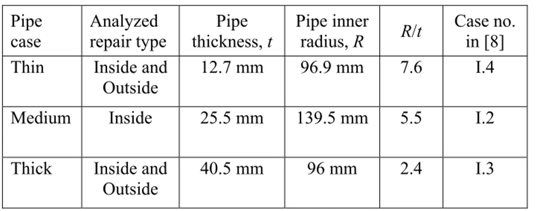
The geometries studied are illustrated in Figure 4.1 for inside repairs and in Figure 4.2 for outside repairs. The selected cases start from the same geometry and material data as specified in [8]. Basic parameters for the cases are summarized in Table 1. Inside repairs are analysed for three sizes of pipes, denoted thin, medium and thick with reference to the wall thicknesses. Outside repairs are analysed for two sizes of pipes, thin and thick.
The inside repairs studied are based on information on dimensions and welding specifications provided by Forsmark for preventive inlay weld repairs that they have implemented. Dimensions of the analysed inside repairs are listed in Table 2 and are based on information in [14-19]. The number of weld beads deposited is estimated for each case based on the specified geometry and number of layers. The dimensions of the studied outside repairs were selected after discussions [20] on removal of manufacturing defects. Defects are in general removed from the nearest surface, which imply a maximum repair depth of 50% of the thickness depth, provided that access is possible from both surfaces. For piping it is usually only possible to perform the repair from the outside, except for large pipe diameters. It was decided to study cases of deep repairs from the outside, in a thin and thick pipe. Material were removed to a depth of 80% of the wall thickness. Studies are performed for outside repairs centred at the middle of the original weld and for repairs centred at the fusion
The repairs analysed are assumed to be long and axi-symmetric modelling is applied. Repairs carried out to remove defects are limited to the length of the defect, and can be short or long compared to the weld width. However as discussed earlier, it is important to study long repairs because they may contribute to the growth of longer cracks. Further, preventive repairs to improve the stress state or to replace susceptible weld material by less SCC sensitive material are always carried out on the entire circumference.
In order to study local effects at the beginning and the end of a weld repairs, or at short repairs, three dimensional simulations would be required, but this is not the focus in the present investigation.
The influence of these weld repairs on residual stress profiles will be analysed by detailed numerical modelling.
Table 1: Geometrical parameters. Pipe
case Analyzed repair type thickness, t Pipe Pipe inner radius, R R/t Case no. in [8] Thin Inside and
Outside 12.7 mm 96.9 mm 7.6 I.4 Medium Inside 25.5 mm 139.5 mm 5.5 I.2 Thick Inside and
Outside 40.5 mm 96 mm 2.4 I.3
Table 2: Dimensions of inside repairs. Pipe
case thickness, t Pipe depth, d Repair length, L Repair Number of beads
Thin 12.7 mm 3.5 mm 30 mm 24
Medium 25.5 mm 3.6 mm 30 mm 24 Thick 40.5 mm 3.8 mm 54 mm 45
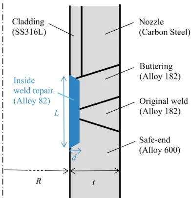
Fig. 4.1: Geometry of an inside weld repair (inlay weld) at a dissimilar metal butt weld for a pipe of radius R and thickens t.
Fig. 4.2: Geometry of an outside weld repair in a dissimilar metal butt weld for a pipe of radius R and thickens t.
Buttering (Alloy 182) Outside weld repair (Alloy 182) Cladding
(SS316L) Nozzle (Carbon Steel) Buttering (Alloy 182) Inside weld repair (Alloy 82) Original weld (Alloy 182) Original weld (Alloy 182) Safe-end (Alloy 600) Cladding (SS316L) L d t Nozzle (Carbon Steel) Safe-end (Alloy 600) t R R
5 Modelling
Detailed numerical analysis is used to study the effect from weld repairs for dissimilar metal welds. The modelling method applied in the welding simulation was developed and validated in [9, 10, 12].
The heat flow from the welding process is analysed with thermal modelling, followed by thermo-mechanical analysis. Generally best estimate data are used for influencing parameters and material properties.
In reference [8] residual stresses are analysed for nickel base
dissimilar metal weld configurations in Swedish plants. The present work build on this study by assuming that the original weld for the selected cases is deposited as in [8], and then different repair welding is modelled and evaluated. The modelling and data applied in the welding simulations of the nickel base DMWs are described in [8]. Post weld heat treatment is not applied and is thus not simulated.
5.1 Analysis steps
Welding and related manufacturing steps are analysed. The analysis start by simulation of the original weld and is followed by simulation of the repair welding. The simulated sequence is described below.
Inside repairs:
1. Welding of original weld a. Weld joint preparation
b. Welding based on welding specification c. Weld cap grinding and Pressure test 2. Repair welding
a. Mapping of results from original to repair weld model b. Material removal for the repair
c. Welding based on welding specification d. Repair grinding
Outside repairs:
1. Welding of original weld a. Weld joint preparation
b. Welding based on welding specification c. Weld cap grinding
2. Repair welding
a. Mapping of results from original to repair weld model b. Material removal for the repair
5.2 Material properties
The transient temperature cycles during the welding process imply that material modeling and material properties as a function of temperature is required up to very high temperatures. Physical and mechanical material properties for the materials as a function of temperature are described in Appendix A.
The material properties are the same as used in reference [8].
5.3 Welding parameters
The outside repairs are welded using the same welding process and welding parameters as for the original welds, see [8] for details. The welding process is Shielded Metal Arc Welding (SMAW). Gas Tungsten Arc Welding (GTAW) is generally used for the root pass. The number of passes and the heat input supplied by the welding arc is estimated using WPS information.
The welding parameters applied for the inside repairs (inlay welds) are estimated from the information in [14-16]. GTAW (or TIG) is
commonly applied for inlay welds and lower heat input and smaller beads are applied in the simulation of the inside repairs. The heat input was estimated based on the welding parameters; voltage 11.5 V, base current 100 A, and travel speed 100 mm/min. The bead cross section was approximately 2 mm * 4 mm. The inter-pass temperature applied is 20 °C, which is conservative with respect to residual stress levels.
5.4 Bead sequence
The bead sequence for the outside repair welding follows the bead sequence for the original weld. For each layer of the weld the last bead is performed at the weld centre, see illustration in Figure 5.1.
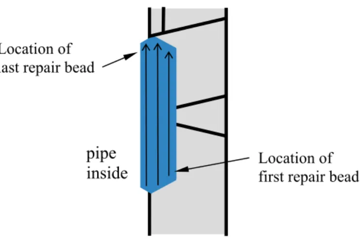
For the inside repairs beads are deposited in three layers, see Figure 5.2. The third layer (capping) is removed after welding.
Location of last repair bead
pipe inside
Fig. 5.1: Sketch of bead sequence for an outside weld repair to 80% depth of the pipe wall thickness.
Fig. 5.2: Sketch of bead sequence for weld repairs at pipe inside.
5.5 Pressure test
Pressure test can result in relaxation of weld residual stresses and its effect has to be taken into account in the simulations.
Original welds with repairs done during manufacturing are subjected to pressure test. In this investigation outside repairs are always assumed to be made during manufacturing and therefore pressure test is simulated with the outside repair included.
All inside repairs are assumed to be made after the plant is taken into operation, as a preventive measure or as a result of detection of
defects. This means that pressure test is only simulated for the original weld, before the inside repair. The test pressure was 110 bar.
Location of last repair bead
Location of first repair bead
pipe inside
6 Results
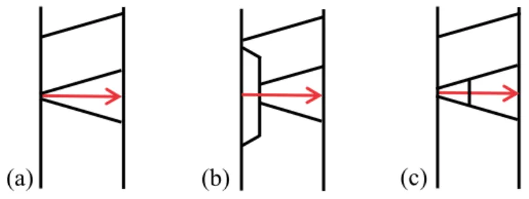
The change in the stress distribution through the thickness are presented for different weld repairs. Results are presented for a path along the centre line of the weld. The coordinate is zero at the pipe inside, see sketches in Fig. 6.1.
In this section axial and hoop stresses through the thickness are presented after the original welding and after the repair. Field plots of axial and hoop stresses as well as effective plastic strain are presented in Appendix B. All results are extracted at room temperature.
Fig. 6.1: Definition of weld centre line path for (a) original weld, (b) inside repair and (c) outside repair.
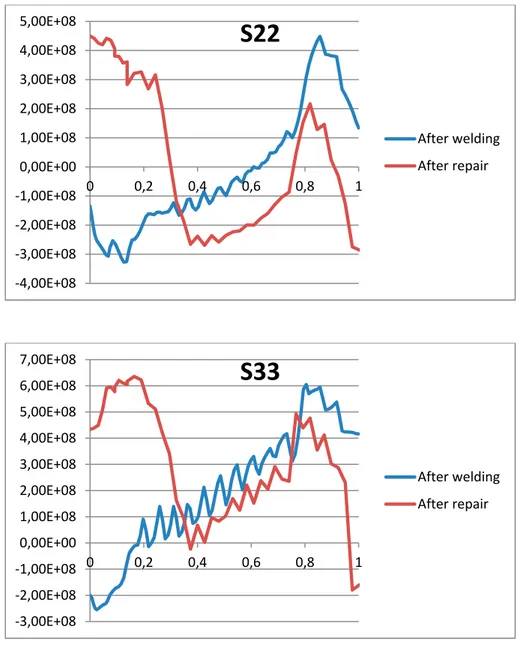
6.1 Inside repair results
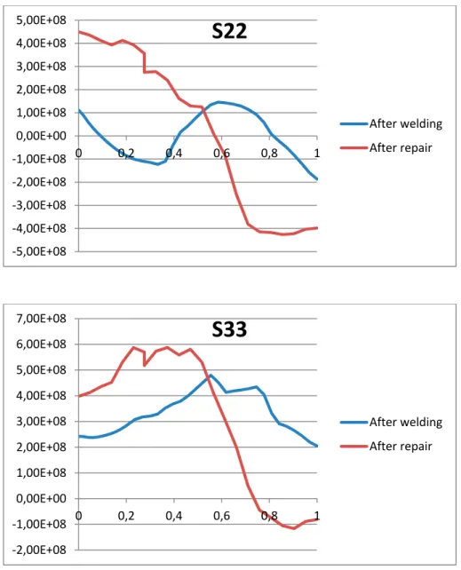
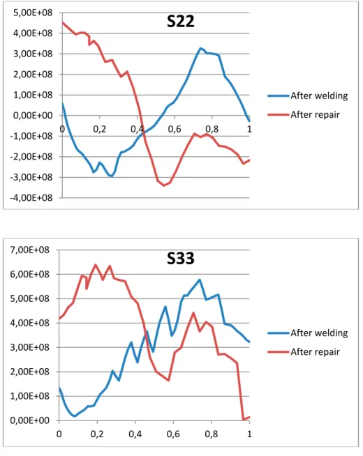
Figures 6.1, 6.2 and 6.3 show the results for inside weld repairs in DMWs of increasing thickness; 12.7 mm, 25.5 mm and 40.5 mm. For all three pipe thicknesses the axial stresses S22 at the inside region increase from slightly tensile or slightly compressive to highly tensile. The compressive region nearby moves further away from the inside surface. Material shrinkage and inward bending in the weld repair section are responsible for this axial stress increase.
The hoop stresses S33 increase for all three thicknesses from slightly tensile or slightly compressive to highly tensile at the inside surface, see Figs. 6.1, 6.2 and 6.3. Material shrinkage is prevented in the circumferential direction by the surrounding material, which causes hoop stress to increase at the inside weld repair.
(b)
Fig. 6.1: Inside repair, axial (S22) and hoop (S33) stresses,
t=12.7 mm. Distance is normalized by the thickness and
stress values are in Pa.
‐5,00E+08 -4,00E+08 -3,00E+08 -2,00E+08 -1,00E+08 0,00E+00 1,00E+08 2,00E+08 3,00E+08 4,00E+08 5,00E+08 0 0,2 0,4 0,6 0,8 1
S22
After welding After repair -2,00E+08 -1,00E+08 0,00E+00 1,00E+08 2,00E+08 3,00E+08 4,00E+08 5,00E+08 6,00E+08 7,00E+08 0 0,2 0,4 0,6 0,8 1S33
After welding After repairFig. 6.2: Inside repair, axial (S22) and hoop (S33) stresses,
t=25.5 mm. Distance is normalized by the thickness and
stress values are in Pa.
-4,00E+08 -3,00E+08 -2,00E+08 -1,00E+08 0,00E+00 1,00E+08 2,00E+08 3,00E+08 4,00E+08 5,00E+08 0 0,2 0,4 0,6 0,8 1
S22
After welding After repair 0,00E+00 1,00E+08 2,00E+08 3,00E+08 4,00E+08 5,00E+08 6,00E+08 7,00E+08 0 0,2 0,4 0,6 0,8 1S33
After welding After repairFig. 6.3: Inside repair, axial (S22) and hoop (S33) stresses,
t=40.5 mm. Distance is normalized by the thickness and
stress values are in Pa.
-4,00E+08 -3,00E+08 -2,00E+08 -1,00E+08 0,00E+00 1,00E+08 2,00E+08 3,00E+08 4,00E+08 5,00E+08 0 0,2 0,4 0,6 0,8 1
S22
After welding After repair -3,00E+08 -2,00E+08 -1,00E+08 0,00E+00 1,00E+08 2,00E+08 3,00E+08 4,00E+08 5,00E+08 6,00E+08 7,00E+08 0 0,2 0,4 0,6 0,8 1S33
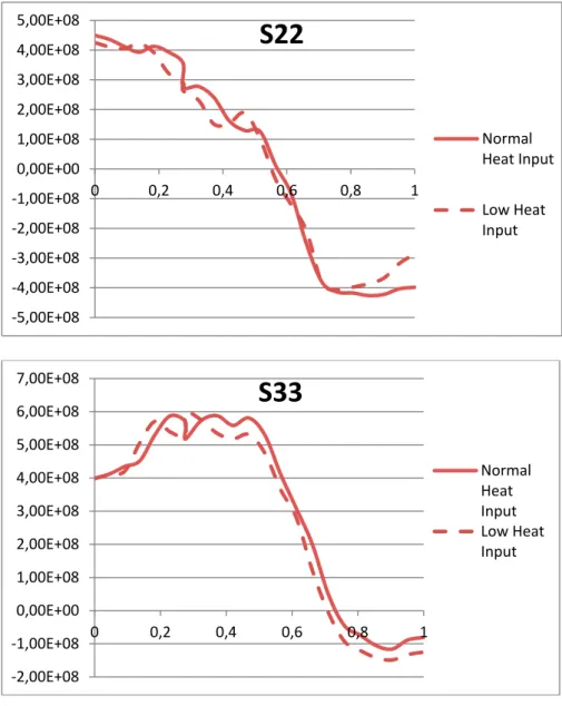
After welding After repair6.2 Inside repair - heat input sensitivity
(t = 12.7 mm)
A sensitivity study with respect to the heat input is performed. The thin pipe case was selected since this weld was sensitive to transition from a linear to sinusoidal stress profile through the thickness. The effect of low heat input is investigated since it was judged that only lower heat input may alter the stress profile. The inside repairs (inlay welds) are performed using GTAW. The case denoted normal corresponds to heat input of 0.56 kJ/mm, and the case low corresponds to heat input of 0.32 kJ/mm. Figure 6.4 show that the stress distributions are only slightly altered, for both axial and hoop stress.
Fig. 6.4: Sensitivity to heat input for inside repair, axial (S22) and hoop (S33) stresses, t = 12.7 mm. Distance is normalized by the thickness and stress values are in Pa.
-5,00E+08 -4,00E+08 -3,00E+08 -2,00E+08 -1,00E+08 0,00E+00 1,00E+08 2,00E+08 3,00E+08 4,00E+08 5,00E+08 0 0,2 0,4 0,6 0,8 1
S22
Normal Heat Input Low Heat Input -2,00E+08 -1,00E+08 0,00E+00 1,00E+08 2,00E+08 3,00E+08 4,00E+08 5,00E+08 6,00E+08 7,00E+08 0 0,2 0,4 0,6 0,8 1S33
Normal Heat Input Low Heat Input6.3 Inside repair - repair thickness sensitivity
(t = 40.5 mm)
The sensitivity of the stress field with respect to the thickness of the inside repair layer is examined. The thick pipe is analysed for an inside repair having a depth corresponding to one more layer of beads, in total four layers. Figure 6.5 shows that the stress distribution is only slightly altered, corresponding to the increased thickness of the repair.
Fig. 6.5: Sensitivity to thickness of the inside repair, axial (S22) and hoop (S33) stresses, t = 40.5 mm. Distance is normalized by the thickness and stress values are in Pa.
-4,00E+08 -3,00E+08 -2,00E+08 -1,00E+08 0,00E+00 1,00E+08 2,00E+08 3,00E+08 4,00E+08 5,00E+08 0 0,2 0,4 0,6 0,8 1
S22
Standard repair Thicker repair -3,00E+08 -2,00E+08 -1,00E+08 0,00E+00 1,00E+08 2,00E+08 3,00E+08 4,00E+08 5,00E+08 6,00E+08 7,00E+08 0 0,2 0,4 0,6 0,8 1S33
Standard repair Thicker repair6.4 Outside repair results
Figures 6.6 and 6.7 show the results for outside weld repairs in DMWs of thickness 12.7 mm and 40.5 mm. The outside repairs results in negligible changes of the stress distributions, for both thicknesses. Figure 6.8 exemplify the increase in plastic strain at the inside surface for a deep repair. Figures A12 and A14 in the Appendix B also show the plastic strain. For these deep outside repairs the plastic strain increase by about 20% in the material remaining at the inside surface, especially at the heat affected zone. This indicate that complete
removal of previous weld and heat affected material can be beneficial.
Fig. 6.6: Deep outside repair; axial (S22) and hoop (S33) stresses for
t=12.7 mm. Distance is normalized by the thickness and
stress values are in Pa.
-2,50E+08 -2,00E+08 -1,50E+08 -1,00E+08 -5,00E+07 0,00E+00 5,00E+07 1,00E+08 1,50E+08 2,00E+08 0 0,2 0,4 0,6 0,8 1
S22
After welding After repair 0,00E+00 1,00E+08 2,00E+08 3,00E+08 4,00E+08 5,00E+08 6,00E+08 0 0,2 0,4 0,6 0,8 1S33
After welding After repairFig. 6.7: Deep outside repair; axial (S22) and hoop (S33) stresses for
t=40.5 mm. Distance is normalized by the thickness and
stress values are in Pa. -5,00E+08 -4,00E+08 -3,00E+08 -2,00E+08 -1,00E+08 0,00E+00 1,00E+08 2,00E+08 3,00E+08 4,00E+08 5,00E+08 0 0,2 0,4 0,6 0,8 1
S22
After welding After repair -3,00E+08 -2,00E+08 -1,00E+08 0,00E+00 1,00E+08 2,00E+08 3,00E+08 4,00E+08 5,00E+08 6,00E+08 7,00E+08 0 0,2 0,4 0,6 0,8 1S33
After welding After repairFig. 6.8a: Outside repair, depth 80%, t=12.7 mm; plastic strain before repair (to the left) and after a repair to 80% depth (right).
Fig. 6.8b: Outside repair, depth 80%, t=40.5 mm; plastic strain before repair (left) and after a repair to 80% depth (right).
6.5 Outside repair - offset sensitivity
(t = 40.5 mm)
The sensitivity with respect to the axial position of the outside repair is examined. The thick pipe is analysed for two outside repairs, see Fig. 6.9, one corresponding to removal of central defect and one for a side defect. Figure 6.10 shows that the stress distribution is only slightly altered.
Fig. 6.9: (a) Cross section of weld repaired for a defect at the fusion line, and (b) sketches of outside weld repairs of a central defect and a side defect.
Fig. 6.10: Deep outside repair offset from weld centre line, t=40.5 mm; axial (S22) and hoop (S33) stresses. Distance is normalized by the thickness and stress values are in Pa.
-5,00E+08 -4,00E+08 -3,00E+08 -2,00E+08 -1,00E+08 0,00E+00 1,00E+08 2,00E+08 3,00E+08 4,00E+08 5,00E+08 0 0,2 0,4 0,6 0,8 1
S22
After repair - no offset After repair - with offset -3,00E+08 -2,00E+08 -1,00E+08 0,00E+00 1,00E+08 2,00E+08 3,00E+08 4,00E+08 5,00E+08 6,00E+08 7,00E+08 0 0,5 1S33
After repair - no offset After repair - with offset7 Conclusions
This project investigates the effects of repair welding in nickel base dissimilar metal welds. The scope of the project cover different types of repairs, e.g. repair at manufacturing, in-service repairs, preventive repairs and outside and inside repairs. The causes to different types of weld repairs and their respective position and configuration are summarised. The effect on weld residual stress and plastic strain are investigated by numerical simulation for selected weld repairs.
Weld repairs in nozzle-to-piping butt welds are reviewed with respect to different configurations and causes. Repairs at the pipe inside surface may be performed to remove a defect found during in-service inspection, or with the purpose to protect weld material susceptible to stress corrosion cracking. Repairs from the pipe outside surface are performed when removing welding defects found during manufacturing. Inside weld repairs are not performed during manufacturing, except for very large diameter piping.
The effect from different weld repairs on the residual stress profile are studied for dissimilar metal welds. Long repairs at the inside and outside surface are studied for different pipe geometries and existing weld residual stresses prior to the repair. The influence of pipe wall thickness, heat input, repair depth and repair position are investigated. The results show that the inside repairs generate high tensile stresses at the inside surface. This is generally unfavourable since stress corrosion cracking would be prevented if stresses at the surface were compressive. Careful consideration is recommended before
performing inside repairs for prevention, although more resistant weld material is used. A compressive stress state before a repair is a very valuable protection, instead of receiving material at the surface with high plastic strains from welding and high tensile stress after repair. The effect from an inside repair was similar for both the thin and thick pipe cases studied. Sensitivity studies were performed with respect to heat input and repair thickness, and the results show small effects. Repair welding from the pipe outside surface results in small changes
of the residual stress field compared to the unrepaired weld. However, for deep repairs from the outside, the material at the pipe inside surface can be subjected to a significant increase in plastic hardening. Material highly hardened from plastic deformation at welding is
outside repair and the original weld was investigated, and the effect was found to be small.
8 Suggestions for further work
The current investigation focuses on long weld repairs at dissimilar metal welds which were investigated by use of axi-symmetric modelling. Long repairs are of primary importance to understand, as they can provide the driving force for stress corrosion crack growth that can result in long cracks around the circumference. In addition the residual stress field present at a large part of the circumference is likely to influence the margin for guillotine break.
Short repairs are likely to represent less hazard compared to long, but their potential consequences still require to be understood. It is
recommended that an investigation is performed of the local effects at short repairs. In order to assess the importance of differences in the weld residual stresses at short and long repairs, it is suggested to evaluate the effect by fracture mechanical assessment for typical cases. For evaluation of short weld repairs, three dimensional modelling is required both in welding simulation and in fracture mechanical modelling. Local effects will be present at the beginning and end of repairs, and the extent of these localised effects for residual stresses can be evaluated, together with its influence on crack growth and fracture margin. This would clarify for which situations the axi-symmetry assumption can result in under prediction of growth rate and damage tolerance for welds with repairs.
9 References
[1] P. Dong, J.K. Hong, P.J. Bouchard, “Analysis of residual
stresses at weld repairs”, Int. J. Pressure Vessels and Piping, Vol 82, p. 258–269, 2005.
[2] F.H. Ku, et al., “Effectiveness of Excavate and Weld Repair on a Large Diameter Piping Dissimilar Metal Weld by Finite Element Analysis”, Proc. ASME 2012 Pressure Vessels & Piping Conf, PVP2012-78618, 2012
[3] P.J. Bouchard, et.al., “Measurement of the residual stresses in a stainless steel pipe girth weld containing long and short repairs”, Int. J. Pressure Vessels and Piping, Vol 82, p. 299–310, 2005. [4] W. Woo, et al., “Residual stress determination in a dissimilar
weld overlay pipe by neutron diffraction”. Mater Sci Eng, A, Vol 528, p. 8021–7, 2011.
[5] J.N. Walsh, et al, “The Influence of Geometry on Residual Stress Around Repair Welds”, Proc. ASME 2013 Pressure Vessels & Piping Conf, PVP2013-97516, 2013.
[6] C.M. Lin, et al., “Effect of repeated weld-repairs on microstructure, texture, impact properties and corrosion properties of AISI 304L stainless steel”. Engng Failure Analysis, Vol 21, p 9–20, 2012.
[7] D. Rudland, et al, “Further Welding Residual Stress and Flaw Tolerance Assessment of Dissimilar Metal Welds with Alloy 52 Inlays”, Proc. ASME 2010 Pressure Vessels & Piping Conf, PVP2010-25433, pp. 1351-1361, 2010.
[8] E. Bonnaud, D. Bremberg, J. Gunnars, "Recommended residual stress profiles for nickel base dissimilar metal pipe welds", Inspecta Report No. 50014970-1, Rev.1, 2015. (to appear as a
SSM research report 2017, dnr SSM2012-1079)
[9] W. Zang, J. Gunnars, P. Dong, and J.K. Hong, "Improvement and validation of weld residual stress modelling procedure, SSM research report 2009:15," ISSN-2000-0456, 2009.
[11] M. Kerr and H. J. Rathbun, “Summary of Finite Element Sensitivity Studies Conducted in Support of the NRC/EPRI Welding Residual Stress Program”, Proc. ASME 2012 Pressure Vessels & Piping Conf, PVP2012-78883, 2012.
[12] J. Mullins and J. Gunnars, "Validation of Weld Residual Stress Modeling in the NRC International Round Robin," Swedish Radiation Safety Authority, SSM Report 2013:01.
[13] S. Hirano, K. Hamasaki1, and K.Okimura, “Maintenance Activities for Alloy 600 in PWR Plants, Part 1-3”, E-Journal of Advanced Maintenance, EJAM Vol.2 No2-4, G13-15, 2010. [14] “Forsmark 3-System 312/321/323, Reparation av
anslutningssvetsar”, Dok. nr: F-P99-004, Rev. 01, Forsmarks Kraftgrupp, 2000.
[15] Welding plan, No: FOR101; Plant: KKW Forsmark, Job-No: 61-2597, Babcock Borsig Power; 2001.
[16] Welding plan, No: FOR102; Plant: KKW Forsmark, Job-No: 61-2597, Babcock Borsig Power; 2001.
[17] Drawing, Forsmark 3, Repair Weld (Cladding), Nozzle at 45º in System 312; Siemens AG; Dept. NDA4, UNID 8651976; Rev. e, 2000.
[18] Drawing, Forsmark 3, Repair Weld (Cladding) Nozzle at 45º in System 323; Siemens AG; Dept. NDA4, UNID 8651969; Rev. d, 2000.
[19] Drawing, Forsmark 3, Repair Weld (Cladding) Nozzle at 135º in System 321; Siemens AG; Dept. NDA4, UNID 8652386; Rev. c, 2000.
[20] Discussion with welding experts at Inspecta; Peter Kihlmark, Sofia Eliasson, Bradley Giordano and Henrik Svensson, January 2016.
Appendix A – Material properties
In the modeling the following properties are needed as a function of temperature; thermal conductivity, density, specific heat capacity, latent heat, thermal expansion coefficient. The thermal material properties used for the nickel based alloys are based upon data
recently published by the NRC [A1]. The thermal properties are from testing of Alloy 82, but are very similar for the nickel based alloys Alloy 600/182/82. Thermal properties for the austenitic stainless steels used in this calculation were also based upon the data published by the NRC from testing of TP316. Thermal properties for the ferritic steel ASTM A-533B were based on the data published in [A2]. The thermal properties are summarized in Table A1-A3.
Table A1. Thermal and physical properties as a function of
temperature for Alloy 182.
Density 8470 kg/m3. Latent heat at melting temperature 297 600 J/kg.
Table A2. Thermal and physical properties as a function of
temperature for austenitic stainless steel 316. Temperature
[oC] Conductivity [W/m oC] Specific heat [J/kg oC] expansion Thermal
[10-6 1/oC] 20 14.2 444 13.9 200 17.2 486 14.3 400 20.0 519 14.8 600 23.5 578 15.7 800 27.3 611 16.6 1000 30.5 630 17.3 1200 34.9 660 19.8 1400 38.0 713 20.2 Temperature
[oC] Conductivity [W/m oC] Specific heat [J/kg oC] expansion Thermal
[10-6 1/oC] 20 13.3 451 15.4 200 16.4 514 16.5 400 19.9 550 17.6 600 22.4 578 18.2 800 25.3 582 18.8 1000 28.1 599 19.4 1200 30.9 610 19.9 1400 33.8 620 20.5
Table A3. Thermal and physical properties as a function of
temperature for ferritic steel A 533B.
Density 7900 kg/m3.
The temperature dependent mechanical material properties used in the calculations are specified based upon data from references [A1-A8]. Note that to avoid non-conservative estimates of the residual stresses, it is important to use typical values for the yield properties. Cyclic tensile data for relevant strain amplitudes and temperatures are generally lacking for these materials, and isotropic hardening models are specified following recommendations in the investigations [A9-A11] for multi-bead welds. Material annealing was simulated at high temperatures. The mechanical properties used are summarized in Table A4 – A6.
Table A4. Mechanical properties as a function of temperature for
Alloy 182. Temperature
[oC] modulus Young's
[GPa]
Poisson's ratio
[-] Yield stress [MPa]
20 214 0.29 311 200 203 0.33 282 400 192 0.35 204 600 180 0.36 163 800 164 0.38 134 1000 143 0.40 71 1200 92 0.40 54 1400 0.1 0.40 35 Temperature
[oC] Conductivity [W/m oC] Specific heat [J/kg oC] expansion Thermal
[10-6 1/oC] 20 43.4 460 12.3 200 40.9 527 13.1 400 38.3 614 14.4 600 34.8 775 14.8 800 36.7 890 11.6 1000 28.3 625 12.5 1200 30.9 694 14.1 1400 33.7 770 -
Table A5. Mechanical properties as a function of temperature for
stainless steel 316.
Temperature [oC] Young's
modulus [GPa] Poisson's ratio [-] Yield stress [MPa] 20 195 0.27 255 200 183 0.28 171 400 169 0.29 153 600 152 0.31 141 800 132 0.31 128 1000 100 0.31 54 1200 57 0.31 26 1400 1 - 10
Table A6. Mechanical properties as a function of temperature for A
533B.
Temperature
[oC] modulus [GPa] Young's Poisson's ratio [-] Yield stress [MPa]
20 200 0.29 459 200 189 0.29 349 400 169 0.30 345 600 122 0.31 151 800 66 0.34 50 1000 36 0.38 20 1200 17 0.38 3 1400 2 - - References Appendix A
[A1] International Weld Residual Stress Round Robin Problem
Statement, Vers 1.0, Office of Nuclear Regualtory Research,
Div. Engineering, Component Integrity Branch, US NRC, 2009. [A2] Review and Analysis of the Davis-Besse March 2002 Reactor
Pressure Vessel Head Wastage Event" Appendix A, Finite
Element Stress Analysis of Davis-Besse CRDM Nozzle 3 Penetration. ML070860281, 2007-03-15.
[A3] The Battelle Integrity of Nuclear Piping (BINP) Program Final
Report, NUREG/CR-6837, Vol. 2, US Nuclear Regulatory
Commission, 2005.
[A5] Rempe, J.L. et al., High Temperature Thermal and Structural
Material Properties for Metals used in LWR Vessels,
Proceedings of ICAPP 2008, Paper 8220, 2008.
[A6] Lindgren, L., Domkin, K., Hansson, S., Dislocations, vacancies
and solute diffusion in physical based plasticity model for AISI 316L, Mechanics of Materials, Vol 40, pp 907-919, 2008.
[A7] Hong, S-G et al, Temperature effect on the low-cycle fatigue
behavior of type 316L stainless steel: cyclic non-stabilization and an invariable fatigue parameter, Mat Sci Eng A, Vol 457,
pp139-147, 2007.
[A8] Reddy, G.B., Ayres, D.J., High-Temperature Elastic-Plastic and
Creep Properties for SA-533 Grade B Class 1 and SA508 Materials, EPRI-NP-2763 Research Project Report, 1982.
[A9] Zang, W., Gunnars, J, Dong, P., Hong, J.K., Improvement and
validation of weld residual stress modelling procedure, SSM
research report, 2009:15, ISSN-2000-0456, 2009.
[A10] Mullins, J., Gunnars, J. Influence of hardening model on
weld residual stress distribution, SSM research report, 2009:16,
ISSN 2000-0456.
[A11] Mullins, J., Gunnars, J. Welding simulation:
Relationship between welding geometry and determination of hardening model, PVP2012-78599, Proc. ASME Pressure
Appendix B - Results
Field plots of axial and hoop stresses as well as effective plastic strain are presented in this appendix for analysed cases. In order to simplify comparisons, the whole set of results are presented, including the path presented in the main section of the report. All results are at room temperature.
Weld repair results - Field plots:
For each repair weld (3 inside repairs and 2 outside repairs), axial stresses (S22), hoop stresses (S33) and effective plastic strains (PEEQ) are presented both before and after repair (Figs. A2, A4, A6, A12, A14). Pictures on the left correspond to the state before repair and pictures on the right, to the state after repair.
Weld repair results – Path plots:
For each repair weld, axial stresses (S22) and hoop stress (S33) are presented along the central line path, both before and after repair. (Figs. A3, A5, A7, A13, A15). The path location is illustrated by the red arrows in Fig. A1.
Fig. A1: Definition of weld centre line path for (a) original weld before repair, (b) after inside repair and (c) after outside repair. Sensitivity studies - Field plots:
For each sensitivity study (two for inside repairs and one for outside repair), axial stresses (S22), hoop stresses (S33) and effective plastic strains (PEEQ) are presented for the different repair alternatives (Figs. A8, A10, A16). Figures on the left correspond to the standard case and figures on the right, to the special case.
Sensitivity studies – Path plots:
For each repair, axial stresses (S22) and hoop stress (S33) are also presented along the same central line path, both for the baseline case and for the alternative (Figs. A9, A11, A17).
A.1 Inside repair: t = 12.7 mm
Fig. A2: Inside repair. Axial stress, hoop stress, effective plastic strain before and after repair, t = 12.7 mm. Stress values are in Pa.
Fig. A3: Inside repair. Axial stress and hoop stress, before and after repair, t = 12.7 mm. Distance is normalized by the thickness and stress values are in Pa.
-5,00E+08 -4,00E+08 -3,00E+08 -2,00E+08 -1,00E+08 0,00E+00 1,00E+08 2,00E+08 3,00E+08 4,00E+08 5,00E+08 0 0,2 0,4 0,6 0,8 1
S22
After welding After repair -2,00E+08 -1,00E+08 0,00E+00 1,00E+08 2,00E+08 3,00E+08 4,00E+08 5,00E+08 6,00E+08 7,00E+08 0 0,2 0,4 0,6 0,8 1S33
After welding After repairA.2 Inside repair: t = 25.5 mm
Fig. A4: Inside repair. Axial stress, hoop stress, effective plastic strain before and after repair, t = 25.5 mm. Stress values are in Pa.
Fig. A5: Inside repair. Axial stress and hoop stress, before and after repair, t = 25.5 mm. Distance is normalized by the thickness and stress values are in Pa.
-4,00E+08 -3,00E+08 -2,00E+08 -1,00E+08 0,00E+00 1,00E+08 2,00E+08 3,00E+08 4,00E+08 5,00E+08 0 0,2 0,4 0,6 0,8 1
S22
After welding After repair 0,00E+00 1,00E+08 2,00E+08 3,00E+08 4,00E+08 5,00E+08 6,00E+08 7,00E+08 0 0,2 0,4 0,6 0,8 1S33
After welding After repairA.3 Inside repair: t = 40.5 mm
Fig. A6: Inside repair. Axial stress, hoop stress, effective plastic strain before and after repair, t = 40.5 mm. Stress values are in Pa.
Fig. A7: Inside repair. Axial stress and hoop stress, before and after repair, t = 40.5 mm. Distance is normalized by the thickness and stress values are in Pa.
-4,00E+08 -3,00E+08 -2,00E+08 -1,00E+08 0,00E+00 1,00E+08 2,00E+08 3,00E+08 4,00E+08 5,00E+08 0 0,2 0,4 0,6 0,8 1
S22
After welding After repair -3,00E+08 -2,00E+08 -1,00E+08 0,00E+00 1,00E+08 2,00E+08 3,00E+08 4,00E+08 5,00E+08 6,00E+08 7,00E+08 0 0,2 0,4 0,6 0,8 1S33
After welding After repairA.4 Sensitivity study: heat input (t = 12.7 mm)
Fig. A8: Inside repair, sensitivity to heat input
.
Axial stress, hoop stress, effective plastic strain before and after repair, t = 12.7 mm. Stress values are in Pa.Fig. A9: Inside repair, sensitivity to heat input
.
Axial stress and hoop stress, before and after repair, t = 12.7 mm. Distance is normalized by the thickness and stress values are in Pa.-5,00E+08 -4,00E+08 -3,00E+08 -2,00E+08 -1,00E+08 0,00E+00 1,00E+08 2,00E+08 3,00E+08 4,00E+08 5,00E+08 0 0,2 0,4 0,6 0,8 1
S22
Normal Heat Input Low Heat Input -2,00E+08 -1,00E+08 0,00E+00 1,00E+08 2,00E+08 3,00E+08 4,00E+08 5,00E+08 6,00E+08 7,00E+08 0 0,2 0,4 0,6 0,8 1S33
Normal Heat Input Low Heat InputA.5 Sensitivity study: repair thickness (t = 40.5 mm)
Fig. A10: Inside repair, sensitivity to repair thickness
.
Axial stress, hoop stress, effective plastic strain before and after repair,Fig. A11: Inside repair, sensitivity to repair thickness
.
Axial stress and hoop stress, before and after repair, t = 40.5 mm. Distance isnormalized by the thickness and stress values are in Pa.
-4,00E+08 -3,00E+08 -2,00E+08 -1,00E+08 0,00E+00 1,00E+08 2,00E+08 3,00E+08 4,00E+08 5,00E+08 0 0,2 0,4 0,6 0,8 1
S22
Standard repair Thicker repair -3,00E+08 -2,00E+08 -1,00E+08 0,00E+00 1,00E+08 2,00E+08 3,00E+08 4,00E+08 5,00E+08 6,00E+08 7,00E+08 0 0,2 0,4 0,6 0,8 1S33
Standard repair Thicker repairA.6 Deep outside repair: t = 12.7 mm
Fig. A12: Outside repair. Axial stress, hoop stress, effective plastic strain before and after repair, t = 12.7 mm. Stress values are in Pa.
Fig. A13: Outside repair. Axial stress and hoop stress, before and after repair, t = 12.7 mm. Distance is normalized by the thickness and stress values are in Pa.
-2,50E+08 -2,00E+08 -1,50E+08 -1,00E+08 -5,00E+07 0,00E+00 5,00E+07 1,00E+08 1,50E+08 2,00E+08 0 0,2 0,4 0,6 0,8 1
S22
After welding After repair 0,00E+00 1,00E+08 2,00E+08 3,00E+08 4,00E+08 5,00E+08 6,00E+08 0 0,2 0,4 0,6 0,8 1S33
After welding After repairA.7 Deep outside repair: t = 40.5 mm
Fig. A14: Outside repair. Axial stress, hoop stress, effective plastic strain before and after repair, t = 40.5 mm. Stress values are in Pa.
Fig. A15: Outside repair. Axial stress and hoop stress, before and after repair, t = 40.5 mm. Distance is normalized by the thickness and stress values are in Pa.
-5,00E+08 -4,00E+08 -3,00E+08 -2,00E+08 -1,00E+08 0,00E+00 1,00E+08 2,00E+08 3,00E+08 4,00E+08 5,00E+08 0 0,2 0,4 0,6 0,8 1
S22
After welding After repair -3,00E+08 -2,00E+08 -1,00E+08 0,00E+00 1,00E+08 2,00E+08 3,00E+08 4,00E+08 5,00E+08 6,00E+08 7,00E+08 0 0,2 0,4 0,6 0,8 1S33
After welding After repairA.8 Sensitivity study: location of outside repair
Fig. A16: Outside repair, sensitivity to repair position. Axial stress, hoop stress, effective plastic strain before and after repair, t = 40.5 mm. Stress values are in Pa.
Fig. A17: Outside repair, sensitivity to repair position. Axial stress and hoop stress, before and after repair, t = 40.5 mm. Distance is normalized by the thickness and stress values are in Pa.
-5,00E+08 -4,00E+08 -3,00E+08 -2,00E+08 -1,00E+08 0,00E+00 1,00E+08 2,00E+08 3,00E+08 4,00E+08 5,00E+08 0 0,2 0,4 0,6 0,8 1
S22
After repair -no offset After repair -with offset -3,00E+08 -2,00E+08 -1,00E+08 0,00E+00 1,00E+08 2,00E+08 3,00E+08 4,00E+08 5,00E+08 6,00E+08 7,00E+08 0 0,2 0,4 0,6 0,8 1S33
After repair -no offset After repair -with offset2017:22 The Swedish Radiation Safety Authority has a comprehensive responsibility to ensure that society is safe from the effects of radiation. The Authority works to achieve radiation safety in a number of areas: nuclear power, medical care as well as commercial products and services. The Authority also works to achieve protection from natural radiation and to increase the level of radiation safety internationally.
The Swedish Radiation Safety Authority works proactively and preventively to protect people and the environment from the harmful effects of radiation, now and in the future. The Authority issues regulations and supervises compliance, while also supporting research, providing training and information, and issuing advice. Often, activities involving radiation require licences issued by the Authority. The Swedish Radiation Safety Authority maintains emergency preparedness around the clock with the aim of limiting the aftermath of radiation accidents and the unintentional spreading of radioactive substances. The Authority participates in international co-operation in order to promote radiation safety and finances projects aiming to raise the level of radiation safety in certain Eastern European countries.
The Authority reports to the Ministry of the Environment and has around 300 employees with competencies in the fields of engineering, natural and behavioural sciences, law, economics and communications. We have received quality, environmental and working environment certification.