AIR AND WATER REQUIREMENTS
FOR- FOAM DRILLING OPERATIONS
By
ProQuest N um ber: 10781730
All rights reserved INFORMATION TO ALL USERS
The q u a lity of this re p ro d u c tio n is d e p e n d e n t u p o n the q u a lity of the c o p y s u b m itte d . In the unlikely e v e n t that the a u th o r did not send a c o m p le te m a n u s c rip t and there are missing p a g e s , these will be n o te d . Also, if m a te ria l had to be re m o v e d ,
a n o te will in d ic a te the d e le tio n .
uest
P roQ uest 10781730
Published by ProQuest LLC(2018). C o p y rig h t of the Dissertation is held by the A u tho r.
All rights reserved.
This work is p ro te c te d a g a in s t u n a u th o riz e d c o p y in g under Title 17, United States C o d e M icro fo rm Edition © ProQuest LLC.
ProQuest LLC.
789 East Eisenhower Parkway P.O. Box 1346
SUBMITTAL
A Thesis submitted to the Faculty-and the Beard of Trustees of the Colorado School of Mines in partial fulfillment of the r e quirements for the degree of Masters of Science, Petroleum
Engineering. Signed:_______ 4^'Student G o lden , Colorado Date :Q ( e 'i&tldJj/f, 19 *7/ « t Q n A D O S C H O O L O F m q u -’O L D E N , C O L O R A D O G o lde n, Colorado J L : 19, 7 1 Approved . Thesis/ Advisor A o d - / Head of Department
T-1383
ABSTRACT
This study investigates a mathematical-model and its solution for the application of foam in a drilling system consisting cf a vertical- concentric pipe-hole arrangement with flow down the pipe and up the a nnulus. The mathematical model which was written for foam was the Bingham plastic model (Mitchell, 1970b) applied to a compressible fluid, Foam-consisting of air, a surface active agent, and water, with the aqueous solution being the continuous phase and the air being discon tinuous bubbles, shall be considered. Two equations were written de scribing the flow of foam: foam flowing down the pipe, and foam with rock chips flowing up the annulus. ^ I n order to maintain nearly constant fluid properties, the two equations were written - explicitly in terms of pressure and depth and solved by iterations with a constant pressure in crement. For each iteration, the Theological properties of foam were evaluated at the average increment pressure. Adjustments to account for the rock chips volume and mass were made to the annular Bingham plastic flow, equation,
Air volume rate, water volume rate, and surface annular pressure are the variables in the drilling system. Surface injection pressure, drilling rate, hole size, and pipe size were kept constant for each solution. Boundary conditions of foam flow of 1.5 fps at the bottom of the annulus and a quality (ratio of air volume to water plus air volume) of 0.96 at the surface of the annulus were imposed upon the solution of the mathematical model, With these boundary conditions,
the air and water volume rates, and surface annular pressure were calculated using a high-speed digital computer. Solutions for various hole and pipe combinations, drilling rates, and surface injection pressures are listed in tabular form at the end of this paper.
T-1383
ACKNOWLEDGMENTS
The author wishes to express his gratitude to Dr. B. J. Mitchell for suggesting this investigation, for giving valuable guidance and helpful assistance, and for serving on this thesis committee.
Many thanks are due to Dr. R. R. Faddick and C. A. Kohlhaas for serving on this thesis committee and their valuable help.
TABLE OF CONTENTS
Page
Abstract iii
Acknowledgements v
List of Tables vii
List of Figures ix
I Introduction 1
II Review of Foam Rheology *4
III Method of Investigation 11
IV Results 25
V Discussion of Results 30
VI Conclusions and Recommendations 32
Appendices
Appendix A Nomenclature 79
B Bingham Plastic Model Flow Down
the Pipe 81
C Bingham Plastic Model Flew Up
the Annulus 37
D Computer Program Listing 90
T-1383
LIST OF TABLES
Table Page
1. Shear Stress-Shear Rate Relationships For
Drilling Foam 5
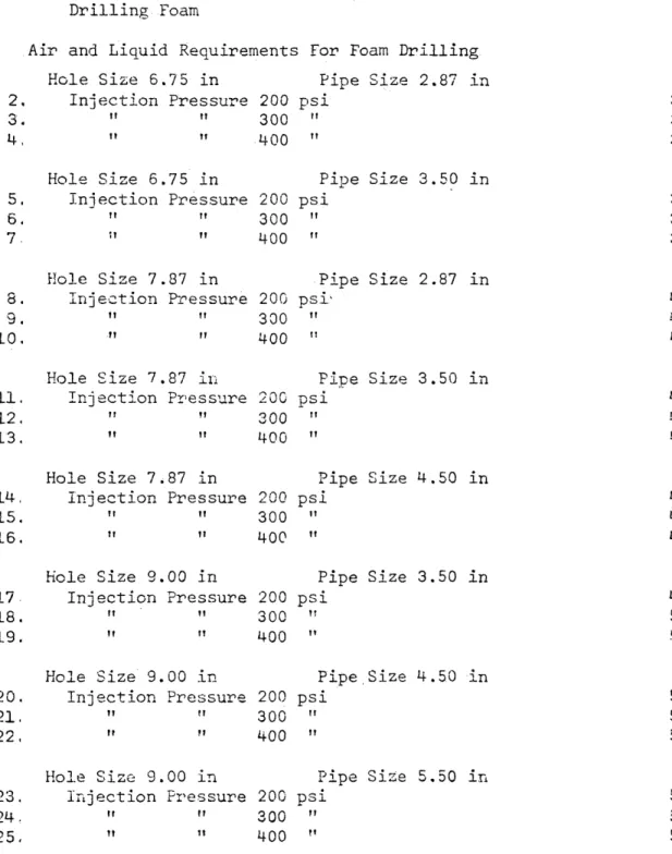
Air and Liquid Requirements For Foam Drilling Hole Size 6.75 in Pipe Size 2.87 in
2. Injection Pressure 200 psi 34
3. " " 300 " 35
4. " " 400 " 36
Hole Size 6.75 in Pipe Size 3.50 in
5. Injection Pressure 200 psi 37
6 . ~ " " 300 " 38
7. n " 400 " 3Q
Hole Size 7.87 in Pipe Size 2.87 in
8 . Injection Pressure 200 psi' 40
9. " " 300 ‘ " 41
10. " ” 400 " 42
Hole Size 7.87 in Pipe Size 3.50 in
11. Injection Pressure 200 psi 43
12. " ” 300 M 44
13. " " 400 " 45
Hole Size 7.87 in Pipe Size 4.50 in
14. Injection Pressure 200 psi 46
15. " M 300 M 47
16. " " 400 " 48
Hole Size 9.00 in Pipe Size 3.50 in
17 Injection Pressure 200 psi 49
18. " " 300 " 50
19. " " 400 " 51
Hole Size 9.00 in Pipe,Size 4.50 in
20. Injection Pressure 200 psi 52
21. " " 300 ” 53
22. " ■' 400 M 54
Hole Size 9.00 in Pipe Size 5,50 in
23. Injection Pressure 200 psi 55
24. " " 300 " 56
25. n ” 400 M 57
Table 26. 27. 28. 29. 30. 31. 32. 33. 35. 36. 37; 38. 39. 40. 41 42. 43. 44, 45, 46, LIST OF TABLES Page Hole Size 9.87 in Pipe Size 3.50 in
Injection Pressure 200 psi 58
” " 300 " 59
" » 400 ” 60
Hole Size 9.87 in Pipe Size 4.50 in
Injection Pressure 200 psi 61
" ” 300 " 62
” " 400 ?r 63
Hole Size 9.87 in Pipe Size 5.50 in
Injection Pressure 200 psi 64
" » 300 11 65
" " 400 " 66
Hole Size 12.50 in Pipe Size 4.50 in
Injection Pressure 200 psi 67
" ” 300 " 58
" " 400 " 69
Hole Size 12.50 in ripe Size 5.50 in
Injection Pressure 200 psi 70
n it 300 71
ft i-QO " 72
Hole Size 15.00 in Pipe Size 4.50 in
Injection Pressure 200 psi 73
m m 300 •' 74
” " 400 M 75
Hole Size 15.00 in Pipe Size 5.50 in
Injection Pressure 200 psi 76
" » 300 " 77
T-1383
LIST OF FIGURES
Figure Page
1. Schematic Diagram of Idealized Foam System 3
2. Yield Stress vs. Foam Quality, 7
3. Plastic Viscosity vs. Foam Quality 8
4. Foam System in Down Pipe 10
5. Forces Acting on Downward Flow In a Pipe 12 6 . Air and Liquid Requirements For Foam Drilling
Hole Size 9.00 in Pipe Size ^.SO in
Injection Pressure 200 psi 25
7. Air and Liquid Requirements For Foam Drilling Hole Size 9.00 in Pipe Size 5.50 in
Injection Pressure 200 psi 27
8 . Flow Of a Bingham Fluid In a Circular Tube 82 9. Rectilinear Flow Between Fixed Parallel Plates 88
CHAPTER ONE INTRODUCTION
The use of foam in drilling operations in the petroleum industry dates back to the early trials of air drilling during the late lOM-O's.
(P. Moore, 1966, p. lM-A). Foam was used in air drilling as a means of stabilizing a sloughing formation and controlling natural water flows in the w e l l b o r e during drilling operations. If air.were used to drill an unconsolidated formation, the hole would usually cave. When a water producing formation was drilled with air, the wetted cuttings often stuck to the drillpipe and the wall of the hole until circulation was lost and the pipe was packed in the hole. Foam was used to minimise these problems. Foam has proven itself to have an excellent capacity to stabilize a sloughing formation. (Dresser Magcobar, 1970, p. i). Foam, when used in the drilling of a water producing formation, has a tendency to use the water which flows into the wellbore as part of the water constituent of the foam. The cuttings are not wetted by the water and do not stick to the drillpipe or the wall of the hole. At the present time (1971), there is little published literature de scribing the practical application for a foam drilling operation.
In this study, foam consisting of air, a surface active agent, and wafer shall be considered. The surface active agent and the water are the continuous phase with the air appearing as discontin uous bubbles, Mist shall be defined as a fluid consisting of the above components, except the air shall be the continuous phase and
T-1383
the aqueous solution shall appear as droplets.
In the practical application of foam, the following variables must be controlled: 1) air volume, 2) aqueous volume, 3) injection pressure, and 4) annulus choke-pressure,
It is the purpose of this study to (present a mathematical^
model and its solution for the application of foam in a system having the following components: vertical hole, concentric annulus between the hole and the pipe, and continuous circulation of foam down the pipe and up the annulus carrying the wetted cuttings from the bottom of the pipe. (See Figure 1). The solution of the mathematical model was computed by selecting air and aqueous volumes for various pipe and hole configurations. Using an iteration process, the aqueous volume, air volume, and surface annulus pressure have been calculated for a depth range of 1,000 ft, to 4,000 ft., a surface injection pressure of 200 psi to 400 psi, and a drilling rate of 0 fps to 1.5 fps,
Fipe Flow of Foam
Annular Flow of Foam and Cuttings
--D
FI CURS: 1
SCHEMATIC DIAGRAM OF IDEALIZED FOAM SYSTEM
T-1383
CHAPTER TWO REVIEW OF FOAM RHEOLOGY
Mitchell (1970a, p. 117-123) has shown through laboratory
measurements that foam has a linear relationship of shear rate-shear stress for all foam qualities and all shear rates above 20,000 sec ^ For shear rates below 20,000 sec “ , 'the shear rate-shear stress rela tionship is linearized by subtracting the proper constant from the measured shear stress (x). The power law model equation which de scribes the rheology of foam is
(i x ) = M 1
Y P
where x = measured shear stress x = yield shear stress
y
n = power coefficient ii.p_= .plastic viscosity
<p = shear rate The log form of Equation (1) is
log (x -x ) = nlog ($) + log (pi ) 2
y P
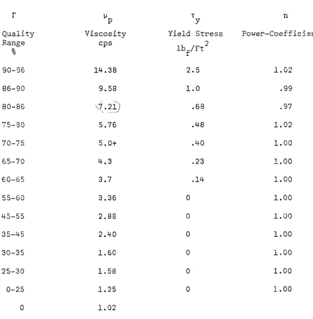
Power coefficients, plastic viscosities, and yield stresses are listed in Table 1 for a foam quality range of 0 to 0.96.
Based upon the data shown in Table 1 , the power coefficient (n) has been chosen to be unity for all foam qualities. Therefore, Equation (1) is equivalent to the shear rate-shear stress relation ship for a Bingham plastic model Figures 2 and 3 show th e: relation ship between foam quality ( D , ratio of air volume to the air volume
TABLE 1: SHEAR STRESS - SHEAR RATE RELATIONSHIPS'FOR DRILLING FOAM (After Mitchell, 1970a)
r
p p
T
y n
Quality Viscosity Yield Stress Power-Coeff:
Range % cps lb./Ft2 r 9 0- 3 6 1 4 . 3 8 2 . 5 1 . 0 2 8 6 - 9 0 9 . 5 8 1 . 0 .99 8 0 - 86 ' 7 . 2 1 ) .68 .97 7 5 - 8 0 5 . 7 6 . 48 1 . 0 2 7 0 - 7 5 5 . 0 + . 40 1 . 0 0 6 5 - 7 0 4 . 3 .23 1 . 0 0 6 0 - 6 5 3 . 7 .14 1.00 5 5 - 6 0 3 . 3 6 0 1 . 0 0 4 5 - 5 5 2 . 8 8 0 1 . 0 0 3 5 - 45 2 . 4 0 0 1 . 0 0 3 0 - 3 5 1 . 6 0 0 1 , 0 0 2 5 - 3 0 1 , 5 8 0 1 . 0 0 0 - 2 5 1 . 2 5 0 1 . 0 0 0 1 . 0 2
The above shear rate shear stress foam data were taken b} Mitchell (1970a) and shown to fit the following equation:
(x - t ) = y <j>n
T-1383
plus water volume , yield stress an<^ plastic viscosity ^4^)-(Mitchell, 1 9 7 0b).
Q u alit y.Regions
Figures 2 and 3 have been divided into three quality regions: dispersed bubble, bubble interference, and bubble deformation. The dispersed bubble region exists for a quality range between 0 and 0.525. Tha_vi.s.cjQjslpy of ^fqam in this region— is— no±-.a function of shear rate. (Mitchell, 1970a, p. 57)
The bubble interference region exists for a quality range be tween 0.525 and 0.74, It is interesting to note that uniform spheres packed loosely (cubically) produce a solids content of 0.52 by volume and when they are tightly packed (rhcmbohedrally) without deformation the concentration is 0.74, The shear stre s s ,,„p 1 as1 1 c v 1 scos.i.ty-,— and yield stress of the foam in thls...regiou..are a_f.unctlon of-shear_.r.ate and foam ..quality-. (Mitchell, 1970a, p. 57).
The bubble deformation region exists for a quality range b e
tween 0.74 and 0.95, All the bubbles in this region are assumed to be deformed. As the quality increases above 0.74, the bubbles cannot expand without deforming the surrounding bubbles. Maximum resistance to flow of foam exists in this region. The shear stress, plastic v i s cosity, and yield stress of the foam in this region are also functions of shear rate and foam dua l i ty .... (.Mi£.cbe.lX.,....1970 a , p. 57), For foam qualities greater than 0.96, mist flow is assumed to exist.
A. o CO oo i-i *H <D PQ O Q O O • • CM rl • w , a o > >■» c *-CM EH ON ►H 00 CO 1.-1— 5 rH < • * Eli} < ft url oz CD I—’ & CKC b> £-< CO a ? (,-j d • s o n jO < M <1 * o p O - p 03 M >* fc« ♦H cm CO -P Q CO w \ H £H Jh s> > * CO pH
S
T-1383
A
v SCO 01 CJ M fx] 3S' « — o 0) *H I—I ^ ,£1 o rO +> 2 S3 oq Hi M M ■O o CO » JH >-< >-• C^\ c.o <*, r~} r=j o < 05 CO £3 D H C ? o > '—ii «£< Si O <i M O E-* 00a
p* ,o o o-On rH 0) o J-3 •H r-t 0 M M 03 E-t o 01 o 3 PU 01 ►—i P-t > O 8Velocity Profile
The velocity profile for flow of foam in a circular pipe is based upon a Bingham model as shown'by-.Figure 4, Three, flow regimes are present: Laminar, transition, and plug. The pipe wall is assumed to be coated with a static, thin layer of the aqueous solution. The shear rate and shear stress have maximum values at the wall of the pipe and minimum values at the axis of the pipe. The flow parallel to the longitudinal axis of the pipe may be represented by concentric element al thin cylinders., Each cylinder has an individual shear rate and shear stress. Laminar flow will exist in those cylinders which have shear rates greater than or equal to about 20,000 sec ^ A transi tional regime separates the laminar and plug flow regimes, The plug regime will include all cylinders having a shear rate equal to zero.
T-1383
Q> N 4 -ci to <D -p tou
a
3 o XJ CO' iH o i f i •H O O Plug 5 * Flow o o o o CM C o P 3 •H -P £Q FIGURE: 4FOAM SYSTEM IK DOWN PIPE
CHAPTER THREE METHOD. OF INVESTIGATION Bingham Plastic Model , „ *
The Bingham plastic model is described by the following assumptions:
1. Isothermal, steady-state flow through a vertical circular pipe.
2. Rate of shear is proportional to the excess of the shear stress over a constant yield value, below which the material behaves as a continuous unit.
3. No slippage exists at the pipe wall,
Using these assumptions the Buckingham-Reiner equation may be developed. (See Figure 5 and Appendix B):
0- V 1 y + 1 - T ^ n _y_ 8y L P 3t r 3 -T r J _ where Q = Volumetric flow rate
L = Flow length R = Pipe radius
t = Shear stress at the pipe wall K
P = P PgL p = Pressure
g = Gravitational constant p = Fluid density
Tn
P A. n 12 R
i) Total Pipe Length
Elements , L0 , •«.., L
1 2 n
are chosen s\ach that Pn-P, = F -P. = ...P ,-P
0 1 1 2 n-1 n
b) Segment of Pipe Length
FIGURE * 5
FORGES ACTING ON DOWNWARD FLOW IN A PIPE
model assumes that the fluid has a constant temperature. However, in a foam drilling application, the fluid temperature will increase with depth. As an approximation to isothermal flow, the pipe and annulus are divided into incremental lengths and the temperature throughout each increment is assumed to be constant and equal to the formation temperature at any depth, A surface temperature of 50°F. and a
o
geothermal gradient of 1 .S"F./100 f t , , as an accepted rule of thumb, have been used to determine the formation temperature for each incre mental depth. No additional temperature correction has been made due to the compression or expansion of the air, or the friction of flow in the pipe or annulus,
A circular pipe and annulus are assumed. No correction has been attempted for an eccentric pipe-annulus arrangement. In actual practice, the drilled hole will not be truly circular and the pipe-annulus
arrangement will not be concentric. Since the severity of eccentricity is not known, the ideal case has been used for computational purposes.
Mitchell (1970a, p. 60) found through laboratory experimenta tion that foam slippage at the pipe wall did not exist or was insig nificant ,
The foam viscosities and yield stresses have only been measured between 71°F* and 31°F (Mitchell, 1970a, p. 37). Temperature
varia-T-1383
tions and its effect on the foam viscosity and yield stress have not been investigated. No attempt has therefore been made to include temperature-viscosity and temperature-yield stress relationships. Numerical Integration Procedure
Flow Down the P i p e : The pressure-depth relationship for the flow o f foam down the pipe is calculated by Eq. (3). The term
q
(Ty/T^) ^-s assumed to be relatively small, and is dropped from Eq. (3), Craft, et al, (1962, p. 38) state that the error is less than 2 per cent whenever tu exceeds 2.5 t . The more convenient anoroximate
R y
expression describing the flow rate of a Bingham plastic fluid is then
Q =
TT R (P„-PT ) 8y L
P LR
The volumetric flow rate (Q) is defined by
r\
Q = tt R^V
where V = Average fluid velocity.
Substituting Eq. (5) into Eq. (4) and solving for Tj, results ii
t R*-(P ~P_)- V 0 L ___ _ R^(Pr-PT ) 8[i LV
0 L- P
The shear stress at the pipe wall (t ; is given by
<WR
‘B 2L
Comparing Eq. (5) and Eq, (7) gives
r
(
p
-p )
r r
r
_ 0 _ L i - il _X_
"
3 J 21. r i p ~p )^ '
uo
V
Sii LV P -J 14and solving for the pipe length (L) results in
9 8i R t 24 Vy
y p
The statis pressure head is also expressed in terms of the pipe length
explicit equation describing the pressure-depth relationship of a Bingham plastic fluid:
In order to apply Eq. (II) to foam, which is a compressible fluid, the pressure dependent variables, -flowing density (p), yield
small constant value of 5 psi and the incremental pipe length will be calculated, Solution of Eq. (11) with constant pressure differentials of 2.5, 5.0, 7 .5, and 10 psi showed that the pressure dependent
variables did not vary significantly for this range. Five psi was therefore used for the calculations, Writing Eq. (11) in an iteration form and summing from the surface to the bottom of the pipe, the total pressure-depth relationship for foam flow down a vertical pipe is determined:
(L) as
P 0 PL p 0 ~ P L + PgL 10
Substituting Eq, (10) into Eq. (9) and solving for L results in an
11
stress (t ), and plastic viscosity (u ), must be maintained at nearly
y p
constant values. The pressure change i p -p ) will be maintained at a
T-1383 12 C T . O V . J J . ^ p>g _ __y±. 3R p 2 i=l
The following discussion explains the evaluation of the second ary variables for each iteration of Eq. (12).
The volume flow rate for water at a depth z, Qw z > i-3 equal to the volume flow rate for water at standard conditions s , Q
ws
Q = Q. 13
wz ws
The volume flow rate for air at a depth z , Q , is determined az
with the ideal gas law. The ideal gas law mathematically expresses F Vol
that the pressure-volume-temperature ratio at state 1 . (— — )., , is
equal to the pressure-volume-temperature ratio at state 2 , ( ^ :
P V o l p Vol
(£_12£) = (s_lE±.)
in.
' rp T 2
where Vol = Volume of gas T = Temperature
If the expansion or compression of a gas from state 1 to state 2 does not fulfill the relationship of Eq. ( I T ) , the gas is considered to be non-ideal, Joule and Thompson have measured the non-ideality of gases (Barrows, 1966, p. 138-140) and expressed it by
/ 3T x 1c
yJT “ 3P H
where y = Joule-Thompson coefficient
U 1
3T
(w7r)u = Change of temperature with respect to a change of
or n
pressure at constant enthalpy
H = Enthalpy
For the expected pressures and temperatures of a drilling operation, the Joule-Thompson, coefficient for air is close to zero. Air will therefore he assumed to behave as an ideal gas and follow the mathe matical relationship of Eq. (14), Hence
Q = Q (P/T) (T/P) 16
az as s z
The total volume flow rate at a depth z, Q , is tz
= Q + Q 17
tz wz az
At a depth z, the mass flow rate of air (M ), water (M ), and
^ az wz
the total (II ) are tz M = Q p \ IS az az^az) M = Q p , 19 W Z ItiZ w z M = M + M 20 tz as wz
The density (p) of flowing foam at a depth z is
pz = % / ( Q t z ) 21
In order to determine the pressure cha.nge attributable to friction, the plastic viscosity, yield str e s s , and velocity must be. kbAHEU. The foam quality at z must first be determined in order to evaluate the yield sjtress,.. and .plastic ,viscps.ify.;„
Foam quality (T) is defined as
r _______ air volume_________ 22
T-1383
The foam quality at z may be found by the following calculation:
r
^
rz a 0 - 23
'tZ
Once the quality is known, the yield stress and plastic -viscosity may be determined from Figures 2 and 3.
The velocity of foam at z is
Qtz z A.
l
where A. = Pine flow area. l
In order to solve Eq. (12) this procedure must be followed: I) the volume flow rate at z for water (Q ), air (Q ), and total
W Z O.Z
( Q ^ ) are calculated with Eas. '(13), (15), and (17): 2) the mass flow rate at z for air (M ), water (M ), and total (M^ ) are
calcu-az 5 wz r tz
latea with E q s . (13), (19), and (20): 3) the foam flowing density (p^)' is calculated with Eq. (21): 4) the quality at z, F , is cal-culatea with Eq. (23): 5) the yield stress at z, Ty Z s and plastic viscosity at z, are evaluated from Figures 2 and 3 -with the use
p z ' -.. - — . •
of the quality at z : 5) the velocity at z, V , is calculated with Eq. (24), All the variables in Eq. (12) are now known and the incre mental length for foam flow down the pipe may be determined for one
iteration.
Flow Up the Annulus: Melrose, et al (1958, p. 315-324) have shown that the flow equation for the isothermal, laminar flow of a Bingham plastic fluid in a concentric pipe-annulus arrangement could
be approximated with good precision by the equation which describes laminar flow through a narrow slot. The flow equation can be written as 9 EW x Q = w 6y ( \ 31 3x T \ i - o 2t 7 + i2 ' J L \x 1 w W / V / -Where E = Lateral extent of the slot
= Mean annular circumference, tt
D + D. o i 25 W = Width of slot = Annular width, ~(D -D.) 2 o l D = Annulus outside diameter
0
D. = Annulus inside diameter 1
t = Shear stress at the slot wall w
For the derivation of Eq. (25), refer to Appendix C.
The pressure-depth relationship for the flow of a Bingham
plastic fluid in a pipe-annulus arrangement is calculated with the use 3
of Eq. (25), The last term in Eq. (25), (t /x ) , is assumed to be
^ ^ y w 5
small and is dropped. Craft, et al. (1962, p. 43) state that the
error is less than 7 per cent whenever x exceeds 2.5 x . The
approxi-w y
mate equation describing the annular flow rate, Q, is
Q = 2 EW x w 6u 3X 1 V 26
The volumetric flow rate, 0, is
T-1.383 Thus V = Wt Sy 1 -3t 2T 28 w
Solving Eq. (28) for the shear stress at the slot wall (t ) w 12Vy
2t +' 3 t
w W y
The shear stress at the slot wall is W(p0-pL )
29
2L 30
Comparing Eq. (29) and Eq. (30) give; W(P -P_) 12Vy
0 L _ p
+ 3t
L W y
and solving for the pipe length (L)
31 L = (Pn-P. ) 0 jj 12Vy OT P y w w 32
The static pressure head, however, is also expressed in terms of the pipe length (L)
L = P 0 pL PgL
The slot width (W) is analogous to the annular width and is given by
W = - A V -D.)
2 o i 34
Substituting Eq. (33) and Eq. (34) into Eq. (32) and solving for L results in an explicit equation describing the pressure-depth rela tionship for the flow of a Bingham plastic fluid up a concentric annulus:
■P-D -■P-D 3t y___ |<D -D.) I O .L + Pg
Eq. (35) is applied to foam, a compressible fluid, by maintain ing the pressure-dependent variables, flowing density (p), yield stress ( ) , and plastic viscosity (y ) nearly constant values. The total pressure difference (p -p ) is maintained again at 5 psi and
U ■“ Li
the incremental annulus length is calculated. Writing Eq. (35) in an iteration form and summing from the bottom of the pipe to the annulus surface, the total pressure-depth relationship for the flow of foam up a concentric annulus is calculated:
n V f Lo / t 2. - . (p.., ‘ 1+1 P-)ci
/
i=l - j' '18V.P . ■J . 1 D1 p g + + r ^ 5t V I ( D - D . d < V V | 36 o iBecause the particles are being lifted by the foam in the annulus, the flowing densit^r, quality, and velocity calculations must be ad justed for the mass and volume of the sand cuttings. A constant drilling or cleaning rate will be assumed.
The density of foam flowing in an annulus at a depth z will become
tz n
(Q
tz, n r
37
where M = Mass rate of rock r
0 = Volume flow rate of rock r
T -1333
The velocity of the foam and rock chips in the annulus is
Qtz + % '
where A = Annular flow area.
Since the calculation.of foam quality requires the knowledge of the air and water volumes, a correction must be made for the rock chip volume in the annulus. Writing a volume balance on a section of the annulus:
Vol + Vol = Vol Vol 39
az wz ann rock
where Vol = Volume of air at z az
Vol = Volume of water at z wz
Vol = Volume of annulus ann
Vol , = Volume of rock rock
The annular volume for a unit length is
7 7
tt ( D -D . )1
Vol = --- 2 * — 40
ann 4
Assuming that rock particle slippage does not occur, then the rock volume flowing in a unit length of annular volume is
(Vol )Q
Vol , = 41
rocK CL + Q 'tz r
Substitution of Eq. (40) and Eq. (41) into Eq. (39( gives the air and water volumes in a unit length of the annulus:
^ Vol + Vol (D2-D2 ) 1 4 - / --- ~— r— \ 42
— -az wz) V o i Qtz +
The volume of air at a depth z in the unit length of the annulus is Q Vol Vol = -^2--- 4.3 aZ Qtz + r The quality at z is Vol v/. = --- -2iE— — z) Vol + Vol az wzy
In order to solve Eq, (36) this procedure must be followed: 1) the density, p^, of flowing foam at z is calculated with Eq, (37): 2) the velocity in the annulus, V' , is calculated with Eq. (38): 3)
z
in order to evaluate the quality, T , at z, E a s . (42) and (43) must be solved and substituted into Eq. (44): 4) the yield stress at z,
an<3 plastic viscosity at z, y , are evaluated from Figures 2 and 3 with the use of the quality at z. All the variables in Eq. (36) are now known and the incremental length for fcarn flow up the annulus may be determined for one iteration.
Two differential equations result from the mathematical model describing the flow of foam in a drilling operation: one for the pipe flow and one for the annular flow. The differential equations are explicitly expressed in terms of pressure and depth and are numerically integrated over the full length of the pipe with a constant pressure increment. An iteration process develops because at the bottom of the pipe the pressure within the pipe must equal the pressure within the annulus. Further boundary conditions are: 1) a minimum annular velocity at the bottom of the pipe: 2) a maximum foam quality at the
T-1383
surface in the annulus. At the bottom of the pipe, foam velocity will be the controlling quantity for removal of cuttings. The foam velocity must be kept at a minimal value in order to reduce the enlargement of the hole. Foam quality should be a maximum at the annulus surface.
The viscosity- of foam does reach a maximum value at the beginning of the mist region. (See Figure 3). If the quality is allowed to enter the mist region, the viscosity will approach that of air, This annular boundary condition at the surface will therefore control the maximum quality which is desirable for the most efficient cutting removal.
In order to maintain good hole properties, a bottom-hole annular velocity of 1.5 fps (Wolke, 1970), and a foam quality of 0.96 in the annulus at the surface will be imposed upon the system as boundary conditions. Field experience indicates that a bottom-hole velocity of 1.5 fps will clean the hole of all solid particles while using foam. If the quality becomes greater than 0.96, the foam viscosity will
decrease to that of mist and the solid particles will perhaps not be carried from the annulus, With the stipulated boundary conditions, the required air volume, aqueous volume, and the annulus choke- pressure are determined.
CHAPTER FOUR RESULTS
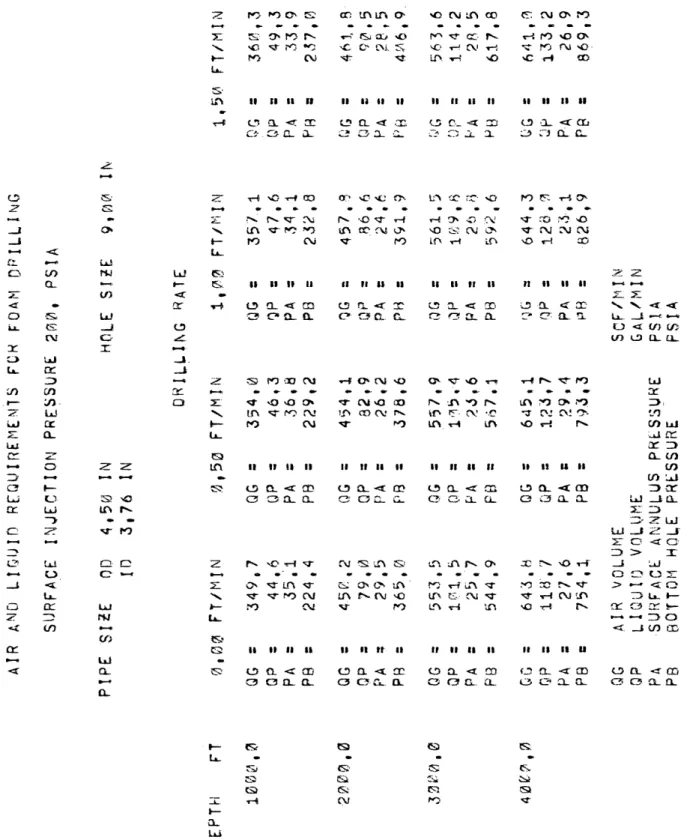
With the use of the Colorado School of Mines PDP-10 computer, the Bingham plastic model was applied to a foam drilling system. Various pipe and hole sizes were used in the drilling simulation. Surface injection pressures of 200, 300, and 4-00 psi, depths of 1,000, 2,000, 3,000, and M-,000 ft., and drilling rates of 0.0. 0.5, 1.0, and 1.5 fps were run on each pipe and hole combination. The tabulated r e sults are listed in the Tables section of this paper. The surface injection pressure, hole size, and tubing s i z e .determine which of the tables should be used for foam drilling. After the proper table is selected, the required air volume rate, water volume rate, and surface annulus pressure for various depths and drilling rates are read for a stable foam drilling operation. The engineer may match the output of the on-site equipment with the tabulated results of foam theory and thereby ensure a stable foam drilling operation.
Figures 6 and 7 represent a typical application of the tabulated results. Prior to drilling a hole with foam, the hole and drillpipe size have been selected, and the surface injection pressure is usually dictated by the source of the gas: i.e., field gas or compressor. With the use of the proper tables, the gas and liquid volume rates and surface-annuius pressures are plotted as shown by the data in Figure 6. Table 20 shows that as the depth increases, the air and liquid volume rates must be increased while the surface-annuius pressure must be
.SUBFACE ANNULUS ’PRESSURE ■ ( psi ) o \£> o o or> c o o o r - J O rH ^ -=t o +> o o o n3 *H o m o o -p o o o o • H O £ X >-~ o o o o o o o o o 00 oN o o'•A ^ro 0*Vo
AIR VOLUME RATE (scf/m)
o -*• o evil oo r - l o GO O
----O o o o in -o o o o oo on o CO ■<o ho G C «H •H r - j O ' r H * f \ •H o jh UN O s> '& N iTj . H C CO Cx„ & $~i . Pi O -r-4 Pe, fL O'J -P orH .. G . w O p* c v G; <2> o K o •r-4 cv9 •• ,C3 Cxi cH s> EH m C H fL 1—; CG •H as u3 CJ? m Q M T3 O vQ Sta *r| O O 3 * G CT O CU •T.J <0 c N o t.1 ♦H ■>H G 01 -P < O a> <U ?-< rH T ? •H o >** <s I—1
AIR VOLUME RATE (scf/m)
o O
Ov
O
T-1383
decreased. As the drilling rate increases, the air and liquid volume rates must be increased, and the surface-annuius pressure must be decreased, By displaying the volume and pressure requirements in graphical form, the adjustments in the field equipment may be deter mined easily and quickly for the changing depth and drilling rate. The air volume rate in Figures 6 and 7 represent a confidence interval for the drilling rates, The air volume rate is changing with depth and drilling rate, but the amount of change is too small to be seen on the figures.
Calculations show that the minimum hydraulic horsepower for foam drilling will be attained when the lowest available surface in jection pressure and the largest drillpipe applicable to a hole is used. At higher surface injection pressures, more air is required; therefore the hydraulic horsepower is increased. The use of the 1 cLP gest drillpipe will minimize the hydraulic horsepower since the large drill pipe has less frictional losses- than small pipe and will therefore require less horsepower, In order to minimize hydraulic horsepower in a foam drilling operation, the minimum surface injection pressure and the largest drillpipe should be used.
The range of the maximum Reynolds number in the pipe is 609 to 104,000 for the various pipe and hole combinatipns. The range of the maximum Reynolds number in the annulus is 1 to 22,000. The maximum Reynolds number for the pipe and annulus is at the bottom of the pipe. At this point, the effective foam viscosity is at a minimum, the density
is at a maximum, and the velocity is at a minimum. The effective vi s cosity is extremely low and is the controlling number in the Reynolds calculation. The Reynolds number at this point is therefore a maxi mum. It should be noted that the majority of the Reynolds numbers are less than 2,000 and the flow.is assumed to be in the laminar flow regime. The equation which was used to calculate the Reynolds number in the pipe is
D.'Yp
Re = — — 45
T D. where y = y +
e p 5V
and in the annulus is
Re - a 46
v e
T W where y = y + Trrr-
e p 4 V
It should be noted that a Reynolds number criteria of 2,000 for de fining turbulent flow of foam has not been verified by experimental work.
T-1383
CHAPTER FIVE DISCUSSION OF RESULTS
The data show that for an increase in depth, the water and air volumes must be increased while the surface annulus pressure must be decreased if the boundary conditions of 0.96 surface-annular
quality and 1.5 fps bottom-hole velocity are to be maintained for the various depths. As the depth increases, the bottom-hole pressure will also increase while the gas volume will decrease. The velocity will therefore decrease. In order to maintain a velocity of .1.5 fps at the bottom of the pipe, the quantity of air must be increased. With the increase of air volume, there must be an associated increase of 'water volume if the surface quality Is to be 0.96, The annulus surface pressure also affects the foam velocity and quality. If the annular pressure is not decreased with an increase in depth, larger water and air volumes will be required if the imposed boundary conditions are to be satisfied, The reported surface-annular pres sures are the minimum pressures required if minimal air and water volumes are to be used in a foam drilling system.
For a specific depth, as the drilling rate is increased, the air and water volume rates must be increased and the annulus surface pressure must be decreased if the boundary conditions are to be met. As the rock chips are picked up and carried out of the annulus, they will add to the f oa m ’s density and increase the bottom-hole pressure. For higher drilling rates, the bottom-hole pressure will
be larger; larger volumes of air and water will be required. As was stated in the last paragraph, the required air and water volumes are minimal volumes, based upon the minimum annulus surface pressure for each group of data.
T-1383
CHAPTER SIX
CONCLUSIONS AND RECOMMENDATIONS
The purpose of this study was to present a mathematical model and its solution for the application of foam in a drilling system. The mathematical model of foam is the Bingham plastic fluid model applied to a compressible fluid. The Bingham model has been written in an iterative form and solved with a constant pressure iteration for a concentric vertical hcle-annulus arrangement, Two equations have been written: one describing flow down the pipe and one d e
scribing flow up the annulus. The following conclusions may be stated about the mathematical model for foam:
1. The foam plastic viscosity is defined for a range of 1 to 14.7 cp for all qualities from 0 to 0.96.
2. The foam yield stress is defined for a range of 0 to 359 cp for all qualities from 0.584 to 0.96.
3. Foam plastic viscosity^ and yield stress_ar.e„undef ined in the mist region.
4. Maximum annular foam quality should not exceed 0.96.
5-. All bottom-hole annular velocities may be used in the model, but computer time increases with higher velocities.
6. As the velocity increases, the foam properties will change such that smaller pipe lengths are required for the same change in pressure.
7. The optimum bottom-hole velocity has not been determined.
8. Temperature effects on foam stability have not been investigated,
9. Rock chip volume and mcjss have been accounted for in the quality calculation.
10. Solutions for pipe sizes of 2.87 to 4-.50 in O.D. in hole sizes of 5.75 to 15.0 inches have been calculated.
Since the results of this study are based upon ideal drilling and hole conditions, the best test of the results would be an actual drilling application. It is recommended that the following items be investigated:
1 The bottom-hole velocity of 1.5 fps should be checked to determine if the velocity is sufficient to clean the rock chips from the bottom of the h o l e .
2, The actual pressure drop in the system should be checked against the theoretical calculated pressure change. In this manner, the Reynolds number for foam may be calculated and-
its effect upon the plastic viscosity and yield strength be determined,
3. Since the slip velocity in foam was assumed not to exist, a laboratory investigation should be made to verify this assumption,
A IR A M r; L IQ U ID R E Q U IR E M E N T * F U K F O A M [) RI LLI NG
T-1383
~£. r ^ r ^ N O ' O co ■>-? sr vc cv . n ' r vo r>- ir> c" y ~ ' co cv _o o 10 c-: *0 cv yj X' x cv -»-i x cvi cv cv -sf r*z> is, in n h it it ti it 11 11 -r-f o a < re o c l <r rr 3 0 cl a,. o cj a. cl II II U It II II it II It 0 rv <s X- 3 X GO 3 r>i X a 3 ;~r.O X O oc c v in CO x> vO vr « m- • * m •• » •> •x rr> v—tm ro CO c v V c v or.'. JO*0 CvJ vO x . cv 0 c v c v c v c v fO ro It II if II II II It It it 0 CL < rr 0 a -*3T X e> X o_ r~-s rv r> V CV X 0 -;q • 0 V 53 X-fO Cvi *r> V—f 3 ir\ ro 0 cz x> ro c v X 3 '. Cvi CO — : c v cv CV r o ro u 11 II It II 11 II 11 it 0 Cl c X 0 a . < CD 0 0 C5 CL CL <3 0 rv CL O it it i> iitry t* cva^r^p'^p'-r^^ro' r-tva
. . . .
« • - -
. . .
- \x. x ^ 3 O X> ;V .XS r> * 0 . 0 s X 'O 'x. k o *o cv x x cv rv N n < t- CV Cv CV V- f>0 <S X *— Lj C/' UJ s a — 1— e CO <t — L w-e? u* 3. 3 O cv o 3 X *—• ui 3 £T 3 3 •-* ^C « C\1«J- N m c O X I ' O sr f O H co :r — co o r uj \ at i— X u. 3 x- tn 13 c o -x -> * • cv 00 3 O O X V CV X 3 CO •'O V CO X - •> J O O o o — • — * < X 3 GC 3 S-3 rv* 3 CO •— CO CSC 13 0 3 O ' ro 03 • • •• » O' trv cr_> cv CV ^r C iO cv cv vC ro 0 11 11 11 II II X* 3 X < m X 3 X X "■K IT* 0 cv T—i • £: CO cv cv nO 00 cv 0 X fO x» i i If II II if •—r X 3 . rrt 3 X < CD N \ 'X <T a fT*- c? X X X 3 O <1. C-) CO CO f—' cl a NO r-{ sO m CO 3 • m 0 — — L£ X X V JO z>< fSS nO CO cv tr \ 00 NO to CO CO 3 X * GC X 3 X CO II 11 It It 11 CO C/33 CD 3 X < CO 3 X X . CS c? 0 - r; 3 3 G_ L_ 3 —3 *Z UJ 3 3 vc 3 L O <t c ~v > X O cv V St 03 E 3 O C.1- O 5Z c cv rSJ- > ♦—* •c O cs ■V co cv f'v 3 X i -XV ro CC- c r O cr b-r 3 0 •< 3 00 X'. t« 11 11 11 11 CD O CL <t X 0 a c cr. a. 3 a X 0 C3 X X h - es.: 157 Cvv u. - - - -S3 ts. ?S 3 3 3 <3 S* O . cs. C3. 3 X . <r-t CV t*j V I— x 13 r~'y+
T A B L E 3 A IR AM O L I 0 U I 0 R E Q U IR E M E N T 3 FO R F O A M B I L L I N G or '-s *o s- vO s m >c - < H S o ro vO o 3 f— U ?o in o in T-v CV ;T. S r o r o C : X \ CO re v ro cv ro *r t-? cv ro o vO -o cv ro o T—i t-> CO T-5 •_r> cj s r -sr oo in ii ii u ii ii u 11 II II II II ii II O' Ci_ 3 X cn p. o 30.X'-TXX C?-L0 r \ <r X o o n it ii ii CO D. s ro cr u to CD UJ or X o UJ 3 LU o < u. c r co r-o U J cr. UJ _J o z z tn co -va ry cv U J ru co UJ o_ U ir o a "iC r r n r- «r •.fs •— I re fO JD rs n CO V r*i CJ G o CV V— u_ ?o rc- ro S-ss II II II ii II -I—i o X < CD LD 3 X X C ' z CD S* vO G T •— « <* • • •> • 5L ■o r» vr JTv <3 X x -i CV 00 -s XI s— u_ fO ro ro S? m II II II it it Si o X < X C3 o <3 X X C3 co s ro C’v LO-•— • • • • w * fO ‘.n rr> X! V N T-f cv o s cv 1— U ro PO ro Si Si II •1 II II ii 1?: • x < CD o o C? X X <3 to rv cv II II It II sr ^—i o .rv ^ rv o 3 I I U I t I i <r co X. CL m rv gtj -vr O' ro ii ti ii ti T-t tr- rs rx. O IT; O S JO VO II II If II C5 Q_ <4 CD O O CL. r n " o o in r> ii ii ii it LO. *'0 O rc co ro o - ^ s.- *3-<J '0?0 ri S T CO C 3. < II z X X 'v. X u . 3 •— « <£ CO LO 3 o . tn r o S T-K r-f UJ • » » • * X 51 s O X> V r o z> O rr ■C V O cn in v r r - < /l UJ Ui X X 3 x cn it IT 11 I I ii n C/5 UJ Xv C!> X . - c CD 3 X X CJ, 3 X X UJ _ t x X 3 3 U I UJ 7T __i ■*? o •<t O z> > X r / ns ^ -* ro in __r u • - • - o O 51 JO CY c - r <r »—« c . o s r V > 'S? • o "X u r -in 'vr X O X 1— •—# •—« 3 O 3 Uj CD tl 11 a II ll II 11 11 ir •3 LO X <r 3 o x c X o x <r 3 X cr 3 X X C3 C3 X X 3 o X X X I— a. UJ o C3 is; s s is CV si «S! ro Si S-<3 S i v
T A B L E 4