Evaluating LoRa Physical as a
Radio Link Technology for use
in a Remote-Controlled
Electric Switch System for a
Network Bridge Radio-Node
Abdullahi Aden Hassan / Rasmus Karlsson Källqvist
K T H R O Y AL I N S T I T U T E O F T E C H N O L O G Y
i
Acknowledgments
We would like to thank our academic mentor Anders Västberg for helping us with the process of writing and carrying through this degree project, answering all of our questions, and for proof reading this report.
We would like to thank Amin Azari for showing genuine interest in our project and for answering some math questions we had when calculating the radio link budget, and for discovering that the formula in a book we were using had a printing error which was initially causing our results to be wrong.
Thank you to fellow students Michael Henriksson and Sebastian Kullengren for a thorough opposition to this report and for much helpful feedback in keeping the text readable and scientific.
Thank you to Björn Pehrson for representing AMPRNet Sweden and giving us the opportunity to work on this project, financing the system prototype and for giving helpful feedback.
Finally, we would like to thank program director Bengt Molin for teaching us much of what we know of embedded systems and for lending us equipment used in the development of the hardware prototype.
ii
Abstract
This report explores the design of a system for remotely switching electronics on and off within a range of at least 15 km, to be used with battery driven radio nodes for outdoor Wi-Fi network bridging. The application of the network bridges are connecting to remote networks, should Internet infrastructure fail during an emergency.
The problem statement for the report was “What is a suitable radio link technology for use in a remote controlled electrical switch system and how should it best be put to use?” To answer the question, delimitation was done to exploring Low Power Wide Area Network (LPWAN) link technologies, due to their prior use within power constrained devices.
Long Range-radio, abbreviated LoRa, is a LPWAN radio modulation technique and was determined to be a good candidate as a suitable link technology for the remote electrical switch system. The range of LoRa is achieved by drastically lowering the data rate of the transmission, and is suitable for battery-powered or energy harvesting devices such as those found in the field of Internet of Things. A LoRa-based transmitter and receiver pair was implemented, and measured to have a packet delivery ratio of over 95% at a distance of 2 km, measured between two bridges. Data at further distances could not be accurately determined, because of the LoRa transceiver giving faulty readings.
No conclusion could be made about the suitability for using a LoRa based system to solve the problem, partially due to an improper method for testing the radio performance was used, and partially due to an inconclusive measurement result. Keywords
LoRa; Emergency preparedness; Amateur radio; System design; Embedded system; Radio electronics
iii
Abstract
Denna rapport utforskar designen av ett system för att fjärrstyrt slå på eller av elektronik över ett avstånd på minst 15 km, för att användas med batteridrivna radionoder för nätverksbryggning utomhus med Wi-Fi. Tillämpningsområdet för nätverksbryggorna är att koppla samman avlägsna nätverk, om Internet-infrastruktur skulle sluta fungera vid en nödsituation.
Problemställningen för rapporten var ”Vad är en lämplig radiolänksteknik att använda i ett fjärrstyrt elektriskt strömbrytarsystem, och hur ska det bäst brukas?”. För att svara på frågan gjordes en avgränsning att utforska Low Power Wide Area Network (LPWAN)-länktekniker, på grund av deras tidigare användning inom effektbegränsade enheter.
Long Range-radio, förkortat LoRa, är en radiomodulationsteknik som används för att skicka data över långa avstånd med energibegränsade enheter. LoRa:s räckvidd uppnås genom att drastiskt sänka datatakten, och lämpar sig för bruk i batteridrivna eller energiskördande enheter, likt de som återfinns inom fältet Internet of Things.
Ett LoRa-baserat sändar- och mottagarpar implementerades, och uppmättes till att ha en paketlevereringsmängd på över 95% vid ett avstånd på 2 km, mätt mellan två broar. Data vid större avstånd kunde inte bli bestämt noggrant, eftersom LoRa transceivern gav felaktiga avläsningar.
Ingen slutsats kunde göras för lämpligheten för att använda ett LoRa-baserat system för att lösa problemet, delvist för att en olämplig metod för att testa radions prestanda använts, och delvist på grund av ett ofullständigt mätresultat. Nyckelord
LoRa; Krisberedskap; Amatörradio; Systemdesign; Inbyggda system; Radioelektronik
iv
Definitions
AMPRnet Amateur Packet Radio network
BW Bandwidth
CPU Central processing unit
CR Code rate
CSS Chirp Spread Spectrum
ECC Electronic Communications Committee ERP Effective radiated power
FEC Forward Error Correction
FRO The Voluntary Radio Organization GPIO General Purpose Input Output ID Identification
IoT Internet of Things
ISM Industrial, Scientific and Medical radio bands LCD Liquid Crystal Display
LoRa Long Range
LoRaWAN LoRa Wide Area Network LoS Line of Sight
LPWAN Low-Power Wide-Area Network MCU Microcontroller Unit
MSB Swedish Civil Contingencies Agency NF Noise Figure
PCB Printed Circuit Board PDR Package Delivery Ratio
PL Payload
PTS Post and Telecommunication Agency RC Remote Controlled
RSSI Received Signal Strength Indication SF Spread Factor
SK0MT Call sign for the radio amateur club Täby Sändaramatörer SNR Signal-to-Noise Ratio
SPI Serial Peripheral Interface
v
TABLE OF CONTENTS
1 Introduction ... 1 1.1 Background ... 1 1.2 Problem... 1 1.3 Goal ... 2 1.4 Purpose ... 3 1.5 Methodology ... 3 1.6 Delimitations ... 3 1.7 Disposition ... 4 2 Background ... 52.1 Emergency management of telecom in Sweden ... 5
2.2 Amateur radio resources in emergency management ... 5
2.3 Internet access via radio amateurs ... 6
2.4 Outdoor network bridging using battery driven radios ... 6
2.5 The network bridge attempted by AMPRNet Sweden ... 7
2.6 Technical description of the battery-driven radio node ... 8
3 Method ... 9
3.1 The design-science research methodology ... 9
3.2 Applying the methodology to this study ... 10
3.3 Literature study ... 11
3.4 Prototype system design ... 11
3.5 Implementation of hardware ... 11
3.6 Implementation of software ... 12
3.7 Test of prototype system ... 12
4 Literature Study ... 13
4.1 Ingenu Ramp ... 13
4.2 LoRa (Long Range) ... 14
4.3 SigFox ... 15
4.4 Telensa ... 16
4.5 Suitability for the technologies in the prototype ... 16
4.6 Related LoRa studies ... 17
4.6.1 LoRa Mobile-To-Base-Station Channel Characterization in the Antarctic....17
4.6.2 Range Evaluation and Channel Attenuation Model for LoRa Technology ....18
4.6.3 Performance Evaluation of LoRa Considering Scenario Conditions ...18
4.6.4 Summary of related studies ...19
5 Radio Link Theory ... 20
5.1 Transmission theory ... 20
5.1.1 Link budget and fading ...20
5.1.2 Free space propagation loss ...20
5.1.3 Okumura-Hata model for propagation loss ...21
5.1.4 Fresnel zones ...22
5.2 ISM-band regulations ... 23
5.3 LoRa parameter configuration ... 23
5.3.1 Spread factor ...24
5.3.2 Bandwidth ...24
5.3.3 Code rate ...24
vi
5.3.5 LoRa sensitivity ...26
5.3.6 Selection of LoRa parameter values for RC electric switch system ...28
5.4 Theoretical communication range ... 28
5.4.1 Link between SK0MT and Ullna landfill ...28
5.4.2 Link between Ullna landfill and Rindö Redoubt ...29
6 Implementation of Prototype ... 30
6.1 Goal of implemented prototype ... 30
6.2 Hardware components and assembly ... 30
6.2.1 STM32L1-Discovery development board ...30
6.2.2 RFM96 LoRa radio chip ...31
6.2.3 Flexi SMA90 Quarter-whip antenna ...31
6.2.4 Assembly ...32
6.3 Transmitter and receiver software ... 33
6.3.1 LoRa driver ...34
6.3.2 Transmitter unit’s microcontroller firmware ...34
6.3.3 Receiver units’ microcontroller firmware ...35
6.4 Validating functions for determining RSSI and SNR ... 36
6.4.1 Code snippets ...36
6.4.2 Validation of statistical functions ...37
7 Simulations and Field Tests ... 39
7.1 Simulating performance of radio links using Radio Mobile ... 39
7.1.1 Simulation settings and sites ...39
7.2 Measuring radio LoS-performance using local bridges ... 40
7.2.1 Considered measurement sites ...40
7.2.2 Used measurement sites ...41
7.3 Characterizing the RFM96 RSSI meter ... 41
8 Result ... 43
8.1 Simulation results ... 43
8.2 Bridge measurements... 45
8.3 Ground measurements ... 48
8.4 RSSI characteristics ... 49
8.4.1 Data read from RSSI chip ...49
8.4.2 RSSI characteristic curve with antenna equipped receiver ...51
9 Discussion ... 52
9.1 Interpreting results ... 52
9.1.1 Radio Mobile simulation of radio links ...52
9.1.2 Packet delivery ratios when measuring between bridges ...52
9.1.3 Incorrect RSSI and SNR ...53
9.1.4 Microcontroller RSSI readings and processing ...53
9.2 Other suitable measurement methods ... 54
9.3 Evaluation of chosen research methodology ... 54
9.4 Future work ... 55
9.5 Conclusion ... 55
1
1 Introduction
This report documents a design process for a remote-controlled electric switch system that was commissioned by the association AMPRnet Sweden. The association had used battery-driven radio equipment that discharged its batteries to quickly in stand-by mode, and wanted to be able to turn the electronics on and off as needed.
The introductory chapter will present the background leading up to the commissioning of the electric switch system, present the problem this report investigates and describe how a prototype system was to be developed.
1.1 Background
The association AMPRnet Sweden is working with the construction of a backup Internet infrastructure in Sweden using radio amateur resources, as an aid to Swedish emergency preparedness agencies.
Those resources take the form of the radio amateurs themselves, who have competence in using and managing communication technologies, and the equipment that they have available. One of the technologies that AMPRnet Sweden is interested in is outdoor Wi-Fi network-bridges, which can be used to physically connect two remote networks in the case that local IT infrastructure fails.
The network-bridges are formed with directional microwave-radios, and can cover great distances given a line-of-sight between transmitter and receiver. If two sites that need a connection does not have a direct line-of-sight, then radio nodes can be placed at intermediate sites where line-of-sight exists.
To ease the deployment of these intermediate radio nodes, they can be made portable by equipping them with batteries and solar cells. An experiment of such a setup was carried out by AMPRnet Sweden, attempting to connect the radio amateur club Täby Sändaramatörer and nearby Vaxholm Fortress with two intermediate battery powered nodes.
The experiment failed, when it was discovered that the radio equipment drained the batteries too quickly in standby mode, and a need was identified to be able to remotely turn the equipment on and off.
1.2 Problem
At its core, the problem this report investigates is making sure that power isn’t needlessly drawn from the radio nodes’ batteries. To accomplish this, a suitable system for switching electronics on and off remotely should be developed.
2 Such a system would have several aspects that would have to be investigated in order for it to function, topics such as:
• User interface that the operator can use to request deployed nodes to switch its electronics on or off.
• Protocol that dictates the format of those requests.
• Suitable radio link technology to broadcast the requests from the operator to the nodes.
• Access from the base node of the operator to all other deployed nodes through some network topology.
• Security mechanism that authenticates a request from the operator to a node, and protects the system from third-party attacks.
• Low power consumption, so that the electrical switch system doesn’t drain the batteries in any significant way.
All of these aspects are dependent on each other, and a good system design must take all of them into consideration. When making choices for one part of the system, such as the security mechanism or the radio link, one has to also think about how that choice influences the rest of the system and their ability to achieve the goal of reducing power consumption in the radio node.
The problem of making the design therefor becomes finding the best possible decisions for all the parts of the system with regards to their relation to each other and how they contribute to the overall system function.
To solve the design problem, the design can be broken down into several parts and focused on individually. The result of a study of one part could then inform the design decisions for the rest of the system.
This report therefore explores the question “What is a suitable radio link technology for use in a remote controlled electrical switch system and how should it best be put to use?”
1.3 Goal
The goal of this study is to find a simple proof of concept of the remote controlled electrical switch systems link-technology, by creating a design, implementing it, and then testing its performance.
This proof-of-concept should then serve as a foundation for a more elaborate and complete design, that could be used in the actual AMPRNet Sweden radio nodes. In the problem scenario of the Täby–Vaxholm network bridge attempted by AMPRNet, the furthest distance between radio nodes was 15 km. Therefore, the proof-of-concept should let an operator communicate with nodes separated at up to at least 15 km.
3
1.4 Purpose
This report is written in order to document the findings of a suitable low power radio link technology’s performance in a real-life scenario, and to contribute to the capabilities of AMPRnet Sweden to provide in emergency management of IT-infrastructure, yielding a social benefit.
The application of the switch system is in the AMPRNet nodes, but could easily be generalized to any distributed system of hardware which power state needs to be controlled remotely. There is therefore a possible environmental benefit from the system explored in this report.
1.5 Methodology
The methodology employed in this project is Design-Science Research, as described by Hevner et al, where “knowledge and understanding of a problem domain and its solution are achieved in the building and application [a] designed artefact” [1].
Design-science when applied to developing a prototype system as described in the earlier sections becomes thoroughly designing, implementing and testing a system to better understand the constraints of the problem scenario, and the possibilities in solving it using the proposed prototype system.
1.6 Delimitations
Due to the time constrained nature of the project, some delimitations were imposed.
The focus is on implementing a system that could communicate between two neighbouring nodes. No attention is given to exploring security mechanisms, and only limited attention to power saving features. Additionally, the prototype is not given any capability to interface with any radio node electronics, focusing completely on the radio link.
For the communication between the network operator and the radio nodes, the focus was on multi-hopping between radio nodes in series rather than one powerful sender at the operator broadcasting to all nodes. This simplified implementation, since there was no easy access to powerful broadcasting equipment during conduction of this research.
The mathematical model for the problem scenario was kept simple, in-depth enough to make an informed decision when choosing radio system parameters, but not accounting for every detail.
Finally, the evaluation of the system was done so that it could give an indication of the radio channel’s performance, but not to thoroughly characterize it.
4
1.7 Disposition
The rest of this report is followed first by Chapter 2, which describes the association AMPRNet’s role in Swedish emergency preparedness and their network bridge experiment between Täby and Vaxholm in more detail.
Chapter 3, Method, describes how the LoRa-based design was to be developed and tested and how LoRa came to be the chosen radio link technology for the project.
Chapter 4 describes the mathematical process of deriving the choice of parameter values such as transmission power for the LoRa radio link to maximize the range of transmission. Chapter 5 describes the implementation of the proof-of-concept prototypes hardware and software.
The validation of the prototype is described in Chapter 6, using simulations and a field test carried out between various bridges in Stockholm. Chapter 7 describes the result of those simulations and test measurements.
Finally, chapter 8 will discuss the result of the simulation and field tests and try to determine whether the LoRa-based design successfully laid the groundwork for a more complete implementation of the remote controlled electrical switch system, or if another link technology should be used.
Chapter 9 concludes the report with what has been learned, and the potential for future work within the problem area.
5
2 Background
This background chapter will present how Swedish state authorities work with emergency management of electronic communication and how radio amateurs are contributing to the agencies work.
The association AMPRnet Sweden will be introduced, that work with using radio amateur resources to secure Internet infrastructure, along with describing the attempt they made of establishing an outdoor network bridge between the radio club Täby Sändaramatörer and Vaxholm Fortress, using portable battery-driven radio nodes. Finally, the capabilities and principles of the radio technology LoRa will be described.
2.1 Emergency management of telecom in Sweden
Sweden is a connected country, increasingly relying on digital technology and electronic communication in industry, private life and public sector. In crisis preparedness, it is therefore of importance to make sure that infrastructure that supports electronic communication can withstand stress during an emergency. The Swedish Civil Contingencies Agency (MSB) is a government agency that is organized under the Ministry of Defence, that works with managing and containing emergencies in Sweden by supervising, supporting and educating other authorities, actors in private sector and members of civil society [5].
On behalf of MSB, the Post and Telecommunication Agency (PTS) therefore performs regular exercises with Swedish telecommunications operators to increase their knowledge and experience with crisis preparedness.
In a report produced by the PTS about their crisis response strategy for 2007-2021, they state that companies and parts of civil society that can support crisis preparedness should do so. The electronic communication sector was identified as of particular interest for this kind of preparedness [6, p. 18].
2.2 Amateur radio resources in emergency management
Amateur radio is a hobby where radio enthusiasts broadcast and listen to radio for non-commercial use. Practitioners are called radio amateurs, and usually practice in amateur radio clubs.
These radio clubs form a part of civil society that can collaborate with crisis management agencies, and provide support in an ongoing crisis, by offering expertise and equipment for electronic communication.
The Voluntary Radio Organization (FRO) is a defence organization for citizens who want to contribute to emergency preparedness for electronic
6 communications and is an example of amateur radio resources being used for that purpose [7].
Radio clubs regularly participate in exercises and education organized by the FRO and have historically contributed to communication during crises. Radio amateurs therefor demonstrably form a natural part of civilian emergency preparedness.
2.3 Internet access via radio amateurs
The Internet is an important form of electronic communication, and therefore a priority to secure in case of an emergency. Internet connectivity is usually provided by a telecommunications operator but can also be provided using radio amateur resources.
AMPRnet (Amateur Packet Radio Network) is a collection of computer networks maintained by radio amateurs, based on IPv4 and IPv6 addresses reserved for radio amateur use in the American 1980s. These networks can be used for educational purposes, or act as an access-network to the Internet in crisis situations where commercial alternatives are unavailable [8].
AMPRnet Sweden is an association that administers the construction of a Swedish extension of the existing American AMPRnet, with the purpose of, among other things, making radio amateur resources more accessible to Swedish emergency preparedness organizations.
Participating radio clubs are encouraged, in a pamphlet written by the association, to use any of their available link technologies to connect resources such as repeaters, radio stations and sensor networks to the Swedish AMPRnet [9].
2.4 Outdoor network bridging using battery driven radios
An AMPERnet base and a network on a remote location can be connected using a network bridge, which links the networks together. An example of such a link is 5 GHz WiFi over microwave radio, which transmits data in concentrated line-of-sight broadcasts that can reach several tens of kilometres.
AMPRnet Sweden attempted in collaboration with the radio club Täby Sändaramatörer (call sign SK0MT), as a part of an emergency preparedness event on Vaxholm Fortress in the nearby archipelago, to establish a network bridge between SK0MT and the fortress using these kinds of microwave radios.
7 SK0MT and Vaxholm Fortress do not have a direct line-of-sight, so two intermediary batteries driven radio nodes were used for the network bridge. One was placed on the top of the Ullna landfill nearby SK0MT, and the other on Rindö Redoubt (a 19th century military structure) adjacent to Vaxholm Fortress. Unfortunately, the experiment failed, because the radio equipment discharged the batteries while unused in standby mode. A need to remotely switch the equipment on or off when needed was identified.
Such a remote-controlled on/off-switch, or electric switch system, would need to use a secondary radio that would be powered continuously and that has a range similar to that of the microwave radios. To not significantly drain the batteries, this secondary radio would also have to consume very little power.
2.5 The network bridge attempted by AMPRNet Sweden
The network bridge that was constructed for the experiment that AMPRnet Sweden carried out during the emergency preparedness day on Vaxholm Fortress consisted of four nodes, of which two were intermediary and battery powered.
SK0MT acted as the AMPRnet base and Vaxholm Fortress as the remote network to bridge to. The intermediary nodes were used to establish a line-of-sight connection between the base and the remote network, and were placed on two elevated sites; on top of the Ullna land fill and the roof of Rindö Redoubt.
Most of the distance of the network bridge lie between the two intermediary nodes, which are separated by 15 km. SK0MT and the Ullna landfill are 4 km apart, and Rindö Redoubt and Vaxholm Fortress a mere 500 meters.
Figure 2, geographical location of the SK0MT—Vaxholm Fortress network bridge
The radio mast used by SK0MT is 40 meters tall and has a line-of-sight to the 60-meter high Ullna landfill. Rindö Redoubt is elevated 32 60-meters above water level, according to topographical data from topographic-map.com [10].
8 The terrain between SK0MT and the Ullna landfill is primarily low suburban housing, and the terrain between the landfill and Rindö Redoubt consists of mostly wood, open fields, some stretches of water and a few buildings. Rindö Redoubt and Vaxholm Fortress are separated by some trees and open water.
Figure 3, 3D renditions of the Ullna landfill, Rindö Redoubt (foreground, right) and Vaxholm Fortress (background, left) from Google Maps
2.6 Technical description of the battery-driven radio node
The Ubiquiti “Nanobridge” were used for the microwave radios that connected the radio nodes, which according to the Ubiquiti sales site has a range of more than 50 km in line-of-sight conditions [11]. Since these radios are highly directional, each intermediary node was equipped with two Nanobridges.
A 150-ampere hour 12-volt lead-acid battery powered the node, connected via a voltage regulator that also steps the voltage down to lower values for other loads. Such loads could include a Wi-Fi access point, which would allow users at an intermediary node to connect to the network.
Figure 4, technical components of intermediary network node
The Nanobridges draw 2 ampere each, which meant a continuous consumption of around 48 watts. A connected solar panel could charge the batteries via the voltage regulator, and the current battery level could be read by the regulator firmware [12].
9
3 Method
This chapter will describe the chosen methodology, and how it was used to construct a method for solving the problem of finding a suitable radio link technology for the remote controlled electric switch system.
3.1 The design-science research methodology
The method chosen for this project is based upon the Design-Science methodology that is described in the paper “Design Science in Information Systems Research” by Hevner, March, Park and Ram [1].
The basis for the methodology is the build-and-evaluate cycle, where a design artefact (such as a system prototype or a theoretical model) is developed to solve a problem, and then thoroughly evaluated to prove its usefulness.
Hevner et al propose that “knowledge and understanding of a problem domain [in information systems] and its solutions are achieved in the building and application of [a] designed artefact” [1, p. 75]. They put an emphasis on using the act of designing an artefact as a way to explore the problem to be solved, i.e. by figuring out how one part of the artefact should be implemented, a corresponding part of the problem can be solved.
Additionally, they claim that the produced artefact must be useful as well as innovative in the problem domain, in order for the research to be contributing something of value, by either solving the problem in a new way or in a more efficient way than before.
To achieve these goals, Hevner et al present a set of guidelines that they recommend design-science researchers to use [1, p. 82];
1. Produce an artefact that works functionally.
2. Attempt to solve a problem that would be useful to an interested party. 3. Evaluate the designed artefact thoroughly to prove its usefulness.
4. The artefact must be innovative, by either solving the problem in a novel way or by being more efficient than its predecessors.
5. Both the development and the evaluation of the artefact needs conducted scientifically, by applying existing proven theories.
6. The problem should be solved iterating through several build-and-evaluate cycles:
a. The problem should be formally defined using the theories of the problem environment, so that the solution space can be explored by attempting to develop an artefact that solves the problem. b. By evaluating the resulting artefact, a better understanding of the
problem can be achieved. The problem can then be more specifically defined, and a better artefact developed.
10 7. Communicate the research results from both a technical and business oriented perspective, so that the value of the research is clear to both technical and managerial audiences.
The authors encourage researchers to use as many of these guidelines as applicable, to conduct efficient design-science research.
3.2 Applying the methodology to this study
The problem that this study attempted to solve was finding a radio link technology that could meet the requirement of a 15 km line-of-sight communication range while consuming little power. Since this could be used to aid Swedish emergency preparedness of telecommunication, the problem is relevant (guideline 2).
By applying the link technology to a specific problem scenario (Täby-Vaxholm), a kind of case study is achieved, where insight in the performance of the technology in that specific scenario can be found (guideline 4).
A literature study was carried out to find a candidate radio link technology to use in the problem scenario of Täby-Vaxholm, that had been proven to work in similar environments. Related studies using that technology was then found to act as a basis for finding design parameters (guideline 5).
The Täby-Vaxholm scenario was then formally defined in terms of radio nodes and the link budget between them, to determine the transmission capability requirements on the link technology. The design parameters for the chosen radio link technology was then found, and its relation to the link budget formulated mathematically (guideline 6a).
Suitable values for the design parameters were found, and a mathematical model of the system was formulated. A prototype transmitter-receiver pair was then instantiated and configured to use the parameter values (guideline 1).
The prototype pair was evaluated by sending a transmission of groups of data packages and measuring signal strength and package loss at varying kilometre distances (guideline 3), and its results used to try and prove the correctness mathematical model of the system.
A simulation using the model of the system was done in the Täby-Vaxholm scenario using terrain data, to show that the system would meet the transmission requirements. By comparing the measured data to the expectations given by the mathematical model, the correctness of the model and the simulation can be evaluated (guideline 6b).
The introduction and background chapters of this report presents the relevancy of the problem to a non-technical audience, and is followed by a more technical description of the work in the following chapters (guideline 7).
11
3.3 Literature study
A literature study was made to decide upon a radio link technology to use in the system, focused on low-power wide area network (LPWAN) link technologies. LPWAN was selected because of its focus on energy efficiency and long range. After selecting a LPWAN-brand, in this case LoRa, the literature study focused on the characterizations its parameters to understand what affects its performance.
3.4 Prototype system design
The design of the prototype system consisted of selecting a radio link technology, a data processing unit (such as a microcontroller or an application-specific integrated circuit) and an antenna that were suitable for achieving the goal of lower power consumption in the radio node.
The link technology and antenna was chosen to together support a transmission range of 15 km, and the data processing unit selected to be energy efficient. The LoRa transceiver has several configurable parameters, which were adjusted to maximize the range.
To evaluate the suitability for the link technology in the electrical switch system, the radio performance was to be measured with three quantities; received signal strength indication (RSSI), signal to noise ratio (SNR) and packet delivery ratio (PDR).
The software was designed specifically for field testing, where two radio units could communicate with a series of packets of a fixed size, and RSSI, SNR and PDR could be measured.
3.5 Implementation of hardware
The ‘Discovery’ development board for the STM32L152 microcontroller was selected as data processing unit, for its low power consumption and the familiarity of the implementers with the platform. Additionally, the development board had a built in LCD display suitable for feedback to a radio unit operator during tests.
HOPE Microelectronics RFM96 radio chip was used as LoRa transceiver, and was selected because of its affordability and availability as a breakout board easily connected to the Discovery development board.
In order to minimize the number of additional components needed at each radio node, it was decided to attempt the implementation with a single omnidirectional antenna instead of a directional antenna (which would require several antennas in the node).
12
3.6 Implementation of software
The software was based on LoRa drivers written by Sandeep Mistry for the Arduino brand of microcontroller development boards [ref]. The drivers were partially ported to the STM32 microcontroller, and used to configure radio parameters, transmit and receive packets, and extract RSSI and SNR values from the LoRa transceiver chip.
Additionally, software was written to measure the PDR and to give a user interface for the field testing to configure the number of packets to send. To measure RSSI, SNR and PDR, several packets were sent in groups of 10, 100 or 1000 row to be able to gather statistics of the measurements.
By basing the software implementation on an existing library, development time was shortened, and focus could be put on the evaluation of the link technology.
3.7 Test of prototype system
When the implementation of a transmitter unit and receiver unit was completed, a short test was performed indoors to verify that they could communicate with each other.
A statistical function was used in the software to calculate mean and standard deviation of SNR and RSSI, and was verified for correctness by comparing test data to output from the math software Mathematica.
The field test was carried out by standing with transmitter and receiver on tall bridges in central Stockholm separated by a couple of kilometres, to be able to measure radio performance at longer distances with a free line-of-sight between transmitter and receiver.
The collected data was then to be consolidated and used to create a model of the signal strength as a function of distance, to determine if the system could receive packets at the desired distance of 15 km using LoRa with the configured parameters.
Additionally, a simulation of the performance was made based on the receiver signal strength sensitivity that had been calculated for the parameters in the actual problem scenario with consideration for terrain.
13
4 Literature Study
The previous chapter presented the method for the study, where the first step was to determine what link technology to base the remote-controlled electric switch system on. This chapter will present the findings of the literature study that was made, and its conclusion to use the LoRa-brand technology.
Low Power Wide Area Networks (LPWAN) is a type of network that the Internet of Things (IoT) research community has shown interest in [ref], and because of the electric switch systems similar power constraints and range requirements to IoT-devices, was chosen as the topic for the literature study.
The goal of LPWAN technologies is to achieve connectivity between power-constrained devices in a wide area, such a house or a neighborhood or a city [ref], and does this by significantly lowering the communication data rate of the devices.
As a basis for the literature study, the paper “Low Power Wide Area networks: An Overview” by U. Raza and P. Kulkarni was used [13]. In the paper, they present the design goals and techniques of different LPWAN technologies, and discuss their similarities and differences to each other. Interesting technologies mentioned in that paper were then further researched individually.
The LPWAN technologies that were considered for the electric switch system was Ingenu Ramp, SigFox, LoRa and Telensa, presented here in alphabetic order. The chapter ends with a discussion of the technologies, and the selection of one of them.
4.1 Ingenu Ramp
In the LPWAN-market, a fairly new growing technology is a company called Ingenu Ramp. One major reason is their spread spectrum method, which is different from other LPWAN technologies, they use Random Phase Multiple Access (RAMP) to operates in 2.4 GHz ISM bands (which means that IEEE 802.11 used as media access control protocol and physical layer), this providing more relaxed spectrum usage rules and at the same time no architecture changes is required for sub-GHz technologies i.e. That Ingenu Ramp can be easily integrated with existing networks.
Another reason is that other company’s such as LoRa and SigFox are more designed for smaller packet size delivery then Ingenu Ramp, but they fail to have enough capacity or distance to build a cost effective wireless network model compare to Ingenu Ramp. [14]
For uplink communication, Direct Sequence Spread Spectrum (DSSS) is used for multiple access points. This kind of transmission technology is usually used in
14 local area, and benefits are resistance to jamming, sharing signal channels among multiple users, and less background noise.
For downlink communication, a modified Code Division Multiple Access (CDMA) is used, that allows multiple transmitters to share on a single time slot. However, RPMA extends the traditional time slot for CDMA, so that access for each channel gets a random delay for each transmitter. By not giving the transmitter direct access to channels, which reduce the overlap between transmission signals while increasing the signal in interference ratio for each individual link. This allows for more robust transmission control and higher sensitivity capabilities, better general coverage, and optimum battery life use. [13, p. 8]
4.2 LoRa (Long Range)
A relatively new technology that promises energy efficient long-range communication is LoRa, which falls under the category of Low-Power Wide-Area Networks (LPWAN). LoRa was developed by the French company Cycleo, that was later acquired by the California based company Semtech, and is marketed as an enabler for the Internet of Things (IoT) [15].
LPWAN achieves low power consumption and long range in exchange for lower data rates between devices and network gateways, which can extend the battery life of power constrained devices like those found in IoT and sensor networks. LoRa consists of a proprietary physical layer modulation scheme (“LoRa”) and an open media access protocol called LoRaWAN. The physical layer LoRa is based on a spread spectrum modulation technique called Chirp Spread Spectrum (CSS), where data symbols are encoded in tones that sweep either up or down in frequency.
Figure 5, LoRa up- and down-chirps in the time domain
During encoding, the carrier frequency of the signal is repeatedly swept either up or down, which generates so-called up-chirps and down-chirps. Being a spread spectrum technique, it utilizes the entire allocated transmission bandwidth to broadcast, which makes it robust to signal noise. Additionally, since the symbols are encoded with a continuously changing frequency, the transmission is also resistant to fading caused by the Doppler effect.
The three primary user-configurable parameters of LoRa are Bandwidth (BW), Spread Factor (SF) and Code Rate (CR). Bandwidth determines the speed at which the chirps are sent, and spread factor determines how many chirps are
15 used to encode a single bit, with higher SF yielding slower data rate but more reliable signal (with available values between 7 and 12). [16, p. 2]
Code rate is used to determine the ratio between payload bits and error-correcting redundant bits (usually a ratio of 4/8) that makes the transmission more robust. These parameters will be further explained later in the Theory & Design chapter.
In studies carried out to characterize LoRa, empirical data has shown that commercially available LoRa radio chips are capable of at least 30 km line-of-sight communication [2][4].
4.3 SigFox
The French company SigFox is another relatively new technology that falls under the category of Low-Power Wide-Area Networks (LPWAN). SigFox is one of the world’s leading IoT-service providers of energy efficient devices, such as wireless indoor temperature meters, alarm sensors, Arduino and etc. [17]
SigFox consists of a proprietary physical layer that is based on ultra-narrow band (UNB) technology and a media access protocol called Random Frequency and Time Division Multiple Access (RFTDMA). [18]
SigFox is cellular, and uses a star topology with nodes connected to in average three SigFox base stations. The base stations are connected to SigFox IoT-network, which provides a associated cloud service for data processing. [19] There are several advantages to use UNB’s property to increase the distance of the signal; one reason is UNB receivers listen to only a small part of the spectrum and therefore capture less noise, which in turn leads the signal to reaching longer. Another advantage of UNB is that a receiver uses a step filter that efficiently interrupts sideband disturbance.
During transmission, the broadcaster uses binary data to encode with a differential binary phase shift keying (DBPSK) modulation at a very low rate, and then SigFox’s nodes uses a RFTDMA to forward the signals. Additionally, frequency hopping spread spectrum (FHSS) is used to provide multiple access points, and ensures channel diversity by transmitting three times for each device on different and randomly selected UNB channels and this also gives protection against deep fading.
For reception, Gaussian Frequency Shift Keying (GFSK) is used. GFSK allows the user to filter data pulses with a Gaussian filter to make the transmission smoother and reduce side band power, and reducing the interference of nearby channels due to inter-symbol interference (ISI). ISI is a signal distortion in telecommunications and occurs if one or more symbols cause noise or less reliable signal. Multiple propagation and nonlinear frequencies in channels are the main cause.
16 SigFox has been characterized with a transmission range in urban areas of 10km and in rural areas of 30km. [13, p. 7]
4.4 Telensa
A less widespread fairly new technology that promises energy efficient long-range communication is the company Telensa. They focus more on developing wireless smart house control system and is one of the world’s leading manufacturers in the area; intelligent street lighting solution. The company uses something called PLANet to communicate with central management system (CMS) and outdoor device networks (ODN).
Telensa has chosen to collaborate with the TALQ consortium, which is a company that is working with implementing a global acceptance standard for management software, to be able to control and monitor outdoor device. The goal is to enable interoperability between (CMS) and (ODN) from different providers, so that only CMS can control some ODN in different parts of a city, or region depending on the populations regulatory needs of lighting or other requirements. [20]
The physical layer consists of bi-directional ultra –narrow band (2-UNB), which operates in unlicensed sub GHz ISM band(in EU 868 MHz, US 915 MHz and Asia 430 MHz), and has an uplink of 62.5bps and downlink of 500bps, besides this, not much information exists about implementing the technology. [13, p. 8]
4.5 Suitability for the technologies in the prototype
A technical presentation of the different brands of LPWAN has been presented, and will be compared in this section to each other and considered for the remote-controlled electrical switch system.
Ingenu Ramp is suitable for areas already integrated into telecommunication infrastructure such as smart gate connectivity, intelligent lighting, and oil and gas automation. Ingenu Ramp does however rely on a private cellular network, and is therefore not suitable for crisis preparedness, where technologies need to be independent from the infrastructure that they are supporting.
LoRa is available both as a network-technology (LoRaWAN) and a radio link technology (LoRa physical). LoRaWAN is based upon LoRa physical and is proprietary and cellular, which makes it unsuitable for the same reason as for Ingenu Ramp. The LoRa physical technology can be used independently of the WAN, and LoRa can therefor offer the long range and lower power consumption required for the electrical switch system.
SigFox, similarly to Ingenu Ramp, uses a cellular network to connect devices via base stations. Since these base stations are part of a proprietary network service owned by the SigFox Company, it is unsuitable for the same reasons as Ingenu Ramp.
17 There was very little information found about Telensa in the literature study, and seems less widely used than the other technologies. It was there for difficult to find details about Telensa could be used practically in the project, and whether or not it was suitable. Because of that, Telensa was not chosen for the prototype. Although SigFox showed good range properties, and as such could be a candidate for the radio link in the electrical switch system, it is cellular and therefore could not be used in the multi-hop network topology chosen for the project.
Since LoRa has a 30 km line-of-sight range, and had off-the-shelf radio transceivers available, it was selected for the project.
4.6 Related LoRa studies
This section will summarize three papers written about attempts at characterizing LoRa that were found in the literature study conducted at the start of the project.
The first was carried out in the Antarctic, and focused on a line-of-sight condition, and the other two in Europe. One was done in Spain, were three different environments were considered (rural, suburban and urban), and the last in Finland in an urban environment and on water.
4.6.1 LoRa Mobile-To-Base-Station Channel Characterization in the Antarctic
Gaelens, Van Torre, Verhaevert and Rogier examined a LoRa radio link between a base station with a directional antenna and a mobile vehicle equipped with an omnidirectional antenna in the Antarctic, to determine the suitability for LoRa technology in Polar Regions.
The experiment was done using the Microchip DM164138 development board, equipped with a Microchip RN2438 LoRa transceiver, at both base station and mobile vehicle. The LoRa parameters were configured to 125 kHz bandwidth, 4/5 code rate and a spread factor of 12.
The base station was equipped with a 9-13 dBi gain directional antenna, and an omnidirectional antenna on the receiver. They transmitted 3-byte payloads at +14 dBm on both the 434 and 868 MHz bands, and measured received Signal-Noise-Ratio (SNR) and Packet Delivery Rate (PDR) at the mobile vehicle. The maximum range that was achieved was 30 km, with no package loss at all up to 25 km LoS.
The authors conclude the paper by stating that line-of-sight is an essential requirement for long range LoRa links, and that terrain elevation is the dominating factor that influences the reception. Additionally, they also state that their calculated link budget of 154 dBm implies that omnidirectional antennas could be used for both transmitter and receiver [2].
18 4.6.2 Range Evaluation and Channel Attenuation Model for LoRa
Technology
Petäjäjärvi, Mikhaylov, Roivainen and Hänninen conducted a study of LoRa in the finish city of Oulu on both ground, with the receiver on the roof of a car, and on water mounted on the radio mast of a boat, with the goal of determining the coverage of a commercially available LoRa transceiver.
They used a Kerlink IoT station as base station with a 2 dBi gain biconical antenna mounted on the University of Oulu’s antenna tower at an altitude of 24 meter from sea-level, and a LoRaMote equipped with a Semtech SX1272 transceiver as receiver.
The LoRa parameters were set to a bandwidth of 125 kHz, spread factor of 12 and an unspecified code rate value. Transmission was done using +14 dBm power on the 868 MHz band with frequency hopping on 6 channels (which increases robustness to interference). The payload size was unspecified.
Using a car moving around in the urban environment of Oulu, they achieved over 80% PDR at distances up to 5 km, 60% PDR between 5 km to 10 km, and a majority loss after 10 km. On water, the PDR was 70% at a distance of up to 15 km, with the maximum range with successful deliveries at 30 km [3].
4.6.3 Performance Evaluation of LoRa Considering Scenario Conditions Sanchez-Iborra, Sanchez-Gomez, Ballesta-Viñas, Cano and Skarmeta did a more throughout study of LoRa characteristics by taking into consideration different kinds of environments, and trying to find optimal LoRa settings for each one. They used an Arrow SmartEverything Fox development board as receiver mounted on the roof of a car, and used a Rising HF RHF2S008 development board equipped with a Semtech SX1301 LoRa transceiver as base station. The base station transmitted on the 868 MHz band at 14 dBm and had an 8 dBi gain sectorial antenna, and the receiver a 5 dBi gain omnidirectional antenna.
Prior to performing any real-life measurements, simulations of the system were done using the web-based service CloudRF, which gave a reference point for the experimental results [4].
The measurements were done in an urban, suburban and rural scenario in and near the Spanish city of Murcia. They used many combinations of different BW, SF and CR parameter settings to determine their impact on received signal strength and delivered package ratio.
The greatest distance that was achieved was 18.5 km in the rural scenario (which means less obstruction) using a spread factor of 12. The package delivery rate was observed to depend somewhat on the payload size, with smaller packages being delivered more reliably than bigger ones.
19 In the discussion chapter of the paper, they state that the best parameter configuration for optimized length is setting SF and CR to their maximum values, 12 and 4/8 respectively.
4.6.4 Summary of related studies
These three examinations of LoRa capabilities have all shown that the technology can be used to reach 10-30 km, using different commercially available LoRa transceivers in different scenarios. Common to all of them is the use of a high code rate and spread factor, and obstruction free line-of-sight conditions.
The result from these studies suggests that a LoRa transceiver could be used as radio channel in the electric switch system for the SK0MT—Vaxholm network bridge nodes, as long as a line-of-sight can be guaranteed, and proper antennas are used.
One important difference between this work and the ones mentioned is that the LoRa radios used for the electric switch system needs to be able to act as both transmitter and receiver due to multi-hopping between nodes in a chain. This implies that the antenna used for transmitter and receiver needs to be the same.
This study therefor examined how a LoRa channel using omnidirectional antennas performs, since this allows each electric switch equipped network bridge node to function with only one additional antenna.
20
5 Radio Link Theory
In this chapter, a simple model of the transceiver’s capabilities will be constructed, suitable LoRa parameters selected and an estimation of the systems communication range with those parameters given.
5.1 Transmission theory
One of the design aspects that haven’t been discussed yet is the particulars of the LoRa transceiver, the mechanisms that influence its communication range and the parameters that can be configured by the designer. This section therefor will introduce some fundamental transmission theory, that will later be applied to the SK0MT—Vaxholm scenario to determine the systems theoretical capabilities. All formulas and theory presented in this chapter is based on descriptions found in the book “Wirless Communication & Networks” by Beard & Stallings [21]. 5.1.1 Link budget and fading
The link budget is an expression of the relation between received signal strength, transmitted signal strength, and any system gains and transmission losses involved.
The logarithmic formula for the link budget is:
𝑃𝑟 [𝑑𝐵] = 𝑃𝑡+ 𝐺𝑡− 𝐿 + 𝐺𝑟 (1) where 𝐺𝑡 and 𝐺𝑟 are the system gains of transmitter and receiver (from antennas), 𝑃𝑡 and 𝑃𝑟 are the transmitted and received power and 𝐿 the sum of all involved losses (cables, propagation loss).
Fading is a significant part of the transmission losses in real life scenarios, and is an expression for the variation in signal strength due to interference when a transmitted signal is scattered on terrain and obstacles (multipath fading), or due to obstruction blocking the signal (shadow fading).
The lowest signal strength that can be detected is called the receivers sensitivity, and the amount by which the signal strength exceeds that sensitivity is called the fading margin.
5.1.2 Free space propagation loss
When a signal is propagating in the space between two antennas, the radio energy becomes more and more spread out geometrically. This causes a loss in signal strength related to the distance squared, as expressed by Friis transmission equation:
𝐿𝐹𝑆 = (4π𝑑 𝜆 )
21 with 𝜆 as the wave length of the carrier wave, and 𝑑 as the distance between the transmitting and receiving antenna in the same unit as the wave length. The free space path loss can also be expressed logarithmically as:
𝐿𝐹𝑆 [𝑑𝐵] = 20 log10(4π𝑑 𝜆 )
(3)
5.1.3 Okumura-Hata model for propagation loss
Real life broadcasting scenarios introduce fading onto the signal, which introduces much greater losses than would be predicted by the free space propagation loss.
There are sophisticated ways of carefully calculating the exact impact of fading in a particular scenario with techniques such as ray tracing, which are complicated and out of the scope for this text. As an alternative, models of fading based on empirical data can be used.
The Okumura-Hata model is a widespread such empirical data based model, and formulates an expression for the losses a signal experiences in urban, suburban and rural scenarios [22]. The estimated loss for an urban scenario of a medium-sized city is given by:
𝐿𝑢𝑟𝑏𝑎𝑛 [𝑑𝐵] = 69.55 + 26.66 log10𝑓 − 13.82 log10ℎ𝑡− 𝑎(ℎ𝑟)
+ (44.9 − 6.55 log10ℎ𝑟) log10𝑑 (4) 𝑎(ℎ𝑟) [𝑑𝐵] = (1.1 log10𝑓 − 0.7)ℎ𝑟− (1.56 log10𝑓 0.8) (5) where:
For a suburban scenario, the urban model is modified to account for the lesser amount of obstruction:
𝐿𝑠𝑢𝑏𝑢𝑟𝑏𝑎𝑛 [𝑑𝐵] = Lurban− 2 (log10 𝑓 28)
2
− 5.4 (6)
and for the rural scenario, further subtractions are made from the loss predicted in the urban scenario:
𝐿𝑟𝑢𝑟𝑎𝑙 [𝑑𝐵] = 𝐿𝑢𝑟𝑏𝑎𝑛− 4.78(log10𝑓)2+ 18.33 log
10𝑓 − 40.94 (7) ℎ𝑡 = height of transmitting antenna in 30–200 meters
ℎ𝑟 = height of receiving antenna in 1–10 meters
𝑎(ℎ𝑟) = correction factor for receiver antenna height in decibel 𝑓 = carrier frequency in 150–1500 Megahertz
22 5.1.4 Fresnel zones
Two types of fading have been described; multipath fading and shadow fading, that both depend on obstruction in the propagation path. The Fresnel zones are geometric expressions for the area where an obstacle would interfere with the signal.
Figure 6, illustration of first Fresnel zone
The Fresnel zones are cigar-shaped elongated ellipsoids placed between the transmitting and receiving antenna. If part of the transmission collides with an obstacle in a Fresnel zone, it will be reflected back slightly phase-shifted, causing signal attenuation at the receiver due to destructive interference with the non-reflected wave.
Each numbered zone forms a shell outside the previous and introduces an amount of phase shifting, with the first zone shifting the reflected signal by 0– 90º, the second zone surrounding the first and phase shifting by 90–270º, the third shifting by 270–450º, increasing by 180 º for each subsequent zone.
The radius 𝑟𝑛 at a point p on the surface of a particular zone is expressed by:
𝑟𝑛 = √
𝑛 λ 𝑑1𝑑2 𝑑1+ 𝑑2
, 𝑑1, 𝑑2 ≫ 𝑛 λ (8)
where:
Note that higher frequencies will have shorter wave lengths, and by effect, more concentrated Fresnel zones. Lower frequencies in turn result in larger Fresnel zone, which increases the likelihood of obstruction in the propagation path. By doubling the frequency, the wave length is halved, and Fresnel zone radius decreases by a factor of √2 as is made clear by the expression:
𝑟𝑛(2f0) = √𝑛 λ0 2 𝑑1𝑑2 𝑑1+𝑑2 = 1 √2√ 𝑛λ0𝑑1𝑑2 𝑑1+𝑑2 = 1 √2𝑟𝑛(f0) ≈ 0.71𝑟𝑛(f0) (9) n = Fresnel zone number
λ = wavelength of carrier wave
𝑑1 = distance from transmitter to point p in meters 𝑑2 = distance from receiver to point p in meters
23 When selecting the frequency for the system, care should be taken for the resulting Fresnel zone radius. However, as has been shown in Equation (9), frequencies that only differ in one octave have very similar radii.
According to Westcott and Coleman [23], the rule of thumb for Fresnel zone clearance is that the first zone should ideally be 80% clear of obstacles, but at the very least 60% clear of obstacles.
5.2 ISM-band regulations
LoRa transceivers usually operate on the license free Industrial, Scientific and Medicinal (ISM) frequency band for transmission. This band is free for anyone to use, but have regulated transmission powers and duty cycles (how often a device is allowed to transmit expressed as percentage of an hour).
The specific frequencies that are considered license-free ISM depends on the local regulatory agency. In Sweden, the PTS determines the regulation of radio transmission and which frequencies constitute ISM. An excerpt from the ISM-band regulation from PTS [24] is found in Table 2:
Table 1, PTS regulations of some license free frequency bands
Frequency band (MHz) Maximum power Duty cycle
433,05–434,04 10 mW e.r.p 10 %
868–868,6 25 mW e.r.p 1.0 %
868,7–869,2 25 mW e.r.p 0.1 %
Effective radiated power (e.r.p) is a measurement of the transmitted power after account for cable losses and antenna gain. Note, that if a directed antenna is used instead of an omnidirectional, that same input power to the antenna will be amplified in a single direction, which increases the e.r.p. Care must therefore be taken when selecting high gain antennas with respect to regulations.
The 433 MHz and 868 MHz bands were the most common bands used by LoRa applications during the writing of this report, and differ only by one octave. As was mentioned in the previous section, this means that they have similarly sized Fresnel zones. Regulatory aspects might therefor be more important to take into consideration than Fresnel zones when choosing the frequency for the system.
5.3 LoRa parameter configuration
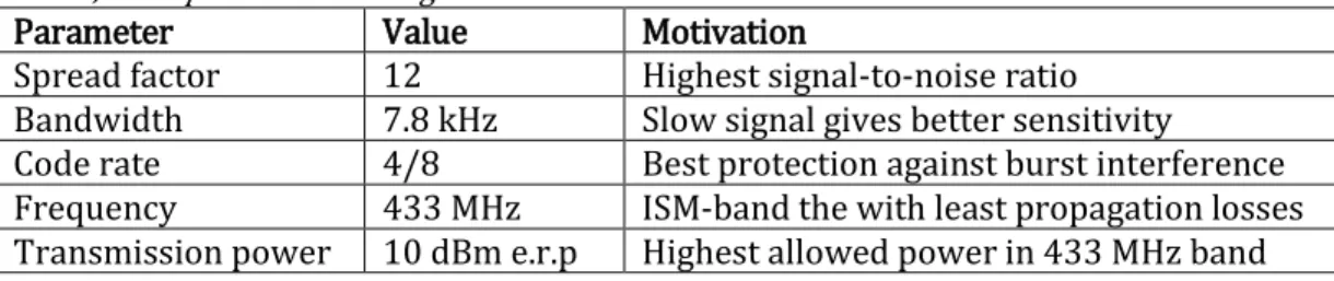
To finish the theoretical framework needed to determine the theoretical communication distance of the LoRa system, the configurable parameters of LoRa will now be presented based on descriptions given by Bor and Roedig [16]. This section will be concluded with a derivation of the sensitivity of the system based on the discussed parameters.
24 5.3.1 Spread factor
The spread factor (SF) is the ratio between the number of LoRa chirps (henceforth chips) that encodes a single data bit (symbol ), and is expressed by:
𝐶ℎ𝑖𝑝𝑠 𝑝𝑒𝑟 𝑠𝑦𝑚𝑏𝑜𝑙 = 2𝑆𝐹 (10)
Higher spread factor values increase the signal-to-noise ratio of the transmission, at the cost of increased air time and energy consumption per data packet. The spread factor can be chosen as an integer value between 7 and 12. Different spread factors are orthogonal to each other, which means that transmissions using different SF values don’t interfere with each other.
5.3.2 Bandwidth
LoRa is a spread spectrum modulation technique, where transmitted signals occupy a wider frequency band than the baseband of the data signal.
Figure 7, illustration of different bandwidths with the same center frequency
The bandwidth parameter determines how much the up and down chirps will be swept, and directly determines how fast chips will be sent. A bandwidth value of e.g. 125 kHz corresponds to chip rate of 125 kilo chirps per second.
LoRa BW values can take on discrete values between 7.8 kHz and 500 kHz in steps of doubling frequencies, with usual values being 125 kHz, 250 kHz and 500 kHz.
5.3.3 Code rate
LoRa employs forward error correction (FEC), where redundant data is encoded onto a data package to repair packages whose bits were corrupted due to burst interference.
Figure 8, illustration of packet with CR = 4/6
The code rate expresses the ratio between the number of payload bits and the combined payload and error correcting bits, taking on values of 4/5, 4/6, 4/7 or 4/8. Higher CR values offer more protection, but increases package size and as a consequence transmission air time.
25 5.3.4 Data rate and transmission air time
The rate at which payload is being transmitted is dependent on all three LoRa parameters BW, SF and CR. The Semtech “LoRa Modulation Basics” application note [25] derives the nominal data rate 𝑅𝑏 and expresses it as:
𝑅𝑏 = 𝑆𝐹 𝐶𝑅 (𝐵𝑊)2𝑆𝐹
= 𝑆𝐹 𝐶𝑅 𝐵𝑊
2𝑆𝐹 𝑏𝑖𝑡𝑠/𝑠𝑒𝑐
(11)
The data rate is proportional to the bandwidth, and inversely proportional to the code rate (which is always less than one) and the spread factor. As the data rate increases, the transmission time naturally decreases.
Determining the exact air time for a data packet depends on SF, BW and CR, as well as the number of chips in the preamble, packet header size and payload size. To reduce air time, an implicit header can be used where the header data is omitted if transmitter and receiver know its content a priori.
Air time is important when respecting duty cycle regulations. The longest air time for a packet with payload PL of 2 byte, default 6 preamble symbols and implicit header is obtained with SF =12, CR =4/8 and BW =7.8 kHz. That air time is calculated according to the LoRa Modem Design Guide [26].
Period length for a single symbol:
𝑇𝑠𝑦𝑚𝑏𝑜𝑙 = 2𝑆𝐹 𝐵𝑊 = 212 7.8 × 103 = 0.525 sec (12)
Period length of the packet preamble:
𝑇𝑝𝑟𝑒𝑎𝑚𝑏𝑙𝑒 = (𝑛𝑝𝑟𝑒𝑎𝑚𝑏𝑙𝑒+ 4.25)𝑇𝑠𝑦𝑚𝑏𝑜𝑙 = 10.25 × 0.525 = 5.381 𝑠𝑒𝑐 (13) Number of symbols 𝑆 for a payload with implicit header:
𝑆𝑝𝑎𝑦𝑙𝑜𝑎𝑑 = 8 + 𝑚𝑎𝑥 (⌈8 𝑃𝐿 − 4 𝑆𝐹 + 28 + 16 − 20 4 𝑆𝐹 ⌉ 4 𝐶𝑅, 0) (14) 𝑆𝑝𝑎𝑦𝑙𝑜𝑎𝑑 = 8 + 𝑚𝑎𝑥 (⌈ 8(2) − 4(12) + 28 + 16 − 20 4(12) ⌉ 4 4 8 ⁄ , 0) = 8 (15)
This then gives the period for the payload:
26 Finally, the period of the packet:
𝑇𝑝𝑎𝑐𝑘𝑒𝑡= 𝑇𝑝𝑟𝑒𝑎𝑚𝑏𝑙𝑒+ 𝑇𝑝𝑎𝑦𝑙𝑜𝑎𝑑 = 5.381 + 4.2 = 9.58 𝑠𝑒𝑐 (17) The most stringent duty cycle restriction was for the 868,7–869,2 MHz band with 0.1%, or 3.6 seconds per hour. The 9.58 second air time calculated above would violate the duty cycle limit for that frequency band.
For the 868–868,6 MHz and 433,05–434,04 MHz bands there is a duty cycle limit of 1% and 10 % respectively, or 36 seconds per hour and 360 seconds per hour. The air time of the calculated package therefor complies with requirements in both of these bands.
By doubling the bandwidth, the air times are halved. In order to be able to send packets more regularly, calculating the necessary bandwidth to still comply with regulation becomes simple; doubled bandwidth equals doubled allowed packets. 5.3.5 LoRa sensitivity
The sensitivity of the LoRa transceiver determines the maximum distance where communication can still function, and depends on the spread factor, bandwidth and code rate. According to the LoRa Modem Design Guide [26], the sensitivity 𝑆 is given by:
𝑆 [𝑑𝐵𝑚] = −174 + 10 log10𝐵𝑊 + 𝑁𝐹 + 𝑆𝑁𝑅 (18) where −174 + 10 log10𝐵𝑊 is the noise floor, NF is the noise figure of the receiver electronics and SNR the signal-to-noise ratio. According to the Lora Basics application note [25], the noise figure has the value 6 dB. This leaves the SNR as the unknown quantity to calculate.
The signal-to-noise ratio can be derived from the Shannon-Hartley theorem that expresses the theoretically highest possible data rate 𝐶 in a noisy channel:
𝐶 = 𝐵𝑊 log2(1 + 𝑆𝑁𝑅) (19)
If the signal-to-noise ratio is much smaller than 1, the value of the logarithm will be in the interval 0 to 1 and can be linearly approximated to:
𝐶 ≈ 𝐵𝑊 × 𝑆𝑁𝑅 ⇔ 𝑆𝑁𝑅 ≈ 𝐶 𝐵𝑊
(20)
The capacity 𝐶 for the LoRa transceiver was calculated earlier in Equation (11) as 𝑅𝑏.