Technical Report, December 2008
Reliability and Load Handling Problem in Internet
Service Provider’s Network
Master’s Thesis in Computer Network Engineering
Imran Pervaiz (800206-T052)
Mirza Kashif Abrar (790604-T079)
School of Information Science, Computer and Electrical Engineering Halmstad University
Reliability and Load Handling Problem in Internet
Service Provider’s Network
Master’s thesis in Computer Network Engineering
School of Information Science, Computer and Electrical Engineering Halmstad University
Box 823, S-301 18 Halmstad, Sweden
Preface
This thesis has been carried out as the final part of the Master of computer network engineering program that is attended at the Halmstad University in Sweden, autumn semester 2008.
This thesis has been supervised by Ms Olga Torstensson. We would like to thank her, for her help and support, while working on the thesis, valuable topics, suggestions and guidelines for the thesis that led to a successful conclusion.
Finally, we would like to thank our friends and families for their support thr oughout the master program.
Abstract
This thesis puts forward a new solution to provide the reliable network to the Internet Service Provider (ISP). This study mainly focuses on the ISPs network to provide reliability and the load balancing. It offers a guide line for the best reliable solution to the ISPs, individual organizations or other types of service providers which are engaged in providing reliable communications to their subscribers. These reliable services may be real time communications which include weather forecasts, tracking systems, online Internet protocol TV (IPTV) programs and many other ISPs services which are totally depend on the reliable network.
With the appearance and expansion of Internet subscribers all over the world, ISPs services are becoming more popular. The rapid increase of connection-demand and highly traffic network is the main reason behind the need to scale reliable network. To offer better solutions, a new theoretical and practical approach should be considered that can cover the reliable network.
The suggested network structure monitors the links, spreads the network traffic with multiple devices and takes a backup (redundant) link automatically when changes occur in the network topology. In order to support the redundancy, load balancing and reduce the failover time, the hot standby routing protocol (HSRP) is implemented on the suggested network. As we have analyzed that in any network, scalability bringing to raised the network traffic broadcast issue. Broadcast storms can be prevented by setting threshold values of traffic-filters. The threshold level helps to control broadcast traffic in networks.
With regard to suggested solutions, it is necessary to observe the limitations and advantages of the recommended reliable network structure. Therefore, this research will include the advantages and limitations of the techniques used to offer ISP services such as scalability, security and IPv6.
Keywords:
Internet Service Provider (ISP), Hot Standby Routing Protocol (HSRP), Virtual Local Area Network in Virtual Local Area Network (VLAN in VLAN (QinQ)).Table of Content
1 INTRODUCTION ... 9 1.1 PROBLEMDEFINITION... 9 1.2 MOTIVATION... 10 1.3 GOALS: ... 11 1.4 METHODOLOGY... 11 2 RELATED WORK ... 13 2.1 BACKGROUND... 132.2 REDUNDANCY ANDLOADBALANCING... 13
2.2.1 Spanning Tree Protocol (STP) ... 14
2.2.2 Rapid Spanning Tree Protocol (RSTP 802.1w) ... 15
2.2.3 HSRP (Hot Standby Routing Protocol)... 15
2.2.4 Gateway Load Balancing Protocol ... 16
2.3 COMPARISONS AMONGRSTP, HSRPANDGLBP ... 17
2.3.1 Hello Message ... 17 2.3.2 Failover Time ... 17 2.3.3 Port State ... 18 2.3.4 Optimization features ... 18 2.3.5 Port Role... 18 2.3.6 Router Roles ... 19 2.3.7 Load Balancing... 19 2.4 ETHERCHANNEL... 19
2.5 BROADCAST INCOMPUTERNETWORK... 20
2.5.1 Broadcast in Ethernet Network ... 20
2.5.2 Virtual local area network ... 21
3 ADVANTAGES/DISADVANTAGES OVER ISP NETWORK IN TERM OF SCALABILITY, SECURITY AND IPV6 ... 25
3.1 SCALABILITY... 25 3.1.1 Scalability Advantages... 25 3.1.2 Scalability Limitation ... 26 3.2 THE ROLE OFIPV6 ... 26 3.2.2 Advantages of IPv6 ... 27 3.2.3 IPv6 Limitation ... 27 3.3 SECURITY... 28 3.3.1 Security Advantages ... 28 3.3.2 Security limitation... 30 3.4 SUMMARY... 31 4 RESULTS ... 33 4.1 SCALABILITY... 33 4.1.1 Bandwidth... 34 4.1.2 IPv6 ... 35
4.2 REDUNDANCY ANDLOADBALANCING... 35
4.3 EXPERIMENT SET-UP WITH MULTIPLEHSRP GROUPS... 37 4.3.1 Equipments... 37 4.3.2 Implementation ... 37 4.4 Second Scenario ... 39 4.4.1 Equipments... 39 4.4.2 Implementation ... 39 4.5 BROADCASTSOLUTION... 41 4.5.1 Equipments... 42 4.5.2 Implementation ... 43 5 DISCUSSION... 45
5.1 RELIABLE ANDLOADBALANCING WITHHSRP ... 45
5.1.1 First Scenario ... 45 5.1.2 Second Scenario ... 46 5.2 BROADCASTSCENARIO... 47 6 CONCLUSION ... 49 6 REFERENCES... 51 7 APPENDIX... 53 7.1 ISP_A... 53 7.2 ISP_B... 57 7.3 ISP_SW1... 61 7.4 ISP_SW2... 63 7.5 ISP_ROUTER_A ... 66 7.6 ISP_ROUTER_B ... 70
List of Figures
Figure 1.1: Running ISP network infrastructure... 9
Figure 2.2: Example of VLAN ... 21
Figure 2.3: VLAN Broadcast Example... 22
Figure 2.4: Example of VLAN Broadcast with different Switches ... 22
Figure 2.5: Example of VLANs routing on Higher Layer Devices... 23
Figure 4.1: Old Structure ... 33
Figure 4.2: New suggested structure... 34
Figure 4.3: Ether Channel Link ... 35
Figure 4.4: IPv4 vs. IPv6 addresses ... 35
Figure 4.5: Load Sharing by Multilayer Switches with VLANs ... 36
Figure 4.6: link down of router A ... 38
Figure 4.7: Load Sharing by Routers with VLANs ... 40
Figure 4.8: Link down on Router A... 40
Figure: 4.9 Broadcast Storm control... 42
Figure 5.1 Link down of router B ... 46
Figure 5.2: Node 4 Touch the Threshold value ... 48
List of Tables
Table 4.1: Equipment for HSRP ... 37Table 4.2: Second Scenario Equipment ... 39
Table 4.3: Equipment for Broadcast ... 42
Table 4.4: Threshold level 0.00% ... 43
Table 4.5: Threshold level value 0.009% ... 43
Table 4.6: Threshold level value 0.01% ... 44
1 Introduction
Today users want higher bandwidth Internet connection without the extra burden in terms of expenses and advanced modems. The Internet service providers (ISPs) have had a great impact for delivering high bandwidth Internet connections to the subscribers. The ISP is a way for users to connect to the Internet services. The ISP enters into business arrangements for connectivity with other service providers to make sure that the customer’s data is able to move smoothly among the various parts of the Internet. The average rates of customers are connected to the ISP network through dial-up modem or broadband connection. For convenient services to the Internet subscribers, ISP maintains connections with the efficient use of network devices and bandwidths. ISP provides the capable communication to connecting the remotely offices.
1.1 Problem Definition
Redundancy and load balancing are crucial issues facing anyone implementing high-throughput connections to the Internet. The demand for the Internet application services is increasing. It is vital that a better communication framework is implemented, which resolves present problems and also give the reliable solution to the ISPs network.
In the above figure 1.1 ISP network, problem is based on reliability and load balancing. Currently this problem has been covered by Rapid spanning tree protocol (RSTP); but still it does not provide the load balancing solution. Furthermore, RSTP does not provide the fast re-convergence when network topology has changed occur. Thus any real time packet loss during route re-convergence cannot be recovered and this loss more or less depends upon the selection of protocol in the available network topology.
Load balancing is the technique to spread the network traffic for the optimal network resource utilization. This uses a single link increase the reliability of network instead of using multiple devices and links for load balancing. For example, if one link fails then an alternative path will take over the network traffic quickly in order to provide the fastest and most reliable packet forwarding. If the network does not provide any redundancy link, the entire network may fail due to a single link failure. Redundancy is defined as a duplication of components or devices that allows continued functionality despite the failure of an individual component. In the suggested network, redundancy and load balancing increases the reliability and reduce the downtime that is caused by a single point of failure. Currently this ISP network structure has redundancy and load balancing problems.
The above scenario demonstrates another issue relating to the ISP network, broadcast traffic? Virtual local area networks (VLANs) are configured in the ISP networks. Generally, the VLANs are further divided into multiple VLANs. The result is a broadcast storm, which may occur when a large number of broadcast packets are received at a port. The forwarding of these packets can slow down the network or create a time out limitation for the packets. Moreover, the broadcast traffic in a stable network can result in the collapse the ISP network traffic, which may raise the packet loss, deadlock and etc issues.
1.2 Motivation
This research thesis describes the advantages and limitations of scalability, security, expandability to IPv6 in ISP network. In the first part we review these salient features in detail.
Once the ISP network is enlarged by offering more connections to subscribers, it is important to maintain the services. In consideration to this issue, hot standby routing protocol (HSRP) is implemented to fulfill the
requirements of redundancy and load balancing. The HSRP provides a mechanism for determining active and standby routers. If an active router fails, a standby router can take over network traffic without any interruption in the host’s connectivity. It fulfills the goal of redundancy and load balancing with best features (priority, preemption etc) by hiding failures from the end devices. HSRP also provide a fast re-converge, when network topology changes occur. HSRP is supported the IPv6 for scalable ISP network solution.
The expansion of broadcast networking has raised many issues in the network industry. For example, the numbers of subscribes are increasing every day, which may create problems for network scalability. It has negative impact on the network, so threshold level setting are been used to control the broadcast storming for reliable ISP network.
1.3 Goals:
This thesis reviews and provides valid solutions for the following issues: analyzing the advantages and limitations of the suggested ISP network
in term of scalability, security and expansion with IPv6
understanding of redundancy and load balancing methods, and discussing the solutions for reliability and load balancing to the ISP network
discuss and provide efficient solution for reducing the broadcast traffic in such an ISP network
1.4 Methodology
This research narrates the current problems in ISP network and provides a suggestion to cover the addressed issues with the help of some practical implementations. This study is based on IEEE, IETF, CCIE books and Cisco's research material, which gives valid solutions.
Cisco's equipments has been used for the implementation in our scenarios. The reason behind the choice of this equipment, which is available in the Lab and the best practical solution will be put forward in this thesis.
2 Related Work
2.1 Background
In the ISP network, only one link is connected to the Internet subscribers. Currently, rapid spanning tree protocol (RSTP) is used in the ISP network. The RSTP takes 15 seconds to re-converge the network. It does not support the load balancing in the network. VLANs are configured for the separation of the Internet services. The open shortest path first (OSPF) routing protocol has been used in ISP network for communication of devices.
The main problem in the above ISP network infrastructure, is that it does not support the reliable network topology. The re-convergence time is also very high for the failover network. In addition to the redundancy, the RSTP protocol does not support the load balancing. By increasing the Internet subscribers and redundancy, the broadcast is also increased. Thus, the broadcast is one of the issues in the ISPs network infrastructure.
2.2 Redundancy and Load Balancing
Most of companies require network infrastructure without interruption of the services. Redundant link is one of technique to achieve the backup link, if master link fails. Redundancy is good approach to solve the fault tolerance issues in the network. One of the keys to make redundancy work for fault-tolerance problems is the mechanism for switching to the backup. The network redundancy should be the primary consideration for automated fault recovery. It is clearly an important way of improving reliability in a network, particularly reliability against failures [1].
The load balancing is a technique that uses to spread work between two or more devices, network links, CPUs, or other resources. It is used to achieve optimal resource utilization, and minimizing the response time. Achieving the load balancing with multiple devices, instead of a single component, network reliability is increased through redundancy. Redundancy may not resolve congestion problems and sophisticated load balancing schemes may be called for. The load-balancing and redundancy manages traffic very efficiently as well as redundant link and response time to improved along the cost-effective load.
There are two approaches which can be used to support the load balancing such as software based load balancing and hardware based load balancing. In the hardware load-balancing, devices use numerous factors to make a decision relating to how to route the traffic. The device will examine the traffic or by pass the traffic to other devices to process and optimize the load across the traffic.
Redundancy and Load balancing provides optimized resources and reliability. Some protocols are loop free like spanning tree protocol (STP), rapid spanning tree protocol (RSTP) and these do not provide the load balancing [1]. There are different protocols which provide the redundancy and load-balancing in the network. There are hot standby routing protocols (HSRP), virtual redundancy routing protocols (VRRP) and gateway load balancing protocols (GLBP), which provide the best features.
We review the different protocols and compare them later on, to decide which protocol is efficient for providing redundancy, load-balancing and minimizing the failover time.
2.2.1 Spanning Tree Protocol (STP)
A bridge loop occurs when there is no time-to-live mechanism existing to manage the redundant paths and stop the frame from circulating endlessly. A loop free network can be achieved manually by shutting down the redundant links between two or more bridges. However, this leaves no redundancy in the network and requires manual intervention in the event of a link failure. Spanning tree protocol (STP) is a link management protocol. It provides a loop free network. If there are alternate links to a destination on a switch then only one link is responsible for forwarding the traffic. The spanning tree algorithm runs on a switch to activate or block redundant links. The spanning tree algorithm determines any redundant path. If it is there, it chooses which path will be utilized to forward frames and which path to be blocked.
The blocked link cannot forward traffic. However, the interface in blocking mode continues to listen, for changes in network topology. If a link or interface fails, the spanning tree process begins again. The STP typically
takes between 30 to 60 seconds to “converge” [1]. Convergence occurs when switches and bridges define a stable tree and traffic can pass freely around the network. For many networks, convergence time of 30 to 60 seconds is simply too high. Thus, it is required to enhance the STP, to achieve faster convergence times for redundant link.
2.2.2 Rapid Spanning Tree Protocol (RSTP 802.1w)
Rapid spanning tree protocol (RSTP) is the enhancement of the spanning tree protocol (STP) 802.1D. RSTP helps with convergence issues that plague legacy STP. RSTP has additional features similar to UplinkFast and BackboneFast that offer better recovery. RSTP requires a full-duplex point-to-point connection between adjacent switches to achieve fast convergence. RSTP speeds the recalculation of the spanning tree when the layer 2 network topology changes. The STP takes 30 to 50 seconds to re-converge the network, but the RSTP protocol reduces it [2]. RSTP is designed to provide faster recovery convergence time from topology changes. RSTP adds a new port designation for the recovery of the failover network. This alternate port acts as a backup port to the root port, if active link fails.
2.2.2.1 Converge Time
Only three states are lying in the RSTP: discarding, learning and forwarding. RSTP skip the listening state and blocking state. RSTP reduces the re-convergence network failure time by skipping the time-consuming listening and learning stages. RSTP is backward compatible with the STP. In the case of STP BPDU receives, the STP standard should work in conjunction with the switch port. The result increases the recovery time of the network because the switch works with STP states (five states). Therefore, in the RSTP the re-converge time is shorter because of forward delay only, which is equal to 15 seconds. This convergence time is also very high for a large network [2].
2.2.3 HSRP (Hot Standby Routing Protocol)
Hot standby routing protocol (HSRP) provides a mechanism to support non-disrupting failover network. It allows the devices to use a single virtual default gateway to transmit the traffic. HSRP allows one router to resume the function of a second router if the first router fails [3]. HSRP is useful for
critical networks that need a failover router for network reach ability. HSRP uses a priority scheme to determine the default active router. If the router is configured with a higher priority, it acts as an active router. By sharing an IP address and a MAC (Layer 2) address, multiple routers can act as a single “virtual” router and this virtual router can be configured as the default gateway. Frames are sent to the virtual router’s address and processed with virtual router group, because the HSRP works in the group and forwards to the destination address.
2.2.3.1 HSRP Group
In HSRP, a set of routers work in concert to present the illusion of a single virtual router to the hosts on the LAN. The set is known as an HSRP group or a standby group. In the HSRP each router is assigned a specific role within the group because an HSRP group consists of the following: Active Router, Standby router, Virtual router, other router. In the HSRP standby group, the set of routers are jointly emulating a virtual router.
It is possible to share some traffic with the standby router. HSRP offers different features including groups and priority [3]. It is possible to achieve the load balancing by applying the HSRP features such as priority on each different VLAN or by the standby groups on different routers. HSRP provides redundancy very efficiently. It optimizes the traffic and reduces the re-convergence time in the network [4].
2.2.4 Gateway Load Balancing Protocol
Gateway load balancing protocol (GLBP) is a successor of HSRP. It is similar to HSRP; however GLBP is able to use multiple physical gateways at the same time. GLBP allows the automatic selection, simultaneous use of multiple gateways, and automatic failover between those gateways. Multiple routers share the load of frames that, from a client perspective, are sent to a single default gateway address. With GLBP, resources can be fully utilized without any burden.
GLBP has one active virtual gateway (AVG) router as a master router and other routers are actual virtual forwarding (AVF). The GLBP uses full resources without the CPU overhead on one router. GLBP allows automatic
selection for AVG and AVF by using the priority. If the priority is same, the MAC addresses are used for the selection of the AVG and AVF routers. GLBP also uses multiple gateways and automatic failover for gateways. As if we compare the re-converge time it is same as the HSRP, it holds 10 seconds for network re-converge, then the higher priority AVF act as AVG. GLBP provide one extra feature that is load balancing. However, the problem with GLBP is that it supports only specific Cisco catalyst switches [5].
2.3 Comparisons among RSTP, HSRP and GLBP
A network with high availability provides alternative means by which all infrastructure paths and key servers can be accessed at all times. RSTP, HSRP and GLBP have software features that can be configured to provide redundancy to the network host. These protocols provide immediate or link-specific failover and a recovery mechanism. Here a major issue arises, as to which protocol is best to provide the high availability with load sharing. If we compare these protocols (RSTP, HSRP and GLBP), it can be agreed that HSRP offers intrinsic features for providing redundancy and load sharing.
Take a look at HSRP, GLBP and RSTP main characteristics. Some states are the same but some HSRP states are advantageous over RSTP and GLBP.
2.3.1 Hello Message
With the redundant link, a set of router works by sharing an IP address and a MAC (layer 2) address. Two or more routers act as a single router [4]. For identifying the presence of redundant link or device the ‘hello’ message is used. The hello message generates bridge protocol data units (BPDU) every three seconds for a keepalive mechanism. The bridges send and receive keepalive messages in HSRP between bridges using the multicast address 224.0.0.2 [4].
2.3.2 Failover Time
The aim of RSTP, HSRP and GLBP is to maintain redundant connections which are reactivated only when topology changes occur. However, they differ in the time it takes them to re-converge after a topology change. The
convergence of the RSTP is three consecutive hello messages. The default hello's time is three seconds [2]. In order to achieve the fast re-convergence time, the behavior of the RSTP had to be changed. The HSRP provides the facility to adjust the HSRP hello timers. This timer adjustment tunes the performance of HSRP. HSRP hello and hold timers can be adjusted to millisecond values [9]. With HSRP and GLBP, the hello's value can set from the range of one to 255 [4].
2.3.3 Port State
RSTP provide rapid convergence when a link failure or during re-establishing. RSTP has three basic operations of a switch port: discarding, learning and forwarding [2]. In all port states, BPDU frames are processed. The discarding and learning states are seen in both stable active topology and during the synchronization and change stages. The forwarding state is seen in stable active topology only, because the data frames forwarding occurs only after a proposal and agreement of process. Only three states are performed action in RSTP for stable network [2]. The router exists in one of the states for the stable network. All HSRP routers in the group perform transitions through all states. For example, if there are three routers in the group, all routers perform all states and become active and standby router. The keepalive time is same in RSTP and HSRP but the states are different. HSRP performs well and provides better performance.
2.3.4 Optimization features
HSRP and GLBP offers optimizing options to make it possible to allow the network optimizations. RSTP does not provide these kinds of optimization features and the HSRP and GLBP tracking options. The tracking options monitor interface condition such as line-protocol and IP routing. The other feature is priority value. The priority value in a standby group in HSRP is allowing influencing the active and standby router selection [4]. The Preemption option provides the facility to active router become active after re-establishing the link (if active router fails) [4]. The RSTP does not provide optimization features.
2.3.5 Port Role
The Port role is the way to handle the data frames and define the ultimate purpose of a switch port. Port roles are able to transition independently. The
additional port allows the RSTP to define a standby switch port before a failure or topology change. The designated port forwards the data frames. If it designated port is failure then alternative port moves to the forwarding state [6].
2.3.6 Router Roles
HSRP has one active and standby router and more than one router perform as a listen state [4]. However if we compare with GLBP, the protocol has one active virtual gateway (AVG) router with the highest priority among all routers. For the backup or standby, up to four active virtual forwarding (AVG) routers are in GLBP [5]. HSRP and GLBP have major advantages for the optimization of load sharing. If we compare with the port roles in RSTP, the HSRP has active and standby routers. This HSRP features offers sufficient solution to enable redundancy and load balancing.
2.3.7 Load Balancing
In order to share the network traffic, load balancing is required. One of the drawbacks of the RSTP is load balancing; RSTP does not provide the load balancing [2]. In other hand, HSRP facilitates the load balance in order to optimize the network traffic. To facilitate load sharing, a single router may be a member of multiple HSRP groups in the network. Multiple HSRP standby groups can enable load sharing. There can be up to 255 HSRP standby groups on any LAN [7]. The GLBP is a host dependent; each client will always have the same virtual MAC [5].
Although, the comparison shows that the HSRP has efficient features for providing the redundancy and load-balancing. The GLBP is supported only by specific Cisco’s devices that are not enough for network solution. Consequently, the HSRP is the efficient protocol for providing the redundancy and the load balancing as well as for scalable network because HSRP supports the IPv6. The IPv6 provides a more robust router discovery through its neighbour discovery protocol (NDP) [8].
2.4 Etherchannel
Etherchannel provides the higher bandwidth with lower cost overheads. Etherchannel allows the two, four or eight physical Ethernet links between
the two devices to create one logical Ethernet link for providing high-speed and fault-tolerance links.
The Etherchannel allows these features and has the following advantages: It allows a very high bandwidth logical link
It configures only on the logical interface
It provides the Load balancing among the physical links involved [9] There are two (PAgP or LACP) protocols that are used to configure channels between devices. Once a channel is created, load balancing can be used by the connected devices to utilize all the ports in the channel.
The Etherchannel has had some restrictions:
In an Etherchannel interfaces must be configured identically: speed, duplexing and VLAN.
The Etherchannel can be set up to eight interfaces bundled [9]
2.5 Broadcast in Computer Network
In any network infrastructure bandwidth plays a major role. Especially in the ISP network, appropriate utilization of bandwidth provides the efficient speed to the Internet subscribers. However, increasing the subscriber brings the broadcast traffic into the network. This is one issue described in the report and provides the efficient solution to solve the broadcast traffic in such a ISP network. In computer networks, broadcasting refers to transmitting a packet that will be received by every device in the network. A broadcast may occur when two devices (e.g. clients and servers) come to identify themselves. Sometimes, network devices continually announce their presence and some unnecessary packets are generated. A broadcast is mostly confined to local area network technologies, most notably Ethernet and Token Ring.
2.5.1 Broadcast in Ethernet Network
Ethernet is a dominant local area network (LAN) technology. In the Ethernet, the hosts are connected to a network through a single shared medium. The broadcast in Ethernet network happens when the redundant switched topology is present and there exists a loop in the Ethernet topology (where more than 2 links exist between switches) [10]. As a broadcast is
forwarded by switches on every port in the same domain, the two switches also broadcast each other’s broadcasts; as a result a loop is created. In the above ISP network, for dividing the single broadcast domain into multiple local area network broadcast, the virtual local area networks (VLAN’s) are configured. The VLAN divides the network broadcast into multiple broadcast domains.
2.5.2 Virtual local area network
A VLAN is a virtual local area network that extends beyond a single traditional LAN to a group of LAN segments. It is a mechanism to allow network administrators to create logical broadcast domains that can span across a single switch or multiple switches, regardless of physical proximity. The VLANs reduce the broadcast domain size or to allow multiple groups or users to be logically grouped [11].
Network operations require broadcasts to function properly, but huge broadcast traffic may cause a serious problem in the network. To minimize the negative impact of large broadcast domain, VLANs divide the huge broadcast domain into multiple broadcast domains. VLAN (Virtual LAN) provides the facility to create multiple LANs in a single switch device or LAN’s without adding new hardware devices [11].
Figure 2.2: Example of VLAN
Physically, after configuring the VLANs, all hosts reside on different VLANs as shown in figure 2.2. Switch is configured with VLANs. The
switch will forward a broadcast only to those devices or hosts in the same VLAN as the host that originated. For example in the figure 2.3 we have two VLANs which exist in a switch. These VLANs split the network into two broadcast domain networks.
Figure 2.3: VLAN Broadcast Example
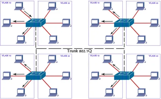
In figure 2.4 we have two or more switches in the network, where all switches have VLANs. Same VLANs can coordinate with other VLANs with a trunk port and the trunk is responsible for carrying the whole VLANs traffic from one switch device to another [11].
For communication with different VLANs, this is essential to implement layer 3 device (router or layer 3 switches). Trunk carries all VLAN traffic and communicates with other VLANs using the network layer device as shown in figure 2.5. If any VLAN host wants to communicate with different VLAN host, it is able to communicate through routing.
3 Advantages/disadvantages over ISP network in term
of Scalability, Security and IPv6
This study describes the advantages and limitations in term of scalability, security and the role of IPv6 over ISP network.
3.1 Scalability
Scalability is the ability to continue the functions well in terms of expanding the size of networks to meet a subscriber’s need. Generally, it is the ability to increase the existing system without disrupting the current subscriber to meet the business needs. For rapidly increasing ISP subscribers, it is needed to enlarge the ISP network service.
3.1.1 Scalability Advantages
A scalable network provides an economical means of expanding an existing network to expeditiously meet future demands with minimal interruption in service availability caused by expansion process.
The global demand for data services has grown at a remarkable rate in recent years. The increase in demand is likely to grow at an even faster pace in the future because of advances in multimedia services. Network scalability becomes an important consideration for Internet service providers.
The overall system capacity has to be made expandable in terms of the number of subscribers supported, data rate, and geographic coverage. The persistent demand for enhancement in data services is becoming an important driving force for network expansion and deployment. Consequently, the network is capable of supporting new services when they become available.
The scalability of the network allows providers to differentiate their portfolios and to customize, bundle, and offer ever more sophisticated services that will improve customer retention and create more stabilized revenue streams.
The ISP network scalability offers high-speed bandwidth for Internet connection to each subscriber. It can provide integrated applications such as voice, video, data, real-time applications, peer-to-peer file sharing, interactive gaming and voice over IP.
Scalable network offer a reliability and availability of users to the network outages and failures. The scalable network solution provides the good network response to the subscribers because users expect network resources to respond quickly. Consequently, networks must be configured to meet the needs of all applications, delay-sensitive applications [12].
Scalable network solution makes the network efficient, especially in increasing bandwidth. Because an efficient network does not waste the bandwidth, it is possible by efficient devices and infrastructure, for example routers should prevent unnecessary traffic from traversing the network [12].
3.1.2 Scalability Limitation
With the multiple advantageous, scalability has some limitations or drawbacks,
Complex network design can become a limit to scale the network. Because, scalability is allow for growth in a network. But growth can be difficult to achieve without redesign the network.
Redesigning the network may be required to change the devices. These devices may be important and costly; the ISP may not be able to afford these devices at a given time, as well as more technical staffs are required [12].
3.2 The role of IPv6
IPv6 is designed to enable ISP to meet the challenges with the exponential growth of the Internet subscribers. IPv6 provides new services to their customers. IPv6 combines expanded addressing with more efficient and feature-rich headers to meet the demands for a scalable network in the future. IPv6 is a new version of Internet protocol and intended as a successor to IPv4 protocol at layer 3 [13]. It is a next-generation Internet protocol and the standardized by the IETF. IPv6 is specially designed for the problem solving in IPv4 address limitation because the growth of Internet
subscribers, especially in the greatly populated countries. For the limit of addresses in IPv4, the Network Address Translation (NAT) is used. Approximately one IPv4 address is used for 15 users by using NAT but IPv6 solves this problem with greater addresses with approximately 15 addresses per user [13].
3.2.2 Advantages of IPv6
IPv6 provides an ideal environment to develop peer-to-peer applications. It requires considerable number of Internet protocol addresses.
The IPv6 addressing of space is sufficient to allow organizations to define a single prefix for the entire network. There is an efficient and scalable routing table for aggregation of customer prefix results. It is also the scalable solution to expand the network functions. Today most of ISP organizations are used IPv6 for reducing the address space [14].
IPv6 allows plug and play services. It provides high performance solutions for configuring terminals and basic mechanisms to manage IP connectivity [15]. IPv6 reduced the broadcasts using the neighbor discovery to perform a similar function during the auto-configuration process.
Enabling multiple functions such as end-to-end communications, security and mobility are considerably simpler and widely deployed in view of the end-user benefits offered by the built-in mobility in IPv6.
IPv6 allows multiple globally routable addresses per access network. IPv6 provides end-to-end communication without using network address translation (NAT) devices [14].
It is easy to configure the IPv6to4 tunnels without the need to obtain IPv6 address space.
3.2.3 IPv6 Limitation
IPv6 to IPv4 tunnels have limitations, because in broadband technology, subscribers want to create a private connection with remote office. Whenever the IPv4 address changes, the IPv6 addresses also changes. The communication with users of regular IPv6 address often incurs detours
through remote relays in the absence of relays closer by. The problem with relay services is that it is not always a reliable and the flow of traffic is generally asymmetric (packets flow bidirectional with and follows different paths through the network) [17].
IPv6 network has some limitations that DOCSIS 2.0 and prior specification do not allow the smooth implementation of a native IPv6 transport [15]. Another disadvantage of using IPv6 is that header translation of Internet protocol address. Because usually only the headers are translated, if the payload encapsulate the header (for example in VoIP applications), it is not possible to translate the header, because the translators do not know inside the header [14][18].
Legacy devices at the residential network do not support IPv6 [18]. The IPv6 has a lack of support from legacy applications that are run at the subscriber end. Consequently, the subscriber should purchase new device for the support of IPv6 protocol. The cost of new hardware spending but the subscribers don’t want extra pay for IPv6 [14].
3.3 Security
Security is the procedure of protecting the network from unauthorized users to use the network resources. These intruders can be stopped and blocked for accessing the network. Layer 2 security has some important aspects and these facts can play a major role in the network for reducing the intruders. These are port security, private VLAN, dynamic host configuration protocol (DHCP) snooping, dynamic address resolution protocol (ARP) inspection, enable root guard, disable Cisco discovery protocol (CDP), use of SSHv2, implementing firewall over edge network, using intrusion detection (IDS) and prevention security (IPS) etc [20].
3.3.1 Security Advantages
Authentication is required for each subscriber; it ensures that only authorized senders and devices enter the network. Authentication security discourages unauthorized users from accessing the network.
The ISP ensures the subscribers for full integrity of data. Since the users do not know where the data has traveled and who has seen or handled the data. That data has sent or received while the traveling across the network. There is always possibility that the data has been modified. Data integrity guarantees that no altering occurs to data, while it travels between the source and destination [19].
ATM-based architectures also provide one or more virtual circuits dedicated to each customer over the physical connection. This separate virtual circuit makes unauthorized monitoring or access to communications more difficult. Furthermore, the security and management by the creation of virtual circuit connection specific paths is established between a service provider and subscribers. They protect any remote configuration of equipment at the user’s premises.
One proposal for secure communication between the ISP and the subscriber is a multi-service capable model is installed at customer premises. The customer’s premises equipment integrated into the security framework. When there is communication between the subscriber and the service provider, the customer premises equipment (CPE) auto-configures authentication on behalf of the subscriber. The service provider assigns a public key certificate to the subscriber during the customer premises equipment installation [21].
Network monitoring is an ongoing concern for any significant ISP network. It is to observe the traffic flow and efficiency for subscribers. Intrusion detection systems (IDS) act merely as alarms, indicating the possibility of a breach associated with a specific set of subscriber activities [19].
Intrusion prevention system (IPS) sends requests to a host that is initiated by applications. These requests are either allowed or rejected according to the particular application security policy that is in effect. For example, a host receives a potentially destructive file system manipulation request, or a request to do something that is potentially dangerous on the network. The IPS stops the request from being carried out. In fact, in many respects IPS provides an almost ideal opportunity to the subscribers for denying suspicious data transfers [6].
Denial of service (DoS) attacks can exploit a known vulnerability in a specific application or operating system, or they may attack features in specific protocols or services. In this form of attack, the attacker is attempting to deny authorized users to access either to specific information or to the computer system or network itself. The purpose of such an attack can be to simply prevent access to the target system, or the attack can be used in conjunction with other actions in order to gain unauthorized access to a computer or network [19].
3.3.2 Security limitation
These issues present challenges for server side’s security including remote authorizing, transaction security, and server protection from subscriber side. Some ports (e.g. HTTP, FTP) cannot be blocked; if these ports are blocked then it can block the web services also. These Internet services might be important for the subscribers. The security threat is posed at the physical layer; however physical devices such as hubs and repeaters become the entry for attackers.
The foreign computers and network equipments in the ISP network can adversely affect the network. These cases occur when new systems are configured with an already IP address. Both of systems attempting the same IP address will fight for that address. This causes network confusion and the loss of service especially in the case of gateway system or servers. A miss-configured network causes an inability to communicate with other systems on the network, and the results in abnormal ISP network performance.
The ISPs guarantee the security of the devices that perform security and where policy is maintained. Security policy plays a key role in the deployment of secure networks. If the policy is compromised, their security can be compromised to the attacker. For example, the hacker can just change the policy to use DES instead of 3DES and encryption can be null. In this state, even the packets are being secured; these packets can be less powerful encryption algorithm [20].
The ISP’s edge devices might not be prevent from snooping and snooping open up a whole lot of issues. The packets can capture before the packets are
encrypted and it is possible for the rouge person to capture the contents in clear text or modify the clear text [20].
Those users who are always on the Internet (e.g DSL subscribers) without protection are precisely the targets that hackers are looking for. They can scan ports, stage distributed denial of service attacks and upload worms, viruses and Trojan horses at any time and at very high speed [19].
3.4 Summary
This chapter discussed the scalable network characteristics, including the advantages and limitations of ISP network. It is advantageous for the scalable network that provides reliability and availability of services, efficient and accessible but secure service. Good design is only the key to provide the scalable network because it allows for growth of network easily. For example, if the organization wants to add more devices the network adopts it with small modifications. On the other hand, poor and complex network design and an outdated protocol are not able to scaling the network. The IPv4 has addressed limitation and some services are very hard to handle by NAT or PAT. IPv4 uses a broadcast address. However as compared to implementing the IPv6 in ISP network, it offers better scope in the long-run for providing the always-on high speed Internet service. IPv6 is easy to configure and avoids the NAT (network address translation) service because of large IP addresses which are available. The main reason to deploy the IPv6 is the annual growth rate of the Internet subscribers. In the case of IPv4 it must use NAT. However IPv6 provides the large address space, so it does not need to implement the NAT. Another advantage is that IPv6 does not use broadcast address. IPv6 replaces broadcast address with multicast addresses. If we compare with IPv4 to the IPv6 in terms of broadcasting, IPv4 uses broadcasting and the results may cause several problems. The broadcasting generates a number of interruptions on the network, this problem can suspend an entire network and subscribers can be unreachable for connection with the Internet. IPv6 supports auto-configuration mechanisms. It is possible that the hosts can use stateless auto-configuration or state full DHCPv6-based configuration for the IPv6 address to the edge router. IPv6 provides greater flexibility and greater redundancy where multi-homing
exists [8]. It is efficient approach to support the large number of Internet subscribers in the form of auto-configurations, addresses, multicasting, etc. The security is the vital aspect of any network infrastructure. All users must be authenticated who want to access the network resources. Using the special identity, network arranges the resources to be allocated to the subscribers. One time password is a good authentication to secure the connectivity of all subscribers. At the provider edge the DMZ (Demilitarized Zone) area is defined for the security purposes and only authorized subscribers are able to enter in the network. The subscriber allows services for a valid period of time.
In implementing the public key infrastructure (PKI) and digital signatures (DS) for the data integrity and the validation of authentication, the exchange certificate (EC) can be applied. Whenever a new subscriber is enrolled for accessing the network resources, the key exchange mechanism is implemented automatically. Users indicate which services they want to use. Only specific services are allowed to the subscribers. Security plays a major role especially in the field of E-commerce.
4 Results
4.1 Scalability
By evaluating some results contained in research papers and the results from practical work, we can be provided with better solutions for the ISP network. Further detail will describe how to solve scalability problem and offer good bandwidth. Scaling the network has issues that can be improved with some techniques. The improvement in the structure results in improvements in the bandwidth and scalability with IPv6. In the given scenario (old structure) there were disadvantages such as single link without a backup link for failure.
Figure 4.1: Old Structure
Currently we have suggested the improvement in given structures, which will provide high bandwidth, reliability and extendibility with IPv6.
Figure 4.2: New suggested structure
4.1.1 Bandwidth
Bandwidth refers to capacity or available channels, which means the channel capacity of logical or physical communication path in a digital communication system [16].
In any real time network Ethernet switches, the effective bandwidth of the segment can be increased by reducing the contention for the available bandwidth resources. There are two ways to increase the network bandwidth. One way is to reduce the affecting factor (cable attenuation, bridge tap, etc) in the media. This method can save bandwidth and be utilized in the efficient way. The second way is to increase the amount of bandwidth available by changing network media. For example, if we replace the 4 Mbps with 16 Mbps link, it will increase the available bandwidth by a factor of four.
With regard to our research, we are suggesting above solutions to increase the network bandwidth. Both of them can be implemented based on different situations with different requirements. In one suggested solution, ether channel can increase bandwidth using a double bandwidth. Usually bandwidth depends on switches. When create a groups of ether channel, it provides more reliability with two Ethernet link and consider one single link or channel as show in figure 4.3.
Figure 4.3: Ether Channel Link
4.1.2 IPv6
The second method implements the IPv6 in the ISP network. The main reason behind the IPv6 over ISP is the number of rapidly increasing Internet subscribers especially in highly-populated countries. With IPv6, one is not required to configure dynamic non-published local IP addresses, the gateway address, the sub-network mask, or any other parameters. The equipment, when plugged into the network, automatically obtains all requisite configuration data [17]. These IPv6 features provide the efficient solution for a scalable ISP network.
Figure 4.4: IPv4 vs. IPv6 addresses
The network with high availability means alternative paths by which all infrastructure and key servers can obtain access at all times. This solution is based on hot standby routing protocols (HSRP) that provides load balancing and redundancy. It solves the problem of backup and network availability with different routes that rapid spanning tree do not provide. We find some results through practical implementation which shows the optimization features of HSRP.
4.2.1 Optimize the Network with multiple VLANs & Groups
In a single HSRP standby group, only one router (the active router) is responsible for forwarding all the packets. While the standby router is not forwarding any packets, the standby router will be an idle state. To facilitate the load sharing, a single router may be a member of multiple HSRP standby groups in a network [4]. One HSRP standby group is responsible for forwarding the traffic of one standby group. The other router is responsible to forward the traffic of other HSRP standby group. Each HSRP standby group emulates a single virtual router. This report provides the extensive availability of the network if a device is fails.
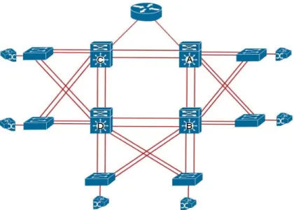
Figure 4.5: Load Sharing by Multilayer Switches with VLANs
In the figure 4.5 loads sharing with VLANs and HSRP standby group, four VLANs and two HSRP standby groups are configured. By configuring the HSRP standby groups, users can eliminate situations in which a single point of failure causes traffic interruptions [4]. The HSRP feature provides improvement in overall networking resilience by providing load balancing
and redundancy capabilities between VLANs. The multiple HSRP groups are configured in the network to facilitate the load sharing [4].
It may be possible that all the routers are same group, one router works as active router and all others are standby routers. With HSRP, only one active router is responsible for forward all traffic, others standby routers are idle. We implement the best feature (priority) for share the traffic. The priority feature of HSRP provides load sharing with standby routers.
Consequently, we experiment to set the four HSRP standby groups with four VLANs are configured on each switch. Once this has been observed, we can ask whether there has been any problem with the redundancy and the load-balancing.
4.3 Experiment set-up with multiple HSRP Groups
4.3.1 Equipments
For implementation, we have used Cisco’s devices (One router, four multilayer and six layer 2 switches). For doubling the link we have used Etherchannel link for redundancy and increasing the bandwidth.
Table 4.1: Equipment for HSRP
Cisco’s Devices Description Quantity
Router 2800 Series 1
Multilayer Switches (Layer 3)
3560 Series 4
Layer 2 Switches 2960 Series 6
Etherchannel Cat 5 (Double Cross
Cable)
16
4.3.2 Implementation
We have confirmed the feasibility of the proposed network infrastructure, we used four switches each (Multilayer and layer 2). For one HSRP standby group, one router acts as an active router and other router works as standby router for same group. In the other HSRP standby groups, one router works as active router that router is already work as standby router in a group.
In terms of HSRP optimization and redundancy, all routers (A, B, C and D) are members of HSRP groups (1, 2, 3 and 4). Each standby group has its own active and standby routers. During the election process, the router with the highest priority in an HSRP group becomes the active router. In this scenario we set the highest priority (150) of Router A to become the active forwarding router of HSRP group 1 and for the standby router set the default priority (100) for group 2. Router B is the active forwarding router for HSRP group 2 and the standby router for HSRP group 1. The same router C is the active forwarding router for HSRP group 3 and the standby router for group 4. Router D is the active forwarding router for HSRP group 4 and the standby router for HSRP group 3.
After configuring the multiple HSRP groups, Etherchannels are configured. Etherchannel provide a substantially higher bandwidth with lower cost overheads. Etherchannel bond the two, four, or eight ports to develop connection with redundancy. Etherchannel provides load balances among the physical links and provides automatic failover. We implement the Etherchannel with two ports bonding on each switch for allows the creation of very high bandwidth logical link.
4.4 Second Scenario
4.4.1 Equipments
In the second scenario, we have used Cisco’s devices (routers and switches).
Table 4.2: Second Scenario Equipment
Cisco’s Devices Description Quantity
Routers 2800 Series 2
Layer 2 Switches 2960 Series 2
Ethernet Cat 5 (Double Cross
Cable)
4
4.4.2 Implementation
In the previous simulation we have used multilayer switches, whereas in the current scenario we are using 2 routers. The following figure 4.7 shows the verification that if we change the multilayer switches with routers, it does not effect the HSRP protocol for providing the redundancy and load sharing. Multilayer switch also support IPv6 with HSRP but in our lab we do not have IPv6 support switches available. Because of this we also check on routers for the practical results of HSRP with IPv6.
However, in the following scenario we are implementing IPv6 with HSRP protocol on each router to support the scalability solution. Because IPv6 has 128 bit addresses versus 32 bit IPv4 addresses. IPv6 adds improvements in areas such as routing and network auto-configuration.
Figure 4.7: Load Sharing by Routers with VLANs
The above diagram describes the scalability solution with the implementation of the IPv6. We have implemented the IPv6 and configured the HSRP standby group on each router. In this situation one of the routers will act as an active forwarding router with a higher priority and it will be responsible for forwarding all the traffic. In comparison one of the other router will consider as standby router with lower priority and it will work as active router with higher priority in other HSRP standby group.
For example in the above scenario, we have used two routers. We have created two HSRP groups. Router A is an active router with higher priority and router B is standby router with lower priority in HSRP standby group 1. In HSRP group 2, router B will work as an active forwarding router and router A will act as a standby router.
4.5 Broadcast Solution
Broadcast storms can occur if network equipment is faulty or not configured properly. If the spanning tree protocol (STP) is not implemented correctly or there is poor network design it can create a problem [22].
Broadcast is usually generated by ARP (Application resolution protocol). When host wants to communicate with destination host, it sends frames to the switch. The switch checks it MAC table, if destination exists, the packet is sent to the destination. Otherwise the frame flooded out to all nodes or devices that are connected. In the case of discovering the process for network devices, this process can join the device to the network. These are attached to entire network switches nodes.
To completely avoid the broadcast traffic is not possible in network. The reason behind this is that some of network devices need to be discovered by broadcast traffic. With the prevention of whole network broadcast, the discovery process will be destroyed and the network may be unstable [22]. For reduced broadcast traffic and the prevention of a major disaster, we can implement the threshold level for specifying broadcast limit on layer 2 and layer 3 switches [22]. Some companies, for example Cisco, 3com, Piolink and others have this option with the name of broadcast storm control.
In the switch environment, we can reduce the broadcast traffic. With the prevention of broadcast traffic storm through broadcast storm suppression threshold value; setting the threshold value on the behalf of running network. It is required that network administrator should know about complete network structure. Threshold value limit can apply on switch port or node individually, which varies on threshold value in the percentage of total available bandwidth. By default, broadcast storm control is disabled on switches, so (100%) broadcasting occurred. However when we configure broadcast storm control level by implementing the threshold value. It monitors the given threshold level that we have assigned. If the broadcast exceeds the level or reaches the given value, it drops broadcast packets and shuts the port down for a while [22].
4.5.1 Equipments
Figure: 4.9 Broadcast Storm control
We have carried out simulations on the available Cisco equipment, where we used the network as shown in the figure 4.9, 6 layer two Switches (Model 2960) and four multilayer switches (Model 3560).
Table 4.3: Equipment for Broadcast
Cisco’s Devices Description Quantity
Router 2800 Series 1
Multilayer Switches (Layer 3)
3560 Series 4
Layer 2 Switches 2960 Series 6
Etherchannel Cat 5 (Double Cross
Cable)
16
Four VLANs are configured in this scenario. We implement the different threshold values for broadcast traffic and checked the effects. Some
summarized result as shown in this study. These are finest available. Whereas, a lot of results are gets but those can be useless and make complexity.
4.5.2 Implementation
Firstly, we set the threshold to the value 0.00. It means that no broadcast is allowed in the network or completely avoids the broadcast traffic. For setting threshold value (0.00%) on layer 2 and multilayer Cisco's switches, the broadcasting will completely ended. The problem with threshold value (0.00) is that the network discovery process stop and the network become unstable. The communication among these devices has been completely blocked. All ports that are connected turn into blocking state. The result is taken from the lab shown in the table 4.4.
Table 4.4: Threshold level 0.00%
The threshold values (0.001% to 0.009%) are then set for reducing the broadcast traffic. It avoids the broadcast, even ARP requests and this threshold value (0.009%) allows the minimum broadcast traffic. The result is, when the host or devices reach the threshold value (0.009%) or increase broadcast network traffic. The generating ports or devices turned into the blocking state. The result is shown in the table 4.5. It effects on the network and these blocking ports or devices do not come in the up state. The reason is that every time broadcast occurred the threshold values were exceeded to the configured value. So, these devices are still in the blocking state. This cause is the unstable state of the network because discovering broadcast traffic is also blocked.
Table 4.5: Threshold level value 0.009%
Threshold values
Interface Port status
Upper Lower Current
Fa0/4 Blocking 0.00% 0.00% 0.00%
Threshold level value
Interface Port status
Upper Lower Current
The threshold value is then set to (0.01%). It is finest or most efficient of threshold value for reducing the unnecessary broadcast traffic. Setting the threshold value (0.01%) on the ports, we examine only discovery processes are happened. All ports are in the forwarding state; no devices or ports are exceeded the threshold value to the configured value, as shown in the table 4.6. But the unnecessary broadcast traffic has been blocked. By setting this optimum threshold value (0.01%), can save the CPU overhead of devices and can save unnecessary utilization of the bandwidth. The broadcast storm control with threshold value (0.01%) doesn’t give any chance to the broadcast storm in the network. It generates only necessary broadcast traffic such as (discovery traffic, DHCP request).
Table 4.6: Threshold level value 0.01%
After testing the threshold value (0.01%), we increase the threshold value (0.02% to 0.1%). The result is almost same with a generated minimum gratuitous traffic. Actually there is no need of generated traffic. It means that when the threshold value is increased, the network risk increases. It may be chance to occurrence of broadcast storm. That time the port states are in forwarding states that are shown in the table 4.7. The generated broadcast traffic does not exceed the configured threshold value. However the unnecessary and gratuitous broadcast traffic is generated.
Table 4.7: Threshold level value 0.1% Threshold values
Interface Port status Upper Lower Current
Fa0/4 Forwarding 0.01% 0.01% 0.01%
Threshold values
Interface Port status Upper Lower Current
5 Discussion
This section summarizes the results obtained by implemented different scenarios and shows significant results. This discussion is intended to help the ISPs or organizations to understand the evaluated performance of HSRP protocol and broadcasting.
5.1 Reliable and Load Balancing with HSRP
These implementation shows that the HSRP protocol provides efficient solutions for redundancy and load balancing. As it has been proved through the implementation; that HSRP reduces the failover time to re-converge the network. It also offers the best features i.e., tracking, priorities, preemption, etc. By using the priority feature, we have shaped the network traffic between two or more routers. And we have implemented the preemption feature of HSRP to regain the network’s previous path that has experienced failover. HSRP offers a scalable solution by supporting the IPv6. IPv6 have a lot of addresses that is very important to scale the network.
5.1.1 First Scenario
This scenario implements on multilayer (Layer 3) switches to evaluate the performance of HSRP in order to checks the redundancy, load balancing and reduce the failover time. The network is worked properly but for the confirmation of HSRP redundancy and load sharing, we shut down the link of the router A that is works as active router for HSRP group 1 in the above figure 4.6. However when the link is down, the redundant path of HSRP group 1 (standby router for group 1) is quickly taken over by the whole traffic. The standby router automatically assumes the new active router role when the active router fails or is removed from service. The result is, only one router (router B of group 1) acts for forwarding whole traffic for HSRP group 1. This new active router remains the forwarding router until the failed active router A regains service to the network.
Figure 5.1 Link down of router B
After that we also shut the link down for router B. The router D takes over all the traffic that is generating at the router B. When the former active routers are again active, the router quickly takes over the traffic. The former active routers A for the HSRP group 1 and group 2 remains active router. It provides network redundancy and 100% availability in network environment in the case of one router failed.
In order to achieve the load balancing, VLAN has spread the network traffic by setting the priority feature of HSRP. Because of each multilayer switch, we have configured four VLANs. Two VLANs’ network traffic is forwarded to the primary routers on each HSRP group and the other two VLANs are forwarded to the traffic on backup routers on each HSRP group. In case the primary link fails the backup takes over all VLANs traffic without interruption of any hosts.
5.1.2 Second Scenario
This scenario is implemented on routers (Layer 3) to evaluate the performance of HSRP in order to check the redundancy and load balancing with implementation of IPv6. The reason behind this implementation is that earlier (3560 series) multilayer (layer 3) switches are not able to support the IPv6 protocol.
To verify the redundant link with IPv6, if we shut down the link of router A, it will result in the active forwarding router from HSRP group 1 not working. Then the router B will become the active forwarding router for HSRP group 1 and it will takeover all the traffic that is generated by the router A.
We have analyzed the implementation of IPv6 in the above scenarios that do not have any special effects on the network performance. The IPv6 offer the potential of achieving the scalability, reach-ability, end-to-end interworking and quality of service. Since the first link was down the redundant link takes over all the traffic. The IPv6 is offer the scalable solution for rapidly increasing the network infrastructure.
A general idea is that HSRP protocol would work better to overcome the load balancing and slow converging of performance issues. However, an experimental and theoretical overview obtained through this research can help to deciding the HSRP protocol to use and further. It may also prove that the HSRP offers an efficient reliability to the network.
5.2 Broadcast Scenario
The threshold value can be set in terms of a percentage (%) from 0.00 to 100.00 in the Cisco’s devices and it can be varies on available network. E.g. are shown in figure 5.2, if we set the threshold value 0.01%. The node number 4 receives unexpected broadcast traffic. This gratuitous traffic is unnecessary for the network and this traffic is exceeded by the threshold value (0.01). The result is shown in the figure 5.2, and broadcast value is exceeded the threshold value on only node or port number 4. This port resets the process or drop broadcast packet, not pass to other devices. The result is the device that is connected with the port number 4 is unable to access the network for some time. In other words the port goes to the blocking state. The traffic is blocked until the incoming traffic rate dropped, below the configured threshold value. However the switch should continue to monitor the incoming traffic at the node, which port was blocked. It is true that the traffic can be dropped where the broadcast traffic exceeded the threshold value. Imagine a situation where a broadcast storm passed to other ports or device, this could cause a serious problem for network. As a result the
threshold value (0.01%) is efficient for reducing the unnecessary broadcast traffic.
Figure 5.2: Node 4 Touch the Threshold value
We have examined the other more threshold values. Some of lowest values (0.000% to 0.009) are useless in ISP network environment. They block the ports and network discovery process. Furthermore, highest threshold values (0.02% to 0.9%) are also examined. Those are increased risk factor in the sense of a broadcast storm. In result we observe the finest value of threshold level (0.01%). Only necessary broadcast traffic is generated on all ports. The threshold values can be set on switch port [22]. It does not matter how many switch ports are in the network. We can set the threshold value individually on connected port. As well as there is nothing effect if nodes are (8, 50, 100 or any). As in practical experience the threshold value 0.01% is better. It reduces the unnecessary broadcast traffic as well as bandwidth. This threshold value (0.01%) provides safety from big broadcast storm and save network bandwidth. Broadcast storm control provides reliability on a large scalable network. It is efficient process that detects or monitors the broadcast storm and protects the network from huge broadcast storm.
In other hand, the threshold level approach reduces the broadcast traffic but does not completely remove to the network [22]. Some of broadcast traffic plays an important role to discover the network.
6 Conclusion
This thesis reviewed the scalability, security advantages and limitations. By the scalability of Internet Service Provider network, it is needed to require more Internet protocol addresses. Consequently, we have also reviewed the advantages and limitations in term of IPv6 over ISP network.
Devices, links or hardware component redundancy at strategic points in the network leads to high availability. Hot standby router protocol (HSRP) is implemented to provide the reliable network hosts and optimize the network traffic. The network stability and efficiently fault tolerant networking also provide by the HSRP. For the scalability of ISP network, HSRP also support the IPv6 addresses.
To reduce the broadcast traffic in the network, we have implemented broadcast storm control by setting the threshold value (0.01 %). This threshold value (0.01%) allows only limited broadcast traffic, whenever the traffic rate reached a maximum value, the automatic port converted from forwarding to blocking state. When the broadcast traffic is reduced that time port again converts in forwarding state. This process can protect the network to the broadcast storm.
In order to optimize the network performance, it is necessary to implement the HSRP protocol to achieving the reliability of the network. In order to scale the ISP network, IPv6 can also be implemented into their running network. In addition IPv6 does not support the broadcast, so it is efficient solution to implement the IPv6 in such ISP network. It will provide an efficient platform and will minimize the unreliability and network infrastructure risk to the subscribers.