On the Modularity of a System
by
Per Johansson and Henric Holmberg
August 19, 2010
Examiner: Bengt J. Nilsson Supervisor: Mia Persson
Den h¨ar uppsatsen behandlar skapandet och designen av en arkitektur ¨
over ett system f¨or behandling av depression och andra psykiska sjuk-domar via internet, kallat Melencolia. Ett av kraven f¨or detta projekt ¨
ar att skapa ett system som kan ut¨okas i framtiden. Vi har h¨arlett detta krav till begreppet modularitet och f¨or att skapa en modul¨ar arkitek-tur f¨or Melencolia har vi unders¨okt vad begreppet inneb¨ar och h¨arlett det till att vara ett kvalitetsdrag hos flera kvalitetsattribut d¨aribland ”maintainability” och ”reusability”.
Med hj¨alp av ”Attribute Driven Design” kan en arkitektur skapas som fokuserar kring en viss typ av kvalitetsattribut. Eftersom modularitet inte ¨ar ett kvalitetsattribut utan en kvalitetsegenskap har vi varit tvungna att ¨andra indata till denna metod, fr˚an kvalitetsattribut till kvalitet-segenskap.
Vidare har vi h¨arlett och lagt fram en ny metod f¨or att m¨ata kvalitet-segenskaper i en mjukvaruarkikektur.
Slutligen har vi anv¨ant v˚ar metod f¨or att m¨ata graden av modularitet i Melencolias arkitektur.
This thesis considers the problem of creating and designing an archi-tecture for a software project that will result in a system for treatment of depression on the Internet. One of the requirements for this project, named by Melencolia, is to create a system which can be extended in the future. From this requirement we have derived the concept of mod-ularity. In order to create a modular architecture we have concluded that modularity is a quality characteristic of multiple quality attributes such as ”maintainability” and ”reusability”.
We deploy Attribute-Driven Design (ADD) in this Melencolia project. By doing this, an architecture that is focused around modularity can be created. Since modularity is not a quality attribute, but rather a quality characteristic, we had to change the input to ADD from a quality attribute to a quality characteristic.
Furthermore, we derive and propose a new method for quality charac-teristic evaluation of software architectures.
Finally we apply our aforementioned method on the architecture of Me-lencolia and by doing this we get an indication on how well our proposed architecture satisfies modularity.
We are heartily thankful to our supervisor, Mia Persson, whose encouragement, guidance and support enabled us to develop an understanding of the different subjects needed for completing this thesis. We would also like to thank all the stakeholders involved in the Melencolia Project for the great ideas and interesting discussions. . .
Resum´e i
Abstract ii
Acknowledgements iii
List of Figures vi
List of Tables vii
1 Introduction 1
1.1 Background . . . 1
1.2 Research Questions and Objectives . . . 2
1.3 Expected Outcome . . . 3 1.4 Methodology . . . 3 2 Preliminaries 4 2.1 Software Architecture . . . 4 2.1.1 Architectural Views . . . 5 2.2 Software Quality . . . 6 2.2.1 Quality Attributes . . . 6 2.2.2 Quality Characteristics . . . 7 2.2.3 Quality Metrics . . . 8 2.3 Modularity . . . 8
2.3.1 The Relation to Quality Attributes . . . 10
2.3.2 Modularity Metrics . . . 11
2.3.3 Tension between Modularity Related Quality Attributes . . . 14
2.4 Attribute-Driven Design . . . 14
3 Measuring Software Quality 17 3.1 Deng and Mercado’s Method for Measuring Software Quality . . . 17
3.1.1 Quality Model . . . 17 3.1.2 Mathematical Model . . . 20 3.1.2.1 Formula 1 . . . 20 3.1.2.2 Formula 2 . . . 21 3.1.2.3 Formula 3 . . . 22 iv
4 Our Case Study 24
4.1 The Melencolia Project . . . 24
4.2 Architectural Design of Melencolia Using ADD . . . 25
4.2.1 Recursion Steps . . . 26
4.2.2 Summary of the Application of ADD . . . 28
4.3 Our Proposed Method . . . 28
4.3.1 Our Proposed Quality Model Notation . . . 29
4.3.2 The Mathematical Model of our Method . . . 30
4.3.2.1 Formula 1 . . . 30
4.3.2.2 Formula 2 . . . 30
4.3.2.3 Formula 3 . . . 31
4.4 Evaluation of the Modularity in the Melencolia Architecture . . . 32
4.4.1 Instantiation of the Quality Model . . . 32
4.4.2 The Use of our Proposed Mathematical Model . . . 33
5 Discussion and Conclusions 37 6 Summary and Future Work 40 A Quality Factors Table 43 B Calculations 45 B.1 Step 1 QCQA Evaluation . . . 45
B.1.1 System Level Metrics . . . 45
B.1.2 Component Level Metrics . . . 46
B.2 Step 2 Component Quality Characteristic Evaluation . . . 51
B.3 Step 3 System Quality Characteristic Evaluation . . . 55
C Design Patterns and Tactics 56
2.1 Intersection of Maintainability and Reusability . . . 11
2.2 Modifiability Quality Scenario . . . 15
3.1 Traditional Quality Model . . . 18
3.2 Deng and Mercado’s Extended Quality Model . . . 18
3.3 Deng and Mercado’s Quality Notation . . . 19
4.1 Our Proposed Quality Notation . . . 29
4.2 Instance of our Proposed Quality Notation with Modularity as Quality Characteristic . . . 33
D.1 Use Case Diagram . . . 59
D.2 Deployment Diagram . . . 60
D.3 Component Diagram . . . 61
D.4 Server Side Class Diagarms . . . 62
D.5 User Management System Class Diagram . . . 62
D.6 User Manager Class Diagram . . . 63
D.7 Security Manager Class Diagram . . . 64
D.8 Treatment Management System Class Diagram . . . 65
D.9 TreatmentBuilderModule Class Diagram . . . 66
D.10 ParserModule Class Diagram . . . 67
D.11 TreatmentPersistanceHandler Class Diagram . . . 68
D.12 Message System Class Diagram . . . 69
D.13 Statistics System Class Diagram . . . 69
D.14 Fully Decomposed Architecture . . . 70
2.1 Union Between Different Quality Models [15] . . . 7 2.2 CBN . . . 12 2.3 DCOMC . . . 12 2.4 CBCOM . . . 12 2.5 NCPCOM . . . 13 2.6 NUCPCOM . . . 13 2.7 NCOMPUC . . . 13
4.1 Metric Values From NCOMPUC . . . 34
4.2 Metric Values From CBN . . . 34
4.3 Component Level Metric Values . . . 35
4.4 Modularity Values for each Component Together with Weight . . . 35
4.5 The Modularity of Melencolia’s Architecture . . . 36
A.1 Quality Attributes and Characteristics [9] . . . 44
Introduction
1.1
Background
In today’s software development and engineering climate, the topic of modularity is more often the focal point when designing architectures of larger systems [17][11]. This is mostly because the demands and requirements have changed and evolved since before and systems today are much more complex [16]. The complexity makes projects more time consuming and ultimately less profitable due to the utilization of more resources to handle the complexity [16].
The term modularity relates to a lot of other vague terms which makes the concept of modularity hard to grasp. It can however be seen as the output from a method of dividing software components into interdependent software elements. One benefit of modularity is that, as stated by Albin [2], the complexity of a system is easier to manage by isolating and dividing its interdependent elements and work around them.
The ground work, which will determine how much complexity a system will end up in, is defined by the software architecture. Bass et al. [3] show that the architecture provides a way to define different structures of how the system’s elements will interact with each other. In relation to what Albin [2] affirms about the benefits of modularity, Stevens [17] states that a good tactic in software design is to divide the elements into loosely coupled and highly cohered modules which by themselves stand for a fraction of the whole system’s functionality and interacts in a collaborative way with each other. Stevens [17] also shows that this partition of system components or modules makes the design and development process much easier to handle. Different parts of the system can be independently developed in a parallel fashion.
Modularity can be seen as a quality of good architecture and in order to ensure and validate a quality of software architecture, the quality aspects of the architecture must be measured either in a qualitative/empirical or quantitative manner [3][6]. Galin [9] writes that the topic software metrics includes the quantitative manners of measuring the quality of software and its architectural design. The metrics measure distinct properties or design artifacts on different levels of the system’s design. It can be on a higher architectural level but also on a lower source code oriented or deployment level [9].
We will investigate how modularity can be achieved on an architectural level and how a system should be designed in order to achieve high modular conditions since it will provide us with valuable knowledge of how to design architectures of high quality. It will also aid us in designing a modular architecture, in the case of a software project called Melencolia. This software project will result in a prototype platform for Internet-based treatment of psychical disorders. The requirements of Melencolia demand a flexible and modular system due to the fact that Internet-based treatment is in its infancy and that the requirements are variable and unstable.
The Melencolia project is described further in section 4.1.
We have chosen to elaborate on a well-known method for designing an architecture called Attribute Driven Design(ADD) which is proposed by Bass et al. [3], in order to achieve a system obeying high modularity. The degree of modularity in our system will be evaluated by the method proposed by Deng and Mercado [7]. There are other methods such as QESDRP, Panas et al. [13] and PSAEUM, Tvedt et al. [18] which also can be used for software evaluation, but most of them, as discussed by Deng and Mercado in [7], only focuses on post-architectural design stages of software processes with artifacts such as source code and real-use cases. If we choose to use such a method we would not be able to focus only on the architectural level. Deng and Mercado’s method serves us therefore better in the way that it focuses entirely on the architectural level of software design.
However, this method is generic and based on higher level quality attributes which abstract above the modularity subject. We therefore want to customize and improve their method to make it fit closer to our specific case of modularity.
1.2
Research Questions and Objectives
• How can high modularity be achieved and evaluated in a software project on an architectural level?
• Establish a case study with the help of ADD to achieve high modularity in a software project.
• How can we refine the method that Deng and Mercado presented in their work “A Method for Metric-based Architecture Level Quality Evaluation” [7], for the special case of modularity?
• Measure if we achieved the modularity qualities promised by ADD with our rede-fined version of Deng and Mercado’s [7] metric-based software quality evaluation method.
1.3
Expected Outcome
We expect the outcome to be an architecture for Melencolia (described briefly earlier and in more detail in section 4.1) aiming at showing high modularity. Moreover, we expect a derived fine-tuned version of Deng and Mercado’s [7] evaluation method which provides a measurement of the quality characteristic modularity.
1.4
Methodology
We will use a mixed methodology with both a quantitative and qualitative approach. A mixed approach was found suitable due to the nature of our research problem under consideration in this thesis.
The qualitative steps include literature searching and investigations about software ar-chitecture, software qualities and the term modularity with the purpose of supporting our case study. We will also do a qualitative analysis of Deng and Mercado’s [7] method aiming at evaluating quality of a software architecture.
The quantitative steps include using our proposed method for evaluating software ar-chitecture in order to see if it can be used in the case of evaluating modularity of the architecture Melencolia.
Preliminaries
This chapter defines the term modularity by explaining the important concepts related to it. We also want to describe the different topics which the reader needs to comprehend in order to fully understand our case study and the result and analysis of it.
2.1
Software Architecture
In order to define modularity and how it can be achieved on an architectural level, we must first define what we mean by architecture in the context of software engineering.
One established definition:
“The software architecture of a program or computing system is the structure or structures of the system, which comprise software elements, externally visible properties of those elements, and the relationship among them” p.22 in [3]
The concept elements in the aforementioned definition are discussed by Bass et al. in [3]. This concept can be seen in the sense that elements are the building blocks of the system. Perry et al. [14] elaborate this further with the assertion that a software element can be described as the functionality between the partitioning of idiosyncrasies within a system.
Each software element is expressed in the architecture as how they interact and relate to each other[3]. The architecture does not concern itself with elements’ private parts, that is, how the elements function internally. Instead the architecture only cares about how the elements publicly provide their services to the other elements [3].
This raises an important question: What is the relationship between the elements and modules in a system? To answer the question, software elements can be the same as software modules but only if we choose to view them out of that perspective [3]. Software elements can also be viewed from other perspectives. Bass et al. [3] point out that the perspectives in which to view the system architecture can mutually be expressed as architectural views.
2.1.1 Architectural Views
Bass et al. [3] show that a software architecture is expressed by different views of structure where a software structure is a set of elements within the architecture of the system. The views are a way to observe the elements in different types of context. For instance, software structure can be viewed from a module perspective where each element is portrayed as a module. This view decomposes the whole system into modules and sub modules which makes the system easier to understand [3]. Albin [2] contributes to this description by describing the modules as discrete units of design which are composed of a hidden set of elements and a set of shared elements. This supplementation of the module composition view shows how each module provides and consumes services.
Another example, that Bass et al. [3] give, is that an architecture can also be viewed from a component-connector structure where elements are runtime components and connectors. This other view reveals how a system dynamically works at runtime with threads and concurrency in contrast to the modular view which is more static. In addition to the second view Bass et al. [3] portray a third view of structure which shows how the software elements interact with the external environment where they are running as hardware.
An analogy for the current topic that is used by Bass et al. in [3], is the concept of construction architectures. These architectures also have different views. For instance, the architecture may describe how the plumbers should carry out the installation of sewage systems while the construction workers are more concerned with how to build the construction’s main structure.
The different views are also a way for the stakeholders of the system to communicate and express the functional and non-functional requirements of the system [3].
2.2
Software Quality
IEEE Standard glossary of software engineering [5], gives one definition of software quality:
“Software quality is the degree to which a system, component or process meets specified requirements.” p.68 in [5]
2.2.1 Quality Attributes
Software systems include functional and non-functional requirements [16][2]. Som-merville [16] states that some requirements have several attributes that reveal the quality of the software. These quality attributes can show how the software executes its code or how the software architecture is structured and organized in relation to the system’s requirements.
For instance, the quality attribute reusability illustrates how easy it is to reuse software components in multiple places of a specific system or in completely different systems [2]. Another quality attribute is performance which is evaluated by the degree of how much time it takes for the system to respond to its events [3].
There exists many different types of categorizations of quality attributes, but according to Bosch, in Design and Use of Software Architecture [6], there is no commonly accepted set of quality attributes within the software engineering community. However the ISO-standard 9126 defines the following attributes:
“Functionality: A set of attributes that bear on the existence of a set of functions and their specified properties. The functions are those that satisfy stated or implied needs.
Reliability: A set of attributes that bear on the capability of software to maintain its level of performance under stated conditions for a stated period of time.
Usability: A set of attributes that bear on the effort needed for use, and on the individual assessment of such use by a stated or implied set of users.
Efficiency: A set of attributes that bear on the relationship between the level of performance of the software and the amount of resources used, under stated conditions.
Maintainability: A set of attributes that bear on the effort needed to make specified modified modifications.
Portability: A set of attributes that bear on the ability of software to be transferred from on environment to another.” p.2 in [1]
Galin [9] writes about quality factors which is another way of describing the aspects of quality attributes. For the sake of consistency will we deliberately only use the term quality attributes in the rest of this thesis.
The McCall software quality model, discussed by Galin [9] and Albin [2] is a quality model developed in 1977 which expresses a set of quality attributes. Galin [9] and Albin [2] also discuss Boehm’s model which intersects and adds new quality attributes to McCall’s set of quality attributes. Table 2.1 shows the union between the different quality models and how they relate to the ISO 9621 model.
Criteria/Goals McCall, 1977 Boehm, 1978 ISO 9126. 1993
Correctness X X Maintainability Reliability X X X Integrity X X Usability X X X Efficiency X X X Maintainability X X X Testability X Maintainability Interoperability X Flexibility X X Reusability X X Portability X X X Clarity X Modifiability X Maintainability Documentation X Resilience X Understandability X Validity X Maintainability Functionality X Generality X Economy X
Table 2.1: Union Between Different Quality Models [15]
2.2.2 Quality Characteristics
Galin [9] also talks about quality attributes or quality characteristics. These sub-attributes are more fine-grained and specific constituents of the quality sub-attributes and they can be viewed as the properties of the quality attribute.
As seen in the quality factors table (see Appendix A), each quality attribute has one to many quality characteristics. Together with other characteristics, each quality charac-teristic builds up a quality attribute.
2.2.3 Quality Metrics
Quality characteristics can be used to define quality metrics. Each quality characteristic has many metrics where each metric can be related to different characteristics. Galin [9] depicts quality metrics as a quantitative measure which forms a function where the input is software data and the output is a single numerical value. The output can be interpreted as the degree to which the software possesses a given quality attribute.
2.3
Modularity
Stevens [17] and Knoernschild [11] state that one fundamental problem when designing software is that there is a limit to how much of an entire system a single person can understand without abstracting or decomposing the system into smaller pieces. In large systems with a large number of stakeholders and developers, the dependencies easily become complex. It is difficult for one person to comprehend the entire system. Kno-ernschild [11] continues this discussion by stating that the complexity of a system also has impacts on its ability to incorporate change.
The software elements of a complex system are often tightly coupled with the conse-quence that change in one element will affect the other elements [2][11][12]. Stevens [17] and Bass et al. [3] state that a loosely coupled element is easier to change without causing ripple effects to the other software elements of the system.
Another aspect of the complexity of a system is how cohesive its software elements are. If a system only consists of one monolithic module, the responsibilities and requirements of that module would include the responsibilities and requirements of the entire system. If one requirement would change it would be hard to change the parts of the system which is affected by that requirement as all the parts of the system are tightly woven into each other. Therefore the cohesion of each software element plays an important role for the ability to incorporate change [2][11][12].
If we talk about a system that consists of one monolithic element which contains all the requirements and responsibilities it will also include the complexity of the whole system. Therefore a monolithic system’s ability to change is most likely to be degraded. On the contrary, if we have a very granulated system which is comprised of several software
elements, the whole complexity of the system can be divided between the elements and can thus be handled in smaller portions. This has a good impact on the system’s ability to change.
It is conversely not enough to simply divide larger software elements into smaller. The person designing the system must also consider how the software elements are coupled between each other and how cohesive they are. Stevens [17] states that the decomposing of an architecture into software elements is not an arbitrary process. Decisions of how a system should be decomposed and how its software elements are identified should be based on a logical and rational decision-making process.
As the heading of this section states, this section should contain a discussion regarding modularity. So far we have only discussed the different aspects of software complexity. How is this related to modularity? To answer this question, we need to expound the term modularization or modular decomposition which is a method for managing soft-ware complexity by dividing the softsoft-ware architecture into highly cohesive and loosely coupled modules [2][11]. The term module is synonymous with the term software ele-ment when viewed from a module decomposition view as we discussed in section 2.1.1 about architectural views.
As module decomposition is a way of managing the complexity of a system, modularity is a denomination of the success of that process. This means that the degree of modularity is the same as the degree of how loosely coupled and highly cohesive a system’s software elements are and the degree of granularity or decomposition the system’s architecture has undergone.
But in order to fully clarify what modularity is we need to define what a module is. We have only talked about modules as software elements and that those software elements are the content between the boundaries between the idiosyncrasies of the system or the artifacts left after a segmentation process such as modular decomposition.
To define what a software module is, it would be easy to simply state that a module is composed of a chunk of source code. This does not however tell us what parts of the system source code the module consists of and why it contains the source code it does and what its semantic purpose is. It is therefore not suitable to talk about modules as only “chunks of code” [11], not only because it does not tell us much of what the source code is, but also because it is a non-architectural way of describing it. Knoernschild [11] gives a more architectural definition:
”A software module is a deployable, manageable, natively reusable, com-posable, stateless unit of software that provides a concise interface to con-sumers.” [11]
This definition depicts a set of terms related to what a module is:
Deployable: A module should be independent in the aspect that it does not need to be deeply woven into the other parts of the system. It integrates itself to the system independently like a physical entity, unlike logical entities such as classes or packages [11].
Manageable: In the development process, decomposing a system into modules assists and eases a number of otherwise convoluted activates. This includes improving build efficiency, allowing developers to independently develop autonomous modules, and plan the development effort along module boundaries [11].
Testable: A module can be separately tested and test result is not directly affected by other modules [11].
Natively reusable: Modules are used intra-process, a module is deployed with each system that intends to reuse its functionality. This can be compared to a hardware component which is integrated into a computer which uses it. The component can be reused in other computers [11].
Composable: Modules can be composed of other modules. Coarse-grained modules can be composed by multiple finer-grained modules [11].
Stateless: Modules are stateless in the sense that there will only exist one instance of a module in the runtime of a system. As modules contain source code which is organized into classes and packages which can be instantiated, the modules themselves stay static [11].
2.3.1 The Relation to Quality Attributes
In the earlier sections we discussed software quality attributes and characteristics. These quality attributes can describe how a preferable architectural structure may be.
As modularity relates to the complexity of a system, quality attributes such as maintain-ability and reusmaintain-ability also depend on complexity aspects such as coupling and cohesion [11][2]. Though these quality attributes are also dependent on other aspects. For in-stance, maintainability is not only concerned about coupling and cohesion but is also affected by how well the system and its architecture is documented.
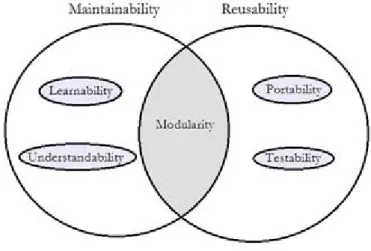
With this in mind, we can factorize the mutual complexity aspects of reusability and maintainability and end up with the same aspects which relate modularity. We can therefore describe modularity as a quality characteristic which relates to both maintain-ability and reusmaintain-ability (see figure 2.1).
Figure 2.1: Intersection of Maintainability and Reusability
There are also other quality attributes of which modularity is a quality characteristic. The table in Appendix A also shows which quality attributes modularity relates to.
2.3.2 Modularity Metrics
As quality characteristics have measureable properties like metrics, modularity also has some measurable properties which show to what degree an architecture is modular.
Galin [9] shows that there are a lot of metrics measuring different kinds of properties on different levels and stages of the development phase of a system. Some metrics measure implementation specific properties such as the number of lines of codes. Other metrics measure properties of the architecture.
In order to evaluate the degree of modularity of a system, metrics which measure the degrees of coupling, cohesion and granularity are needed.
Here is a collection of metrics that takes UML-diagram as input and which corresponds to these aspects.
Coupling Between Nodes (CBN)
This metric measures to what degree each physical node is dependent of other physical nodes. [7]
Description: Counts the number of dependencies that one node has to the other nodes
Level: System level Category: Coupling
UML diagram: Deployment diagram
Table 2.2: CBN
Degree of Component Coupling (DCOMC)
This metric measures the degree of each component’s consumed and provided depen-dencies. Each dependency is given a weight, if consumed, 1, and provided, 2, and then summarized into the metric’s value. [7]
Description: Counts all coupling provided and consumed by a component Level: Component level
Category: Coupling
UML diagram: Component diagram
Table 2.3: DCOMC
Coupling Between Components (CBCOM)
This metric counts all the dependencies that one component has to other components. [7]
Description: Counts all coupling of a component, both provided and con-sumed
Level: Component level Category: Coupling
UML diagram: Component diagram
Number of Classes per Component (NCPCOM)
This metric reviews the size and granurality for each component by counting its class components. [7]
Description: Counts number of classes in a component Level: Component level
Category: Size, Granularity
UML diagram: Component diagram, Class diagram
Table 2.5: NCPCOM
Number of Use Case per Component (NUCPCOM)
By looking at the use cases of the system a component is involved in, we can see the responsibilities for that component. [7]
Description: Counts use cases related to a component Level: Component level
Category: Cohesion
UML diagram: Component diagram, use case
Table 2.6: NUCPCOM
Number of Components per Use Case(NCOMPUC)
This metric measures how many components share the same responsibilities by looking at the sequence diagram for each use case and count the components involved. [7]
Description: Counts components related to a use case Level: Component level
Category: Size, Granularity
UML diagram: Component diagram, use case, sequence diagram
2.3.3 Tension between Modularity Related Quality Attributes “The more reusable we choose to make a software module, the more difficult that same software module is to use” [11]
In the quotation above Knoernschild [11] describes that there is a tension between the quality attributes maintainability and reusability. Knoernschild [11] continues his dis-cussion by stating that a higher degree of reusability is obtained in a finer-grained environment with many reusable modules. Maintainability on the other hand, is bet-ter treated in a more coarse-grained environment, if change occurs in a coarse-grained architecture the change is more likely to be isolated in one module. In a fine-grained reusable architecture change is more likely to affect multiple modules.
This means if we are going to measure the modularity of a system, we need to con-sider that some of the reusability aspects of modularity have a negative effect on the maintainability aspects of modularity.
2.4
Attribute-Driven Design
In order to make our study more readable, we will describe attribute-driven design (ADD).
Bass et al. [3] state that to be able to meet the quality- and functional requirements that are addressed by the system stakeholders, the architectural design needs to be formed on these requirements. Some of these requirements are tightly connected to the highest prioritized business goals; also these requirements are well suited for the so called architectural drivers [3]. The architectural drivers consist of the highly prioritized requirements which can be transformed into quality scenarios or use cases [3].
Bass et al. [3] describe quality scenarios as quality-attribute-specific requirements. They show how artifacts of the system react to stimulus and response. The response is mea-sured to show the impact of the stimulus. Figure 2.2 and the quote below illustrates a scenario of modifiability.
“A developer wishes to change the user interface to make a screen’s back-ground color blue. This change will be made to the code at design time. It will take less than three hours make and test the change and no side effect changes will occur in the behavior” p.77 in [3]
Figure 2.2: Modifiability Quality Scenario
In the mentioned quality scenario, the artifact is the system’s code, the stimulus is a developer wishing to change the UI and the response is that the modification was made with no side effects. The response is also measured in a given denomination, which in this case is time. The responses and measurement of responses can show to what degree a system meets different quality attributes.
The quality scenarios connected to the architectural driver should be the ones with the greatest impact on the architecture [3]. After the architectural drivers are identified the design phase of the system can be initiated.
ADD is used to design software architecture with an approach which is based on the architectural drivers which include the quality attributes that the software has to fulfill [3]. Bass et al. [3] describe this process as a recursive decomposition process where each stage or recursion step uses tactics and architecture patterns which help to assure a set of quality scenarios. The output or result of the ADD phase is a module decomposition view of the architecture and other views as appropriated. Not all details of the views result from an application of ADD; the output describes the system as a set of containers or modules for functionality and the interactions among them [3].
ADD can be seen as an extension or complementation of other more comprehensive development methods. For example, the Rational Unified Process (RUP) has an in-terception phase that handles requirement elicitation among other things. The ADD method can be incorporated right after the requirement elicitation has ended and then leave its output to the next phase of RUP [3]
There are three major steps in the ADD process depicted by Bass et al. [3]
1. Choose a module to decompose. In the first stage of recursion the module is most likely to be the whole system. All the constraints, functional and quality requirements that serve as input for the module should be available.
2. Redefine the module according to five sub steps:
a. Choose the architectural drivers from the set of concrete quality scenarios and functional requirements.
b. Choose an architectural pattern that satisfies the architectural drivers. The pattern should be based on the tactics that can be used to achieve the drivers. Identify child modules required to implement the tactics.
c. Instantiate the child modules and allocate functionality from the use cases and represent using multiple views.
d. Define interfaces of the child modules.
e. Verify and refine use cases and quality scenarios and make them constraints for the child modules.
3. Repeat the steps above in a recursive manner until no more decomposition is needed.
Measuring Software Quality
This chapter concerns the measurement of software quality. It will describe Deng and Mercado’s quality model and notation along with a summary of their mathematical model.
3.1
Deng and Mercado’s Method for Measuring Software
Quality
Deng and Mercado [7] propose a new method for evaluating software architecture on an architectural level. They start describing their method with a discussion about which quality attributes that they expect to be suited for measuring the quality of software architecture. As mentioned by Albin [2], quality attributes can be divided into those who are observable by execution and those who are not observable by execution. The ones not observable by execution are good candidates for the Deng and Mercado [7] method because these attributes can be measured from the static documents and models that describe the system’s architecture.
Furthermore, Deng and Mercado [7] propose a quality model where it is possible to plug in a quality attribute and use the output in a mathematical model which results show to what the degree the system is achieving the chosen quality attribute.
3.1.1 Quality Model
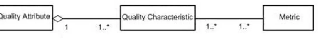
Deng and Mercado’s [7] proposed quality model is based on a traditional three-tier model which is illustrated in the figure below and includes Quality Attribute, Quality Characteristics and metrics.
Figure 3.1: Traditional Quality Model
The drawback of this traditional model is, as stated by Deng and Mercado [7], that a quality attribute can have different meanings for the overall system structure and for individual components’ internal structure. In addition, some metrics have a larger impact on a quality characteristic than others and there is a difference in how high metric values have a good or bad effect on the quality characteristics which it is related to.
As seen in the figure below Deng and Mercado’s [7] model extends the traditional model so it has two levels of quality attributes. The reason for this is that quality attribute separately affects the architecture as a whole along with each of the architecture’s com-ponents.
In addition to the two level of quality attributes, the relationship between quality charac-teristics and metrics is extended so that each association has a direct or reverse indicator which shows if a low or high value is desirable and a weight value to show the impact of each metric on its related quality characteristics.
Figure 3.2: Deng and Mercado’s Extended Quality Model
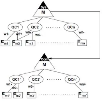
This extended three tier model is a static and descriptive model. In order to show the more dynamic behavior of a modeled quality attribute, Deng and Mercado [7] introduce a new modeling notation, shown in figure 5 on the next page. This notation projects
the static quality model into a model which shows the derived state of a specific quality attribute.
This modeling notation represents the two levels of quality attributes as triangles, one for system and another for component level attributes, denoted sys respectively com. Each quality attribute triangle has a set of associated quality characteristics, denoted QCn, which themselves have related metrics, denoted mn. Each metric is assigned a weight, denoted wn− or wn+, showing the metrics impact on its related quality characteristics.
This notation categorizes the values from the metrics applied to architectural data to the metrics’ related quality characteristics. This categorization is needed in order to use Deng and Mercado’s mathematical model successfully.
3.1.2 Mathematical Model
In order to make this thesis self contained we make a summary of the method proposed by Deng and Mercado in [7] below. We use the acronyms QA for quality attribute and QC for quality characteristic to increase the readability of this section.
Deng and Mercado’s mathematical model has three steps which correspond to three formulas:
1. For both system level metrics and component level metrics, integrate them to corresponding QCs.
2. Integrate component QCs to component QA.
3. Integrate system QCs and component QA to system QA.
3.1.2.1 Formula 1
Let d denotes a metric value. In order to normalize it, i.e. make it fit within the range of 0 and 1, we apply the following min − max formula (see e.g. [7]).
Here d ∈ [dmin, dmax] and x denotes the normalized value of d.
x = d−dmin
dmax−dmin if d 6= dmin∧ dmax
x = 1 if d = dmax
x = 0 if d = dmin
Each metric is assigned a weight. The weight is specified using a continuous empirical evaluation or based on previous work regarding the quality attribute. For instance, we know that cohesion and coupling are tightly connected with modularity; therefore the metrics associated with these aspects pay an important role in the measurement of modularity as a quality characteristic and needs to be weighted accordingly.
Another factor that induces the weighting of metrics is the context of which the system is formed in. For example the deployment views of embedded applications are simpler than enterprise applications; hence, the impacts of metrics related with deployment are different in the two types of applications. It is up to evaluators to define the weight in this case.
Describing the model further, each quality characteristic has i direct metrics and j reverse metrics. Each of these metrics is summarized together as the product of its
weight and value. The reverse metrics are optimized so that a preferable metric value is closer to 1 and an undesirable value is closer to 0. This is achieved by evaluating 1 minus the metric value.
QC = m1W1+ m2W2+ . . . + miWi+ (1 − m01)W 0 1+ (1 − m 0 2)W 0 2+ . . . + (1 − m 0 j)W 0 j QC = i X k=1 mkWk− j X k=1 m0kWk0 + j X k=1 Wk0
In order to make the result insensitive of the variation of selection of metric weights, the weights need to match the value 1. Without this normalization different indepen-dent studies would gain incomparable results. Note that we apply the same type of normalization in the rest of our thesis.
i X k=1 Wk+ j X k=1 Wk0 = 1
i is the number of direct metrics related with the QC
j is the number of reverse metrics related with the QC
mk ∈ [0, 1]
m0k ∈ [0, 1]
3.1.2.2 Formula 2
This formula integrates the components’ quality characteristic values, QCcom, into the
components’ quality attribute value, QAcom. Each QCcom is given a weight according
to its impact on the QAcom.
Consider the following illustrative example with maintainability as our considered as quality attribute. Here the set of characteristics are learnability, modularity and testa-bility. (see Figure 2.1 in section 2.3 how they relate) Each of these quality characteristics have values, denoted QCcom, which has been evaluated by formula 1. With the use of
these values, formula 2 summarize them into a single quality attribute value, QAcom.
There QAcom corresponds to the degree of how the components satisfy the quality
at-tribute maintainability. The result in this example and by this formula is a value which determines each components degree of maintainability.
QAcom=
|QCcom|
X
i=1
Where:
|QCcom|
X
i=1
Wi = 1
|QCcom| is the number of quality characteristic of a component
3.1.2.3 Formula 3
Just as the components have quality characteristics associated with the quality attribute under consideration, the system level of the architecture has its own set of quality char-acteristics for the same quality attribute being evaluated. These quality charchar-acteristics, QCsys, are summarized by the product of the QCsys value and its weight which purpose
is to the impact of the QCsys to system architecture being under evaluation.
Next the sum of all the components’ quality attribute value, QAcom, is s treated as an
extra system level quality characteristic. This is achieved by summarizing the product of each components’ quality attribute value, QAcom, and a weight which determines all
the component’s importance to the system architecture.
This extra quality characteristic is then added to the other system level quality charac-teristics in order to give the overall system quality attribute value, denoted QAsys.
As an illustration of the aforementioned description, consider the following scenario, maintainability again as our considered quality attribute. Before reaching this stage of the mathematical model all the system architectures components have its own main-tainability value. All of these values are multiplied with a weight which determines the individual components’ importance to the whole systems maintainability value.
The sum of the set of products of these multiplications is then multiplied with a new weight which determines all the components impact of the system. The product of this multiplication is then treated as an extra system level characteristic along with for example changeability, understandability and testability.
Finally all the system level quality characteristics, including the extra quality charac-teristic, are summarized into a single maintainability value.
QAsys = |QCsys| X i=1 QCsysiWi+ W|QCsys|+1× n X j=1 QAcomjWj0
Where: |QCsys+1| X i=1 Wi= 1 n X j=1 Wj0 = 1
|QC| is the number of QC of the System QA
n is the number of components of the architecture
After using this mathematical model the architecture will have a distinct value which shows in what degree the system fulfills the quality attribute evaluated. In addition to this, each component of the system will also have a quality attribute value indicating its own quality.
Our Case Study
4.1
The Melencolia Project
Melencolia is a software project which revolves around the idea of an Internet based treatment of depression among other psychiatric disorders.
The name Melencolia is taken from the famous engraving named Melencolia 1 which was created by the German artist Albrecht D¨urer (1471–1528) [4]. This engraving is full of cryptic symbols and messages along with a depiction of an angel which expresses emptiness and a low frame of mind, the name Melencolia also relates to the more modern term melancholia which is a symptom of depression [4].
The project was commenced with the realization that there is a need, in the domain of treating depression among other psychiatric disorders, for a more effective way for patients to access assignments and other types of material included in their treatment. These needs ended up in a requirements specification which illustrates a web-based system where psychologists can create and deploy customized treatment material for a given set of patients participating in a treatment.
The goal of the Melencolia project is to create a prototype system which can be used as a tool for determining the effectiveness of Internet based treatments and because the area of Internet based treatment is in its infancy, which makes the requirements unstable and variable, the system needs to be extensible and adaptable in order to support future occurrences of change. This means that the system’s components need to be easily maintainable, reusable and extensible.
4.2
Architectural Design of Melencolia Using ADD
As described in the previous section about the Melencolia Project, the components of Melencolia need to be reusable, maintainable and extensible and in section 2.3 about modularity we defined modularity as a characteristic of maintainability and reusability among other quality attributes. We therefore chose to use modularity as a prioritized architectural driver. This is done with the consideration that ADD focuses on quality attributes and not quality characteristics. This makes our application of ADD different from the standard scenario which uses quality attributes as architectural drivers. We see no problem with this approach as modularity, just as quality attributes, can be achieved with the aid of patterns.
Modularity as an architectural driver along with the other requirements of Melencolia, such as the functional and non-functional, were employed as input to ADD and this resulted in twelve recursion steps which instantiated the software elements of the system as modules with appropriate interfaces.
As the requirement elicitation process of Melencolia is an iterative process and not fin-ished in its current state, the architecture is not completed and ready for an implemen-tation stage. This does however not concern this thesis as we have enough architectural data to evaluate the degree of modularity of the architecture’s current status.
In order to use the ADD together with modularity, we need patterns which have a positive influence on the aspects of modularity. The patterns should therefore keep the coupling between software elements low and each software element as cohesive as possible.
The following patterns, aiding modularity, were applied (see Appendix C for descriptions of each pattern): • Module Fa¸cade [11] • Acyclic Relationships [11] • Cohesive Modules [11] • Abstract Factory [10] • Factory [10] • Decorator [10] • Code to an Interface [11]
• MVC [8]
• Front Controller [8]
• Client-Server [16]
4.2.1 Recursion Steps
The following paragraphs describe each of the recursion steps which transpired during the application of ADD.
Recursion One: As ADD proposes, the first input to the method are the constraints, quality attributes (in our case quality characteristic) and requirements of the whole system. In the initial recursion step, we chose to apply the following pattern: Client Server, which is more like a reference architecture or an architectural style [16] and the MVC pattern. These patterns revealed three software elements; the client part which included the view element and the server part which included the model element and controller element.
Recursion Two: In the next recursion step we chose to decompose the model element with the Cohesive Modules pattern. The output of this step revealed the following four subsystems or modules: Statistics System, User Management System, Treatment Management System and finally the Message Management System.
Recursion Three: This step involved decomposing the User Management System because of its imperative role in the system with several incoming dependencies. We applied the Module Fa¸cade Pattern and Cohesive Module Pattern. The output of this step concluded in two child modules: User Manager and Security Manager.
Recursion Four: This step decomposed the User Management System’s child module: User Manager. We applied the Abstract Factory Pattern during this recursion step. The responsibility of the User Manager is to create, delete and update users of the system.
Recursion Five: In order to conclude the decomposition of the User Management System, we chose to decompose the Security Manager with The Abstract Factory Pat-tern. The security manager handles authorization and authentication for the users and their corresponding actions in the system.
Recursion Six: This step included the decomposition of the Treatment Management System due to its business criteria. We applied the acyclic relationships and the Module Fa¸cade pattern. The output of this step was three software elements, a treatment builder module, treatment persistence handler and a parser module. The responsibility of the Treatment Management System is to allow doctors to dynamically create and store new treatment materials.
Recursion Seven: After decomposing the treatment management system we chose to decompose the treatment builder module due to its centric role for the whole treatment management system. We applied Factory, Abstract Factory, Decorator and Module Fa¸cade patterns to this module. As this module’s responsibility is to create new instances of treatment material, the factory and decorator pattern had significant importance during this step.
Recursion Eight: This step involved decomposing the parser module which responsi-bility is to convert serialized XML-data or database query results into runtime instances of treatment materials. We used Abstract factory to create an abstract parser factory which can be extended with new types of factories specialized on parsing different kinds of data.
Recursion Nine: The treatment persistence handler was the last module of the treat-ment managetreat-ment to be decomposed. We applied the Module Fa¸cade pattern to decrease coupling between the modules inside the treatment management system. The responsi-bility of the treatment persistence module is to handle the database interactions.
Recursion Ten: This step decomposed the statistics system which is used to gather results for the patients’ treatments. As the requirements of this module are not com-pletely developed the only pattern applied was code to an interface in order to make the module more extensible.
Recursion Eleven: The eleventh recursion step involved decomposing the Message System which purpose is to provide a message sending and receiving service for the system’s users. We applied Module Fa¸cade, Code to an interface and the factory pattern.
Recursion Twelve: Finally the last module to decompose was the front controller which serves as a backbone infrastructure to the entire system. The front controller’s
responsibility is to handle requests from the users and use the modules in the model to generate the desired result views and data for the users. The name Front Controller corresponds to a sub pattern of MVC which states that the system should have one distinct controller handling all requests and with aid of other system elements rout the requests between modules of the system. [8] At this stage of the Melencolia project the context specific details about the front controller’s functionality is not yet derived from the requirement specification.
4.2.2 Summary of the Application of ADD
The application of ADD on the Melencolia project resulted in a set of UML-Diagrams describing the architecture and its decomposition into modules with the module depen-dencies.
These diagrams can be found in Appendix D.
4.3
Our Proposed Method
As Deng and Mercado’s [7] method for evaluating software architecture focuses on tak-ing a quality attribute as input, it gives a more generic output of the quality aspects of that attribute. Because modularity is a quality characteristic associated to many different quality attributes and the fact that we want to use modularity as input for the measurement, we need to make some changes to Deng and Mercado’s [7] method.
We observe that the Deng and Mercado’s [7] quality model shows only a one to many association between the QA and its QC. This is mainly because Deng and Mercado’s [7] method only evaluates one attribute at a time. But as we want to focus on modularity which is a characteristic with associations to maintainability and reusability among others, we must refine their method in order to get a more specific result where the quality characteristics’ associated quality attributes are accommodated.
The weights and direction of different metrics may differ depending on which quality attribute the metric’s quality characteristic is related to. It is important to include that variation in both the quality model and the mathematical model. For instance, as stated before in the section about modularity (see section 2.3), the degree of decomposition of modules is more important when it comes to reusability than maintainability.
4.3.1 Our Proposed Quality Model Notation
To accomplish a successful measurement of modularity we have modified Deng and Mercado’s [7] quality model notation to acknowledge the diversion of quality attributes for each quality characteristic. Figure 4.1 shows our modification to Deng and Mercado’s [7] quality model notation. We have chosen to have the notation revolve around the quality characteristic instead of focusing on a single quality attribute.
As the measurment of modularty will vary depending on which of the quality charac-teristics related quality attribute we choose to look at, we need to change Deng and Mercado’s [7] notation to accommodate this difference. This means that each QC-QA relationship has its own set of metrics.
Let QA denote the set of quality attributes of our quality characteristic and let QAi,
where 0 < i < |QA|, denotes the i:th quality attribute of the QC, which stands for quality charectaristic. Here, SY S and COM denote System level and Component level of the architecture respectivly. Each of the metrics, mi, has a weight associated with it
which determines the degree of importance to the system architecture.
We have chosen to follow Deng and Mercado’s [7] notion of reverse and direct metric values, i.e. the higher the value of the reverse metrics, the more negative impact it has on the architecture and holds for direct metrics but with positive impact.
4.3.2 The Mathematical Model of our Method
The modification of Deng and Mercado’s [7] quality model notation also imposes us to revise their mathematical model. Our new proposed mathematical formula focuses on each QC-QA relationship, which is denoted by QCQA, in the model.
The formulas look as following:
4.3.2.1 Formula 1 QCQA= m1W1+ m2W2+ . . . + miWi+ (1 − m01)W 0 1+ (1 − m 0 2)W 0 2+ . . . + (1 − m 0 j)W 0 j QCQA= i X k=1 mkWk− j X k=1 m0kWk0 + j X k=1 Wk0 Where: i X k=1 Wk+ j X k=1 Wk0 = 1 (*)
i is the number of direct metrics related with the QCQA
j is the number of reverse metrics related with the QCQA
mk ∈ [0, 1]
m0k ∈ [0, 1]
Observe that our modification of the aforementioned formula is that instead of evalu-ating the value of a quality characteristic, the formula now evaluates the value of the relationship between a quality characteristic and a quality attribute. Also note that in (*), the weight formula is the same as in the formula by Deng and Mercado [7].
4.3.2.2 Formula 2 QAcom= |QCQA| X i=1 QCQAWi Where: |QCQA| X i=1 Wi = 1
Our modification to this formula integrates the different relationship values, QCQA, into
a single quality characteristic value, QCcom, for each component.
For instance, in the case of measuring modularity each component will have one reusabil-ity related value and one maintainabilreusabil-ity related value. These values will be integrated into a single component modularity value. In the summarization of the different QC-QA relationships each relationship is given a weight which corresponds to its impact on the component. 4.3.2.3 Formula 3 QCsys= |QCQA| X i=1 QCQAiWi+ W|QCQA|+1× n X j=1 QAcomjWj0 Where: |QCQA+1| X i=1 Wi = 1 n X j=1 Wj0 = 1
|QCQA| is the number of QC-QA of the System QC
n is the number of components of the architecture
This formula denotes QCsys as the overall quality characteristic of the whole system
architecture. In order to evaluate QCsys, all the QCcomvalues, calculated in the previous
formula, is merged into a single value which represents all the components’ quality characteristic. Each QCcom is given a weight which determines its importance to the
system.
This sum of each QCcom is also given a weight in order to scale the components’
impor-tance compared to the system level quality QC-QA relationships. Finally the system level QC-QA-relationships are integrated with the overall quality characteristic value of the system’s components. This result in a single value, QCsys, which shows in what
4.4
Evaluation of the Modularity in the Melencolia
Archi-tecture
In this section we will conduct our evaluation of modularity in the Melencolia archi-tecture. We start by an instantiation of our quality model with modularity as quality characteristic. Then we use this instantiated quality model as input for our mathemat-ical model. Finally the result of the application of our derived mathematmathemat-ical model on the architecture of Melencolia is illustrated in a set of tables.
4.4.1 Instantiation of the Quality Model
As we used modularity as a highly prioritized architectural driver in our application of the ADD-method on the specification of Melencolia, we will instantiate our proposed quality model with modularity as quality characteristic.
In order to demarcate the vastness of our case study we chose to exclude the quality attribute extensibility which among other quality attributes is associated with modu-larity. We chose to only look at maintainability and reusability because of the clear tension between these quality attributes, i.e. a high degree of one of the maintainability of an architecture has a negative impact on reusability, for a more detailed discussion see section 2.3. By this choice we are aiming at more interesting and analyzable results.
The figure below illustrates system and component level quality attributes along with the metrics associated with the apparent QC-QA relationships. The instance of the quality model denotes M A as maintainability and RE as reusability. The metrics are denoted by their acronyms which are described in section 2.3 about modularity metrics. Each metric is also given a weight direction and value by our empirical analysis of the metrics impact on the QC-QA relationship the metric is associated with.
The weights are assigned by us based on the guidelines of Knoernschild [11] and Albin [2] with respect to the tension between maintainability and reusability which are described in section 2.3. For instance, the metric number of classes per component determines the size of a component and the granularity of the whole system. In a reusability scenario, a more fine-grained system with many small components has positive impact effects. On the contrary, a system consisting of fine-grained components is harder to maintain due to complex relationships between the system’s components and that the responsibility of a requirement may be divided between many components. This has a negative impact on maintainability because changes in the requirements affects multiple components compared to a more coarse-grained system.
Figure 4.2: Instance of our Proposed Quality Notation with Modularity as Quality Characteristic
4.4.2 The Use of our Proposed Mathematical Model
As there are two levels of quality attributes we are obliged to categorize the metrics as system level and component level. We have categorized the metrics which evaluate larger scaled properties of our architecture as system level metrics because they cannot be applied to a specific component and the metrics which can be applied to specific components as component level metrics. For example, the metric number of components per use case is categorized as system level since there are multiple components involved in the evaluation of the metric which makes it impossible to use on a single component. On the contrary the metric number of use cases per component is evaluated specific to a single component and is therefore categorized as component level.
To be able to evaluate the modularity of our architecture we need to use the metrics associated with modularity on our UML-diagrams which describes the modular decom-position of the architecture. The tables below show the results of each metric, categorized by system level metrics and component level metrics.
The result of the metrics, denoted by their acronym (see section 2.3 for a detailed description of each metric), are displayed with both the metric value which is assessed from the UML-diagrams and the value resulting from using the normalization formula
which is denoted by N-value in the table heading and described in description of Deng and Mercado’s [7] mathematical model in section 3.1.2.
System Level Metrics
The two tables in this sub-section describe the system level metrics of the architecture of Melencolia. The last row in our table provides the average of the Values and N-Values respectively. We provide this average since our mathematical model requires a single value as an input of the system level metrics.
NCOMPUC
Use Case Value N-Value
Login 4 0,33 Logout 4 0,33 Delete User 3 0,00 Update User 3 0,00 Create User 3 0,00 Create Treatment 5 0,67 Update Treatment 3 0,00 Delete Treatment 3 0,00 Deploy Treatment 5 0,67 Associate User 3 0,00 Send Message 4 0,33 Read Message 4 0,33
Read Treatment Material 5 0,67 Calculate Result 6 1,00
Average 3,93 0,31
Table 4.1: Metric Values From NCOMPUC
CBN
Node Value N-Value
Database 1 0
Web server 2 1
Web browser 1 0 Average 1,33 0,33
Component NCPCOM NUCPCOM CBCOM DCOMC Value N-Value Value N-Value Value N-Value Value N-Value Message System 4 0,23 2 0,08 3 0,67 1,33 0,34 Treatment System 1 0,00 6 0,38 3 0,67 1,66 0,50 Statistics System 2 0,08 1 0,00 2 0,33 1,00 0,17 User Managment System 1 0,00 12 0,85 4 1,00 2,66 1,00 Front Controller 1 0,00 14 1,00 4 1,00 1,33 0,34 UserMangager 6 0,38 10 0,69 1 0,00 0,66 0,00 SecurityManager 6 0,38 2 0,08 1 0,00 0,66 0,00 TreatmentPersistanceHandler 1 0,00 5 0,31 2 0,33 1,00 0,17 ParseModule 4 0,23 3 0,15 4 1,00 2,00 0,67 TreatmentBuilderModule 14 1,00 3 0,15 2 0,33 1,33 0,34
Table 4.3: Component Level Metric Values
Component Level Metrics
The following table describes each component’s metric value, also assessed from the UML-diagrams which are the output from the ADD method on Melencolia, along with a normalized rendering of that value.
The Result
The tables below show the result from the application of our mathematical model on the architecture of Melencolia. We used the normalized metric values from the afore-mentioned tables and the relating weights as input for the mathematical model.
The first table shows the modularity values for each component together with another weight which determines the impact of maintainability and reusability respectively on the component. The assignment of the values of the weights is derived from the provided prioritizing of the requirements.
Component Maintainability Reusability Modularity
Weight Value Weight Value Weight Value
Message System 0,4 0,72 0,6 0,58 0,05 0,64
Treatment System 0,7 0,61 0,3 0,42 0,09 0,55
Statistics System 0,7 0,88 0,3 0,73 0,05 0,84
User managment System 0,5 0,26 0,5 0,044 0,09 0,15
Front Controller 1 0,33 0 0,19 0,05 0,33
User Manager 0,7 0,64 0,3 0,71 0,14 0,66
Security Manager 0,3 0,89 0,7 0,89 0,14 0,89
Treatment Persistance Handler 0,2 0,78 0,8 0,68 0,14 0,7
Parse Module 0,2 0,56 0,8 0,37 0,09 0,41
Treatment Builder Module 0,5 0,61 0,5 0,77 0,14 0,69
The last table describes the overall system level of modularity. The three first columns describe the system level QC-QA relationship and a summarized value for all the com-ponents’ degree of modularity. These values are weighted by their importance to the whole architecture and used in formula 3 (See 4.3.2.3) in order to get the overall archi-tecture degree of modularity. The aformentioned values of the weights are assigned by us according to the principle that components are of higher impact on the architecture of Melencolia than the system level QC-QA relationships.
Arcutecture Maintainability Reusability Components Modularity Weight Value Weight Value Weight Value Value
Melencolia 0,2 0,68 0,1 0,68 0,7 0,6 0,63
Table 4.5: The Modularity of Melencolia’s Architecture
The result shows that our current architecture of Melencolia has a modularity value of 0.63. This value does not tell us if our architecture has a low or high degree of modularity. We therefore conclude that there is a need for a validation of our method by evaluating more projects. The evaluation of other software architectures could build up a graph of usual and unusual results which can be used as reference values. The result of this validation can also be seen as a reference value for further refactoring of our architecture in order to achieve a higher degree of modularity. Another important aspect of the results of our method is that you can see which modules or components that are affecting the final value of modularity in a good or a bad way. This is discussed further in the next chapter.
Discussion and Conclusions
In this chapter we provide our derived answers on the posed research questions. The research questions are as follows:
• How can high modularity be achieved and evaluated in a software project on an architectural level?
• Establish a case study with help of ADD to achieve high modularity in a software project.
• How can we refine the method that Deng and Mercado presented in their work “A Method for Metric-based Architecture Level Quality Evaluation” [7], for the special case of modularity?
• Measure if we achieved the modularity qualities promised by ADD with our re-defined version of Deng and Mercado [7] metric-based software quality evaluation method.
We propose that high modularity can be achieved by using the ADD method and this follows from our empirical study on the Melencolia project. It is worth mentioning that in previous studies the architectural drivers in the ADD method have been quality attributes. However, in our study we deploy quality characteristics as architectural drivers and this is motivated by our observation that also desired quality characteristics of a system, e.g. modularity in Melencolia, can be achieved by choosing appropriate patterns. To the best of our knowledge, there are no earlier studies taking this approach.
Regarding appropriate methods on the evaluation of a quality characteristics fulfillment of a system (in our case we chose to focus on modularity) we conducted an investigation
on whether the method proposed by Deng and Mercado can be employed also in the evaluation of quality characteristics, in particular in the case modularity.
From our initial study we found that it is not possible to apply the aforementioned method without some modification. In addition to that fact, we observed some de-limitation with the method proposed by Deng and Mercado with respect to quality characteristics more specifically, this method consider only one quality attribute with a specific set of quality characteristics. In the case of modularity we need a method which accommodates the fact that quality characteristics such as modularity are asso-ciated with several quality attributes. We found out that the aforementioned change in the quality model requires a modification of the mathematical formulas in the ear-lier proposed method by Deng and Mercado. In this study we propose such a new method. Specifically, we propose a new quality model and derive a new set of math-ematical formulas for the measurement of modularity of a system’s architecture. We derive an architecture aiming at obeying high modularity and then apply our new pro-posed method in order to evaluate it. Our derived value here is 0.63 where 1 indicates an architecture obeying the highest form of modularity (impossible in a realistic, i.e., a fairly complex, system since it cannot include none dependencies between components).
The value 0.63 can be seen as an initial intuition of the degree of modularity in Melan-cholia’s architecture. We proposed that this can work as a reference value for further incrementing cycles of the design phase.
A continuation here is to look more closely at the component level values. By doing this we are able to determine which of the components will need further refactoring. The refactoring of components with low modularity value enhances the total value of the modularity of the architecture. For example in our case with the evaluation of the archi-tect of Melencolia the user management system component has only a modularity value of 0.15. This indicates that, in order to achieve a higher overall degree of modularity of the architecture this component needs to be refactored.
Another observation that follows from our analysis of the obtained value 0.63 is that one also needs to consider the tension between maintainability and reusability. More precisely, some of the metrics associated with these quality attributes will cancel each other out. For instance, a high value of the metric “Number of Classes per Component” has positive effect on the reusability attribute, and a negative impact in the case of maintainability where a low value in the metric “Number of Classes per Component” indicates a high maintainability.
A future work would be to conduct an accurate refactoring of the architecture of Melen-colia and this will most likely increase our obtained value even further. However note the
![Table 2.1: Union Between Different Quality Models [15]](https://thumb-eu.123doks.com/thumbv2/5dokorg/4154676.89453/15.893.221.726.434.883/table-union-between-different-quality-models.webp)