Building a Safety Case in Compliance
with ISO 26262 for Fuel Level
Estimation and Display System
Master Thesis in Intelligent Embedded SystemsSchool of Innovation, Design and Engineering M¨alardalen University
V¨aster˚as, Sweden
Author Raghad Dardar
Supervisors:
Barbara Gallina, M¨alardalen University Mattias Nyberg, Scania CV AB
Examiner:
Kristina Lundqvist, M¨alardalen University
Abstract
Nowadays, road vehicles, including trucks, are characterized by an increased complexity due to a greater variety of software, and a greater number of sen-sors and actuators. As a consequence, there is an increased risk in terms of software or hardware failures that could lead to unacceptable hazards. Thus safety, more precisely functional safety, is a crucial property that must be ensured to avoid or mitigate these potential unacceptable hazards. In the automotive domain, recently (November 2011), the ISO-26262 safety standard has been introduced to provide appropriate requirements and cesses. More specifically, the standard defines the system development pro-cess that must be carried out to achieve a system that can be considered acceptably safe. To be released on the market, systems must be certified, proofs that the systems are acceptably safe must be provided in terms of a structured argument, known as safety case, which inter-relates evidence and claims. Certification authorities are in charge of evaluating the validity of such safety cases. In the automotive domain, certification and compliance with the standard ISO-26262 is becoming mandatory. By now, trucks do not have to be compliant with the standard. However, it is likely that by 2016 they will have to. Scania is one of the leading companies in trucks development. To be ready by 2016, Scania is interested in investigating ISO-26262 as well as safety case provision. Thus this thesis focuses on the provision of a safety case in the context of ISO-26262 for Fuel Level Es-timation and Display System (FLEDS), which is one of the safety-critical systems in Scania.
Contents
1 INTRODUCTION 9
1.1 Context and motivation . . . 10
1.2 Contributions . . . 10
1.3 Organization of the thesis . . . 10
2 BACKGROUND and RELATED WORK 11 2.1 User Functions . . . 11
2.1.1 Implementation of User Functions . . . 11
2.2 FUEL LEVEL ESTIMATION AND DISPLAY . . . 12
2.2.1 FLEDS variants . . . 13
2.2.2 FLEDS Allocation Elements . . . 14
2.2.3 FLEDS Requirements . . . 15
2.3 HAZARD ANALYSIS TECHNIQUES . . . 17
2.3.1 Failure Modes and Effect Analysis . . . 17
2.3.2 Hazard and Operability Study . . . 19
2.3.3 Fault Tree Analysis . . . 22
2.4 ISO 26262 . . . 26
2.4.1 Management of functional safety . . . 28
2.4.2 Concept phase . . . 28
2.4.3 Product development at the system level . . . 31
2.4.4 Product development at the software level . . . 32
2.5 SAFETY CASE . . . 33
2.5.1 Safety Case in Compliance with ISO 26262 . . . 35
2.5.2 Safety Case Life Cycle . . . 35
2.6 Modelling Techniques . . . 37
2.6.1 Text-Based Notations . . . 37
2.6.2 Graphics-Based Notations . . . 37
2.7 Safety Case Fallacies . . . 42
2.8 Challenges when Developing Safety Cases . . . 43
2.9 D-Case editor . . . 43
2.10 Related Work . . . 45
4 SOLUTION METHODS 48
4.1 Scope . . . 49
4.2 Limitations . . . 49
5 COLLECTION AND PROVISION OF EVIDENCE 50 5.1 Hazard Analysis and Risk Assessment (Pt 3, Cl 7) . . . 51
5.2 Functional Safety Concept (Pt 3, Cl 8) . . . 53
5.3 Specification of the Technical Safety Requirements (Pt 4, Cl 6) 55 5.4 System Design (Pt 4, Cl 7) . . . 57
5.4.1 SESAMM . . . 58
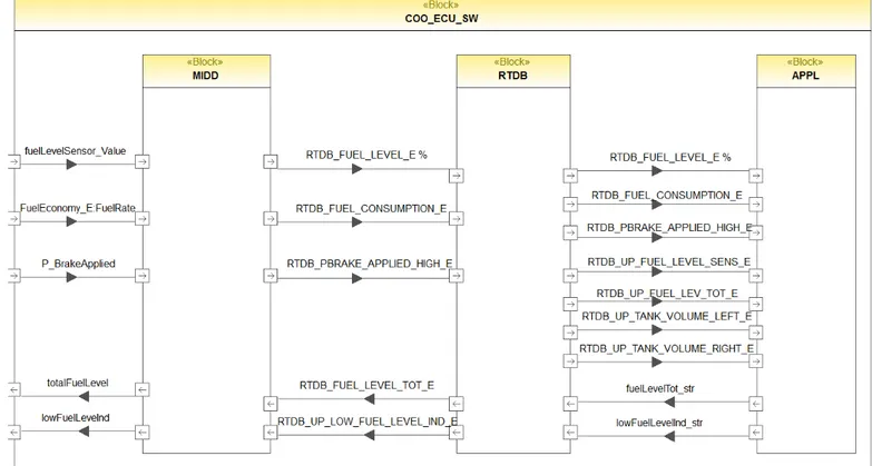
5.4.2 ECU software . . . 60
5.4.3 Software Layers in Coordinator ECU system . . . 64
5.5 Software Architectural Design (Pt 6, Cl 7) . . . 90
5.6 Item Integration and Testing (Pt 4, Cl 8) . . . 93
6 SAFETY CASE OF FLEDS 98 7 DISCUSSION 112 8 CONCLUSION AND FUTURE WORK 115 8.1 Conclusion . . . 115
8.2 Future Work . . . 116
Appendices 121
List of Tables
2.1 Configuration parameters for variant 1 of FLEDS . . . 14
2.2 UFRs for FLEDS . . . 15
2.3 AER 201 for FLEDS . . . 16
2.4 AER 201 for FLEDS . . . 16
2.5 Basic Sheet of FMEA . . . 18
2.6 Basic Sheet of HAZOP . . . 21
2.7 Classes of severity . . . 30
2.8 Classes of exposure . . . 30
2.9 Classes of controllability . . . 30
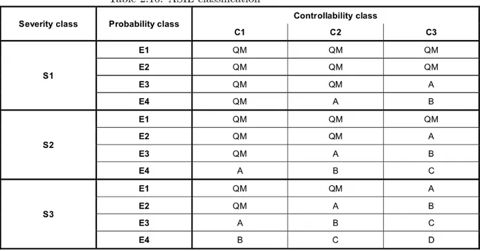
2.10 ASIL classification . . . 30
2.11 System design verification methods [17] . . . 31
2.12 Verification methods for the software architecture design [17] 32 2.13 Mapping of GSN elements to D-Case elements . . . 44
5.1 Hazard Analysis using Adapted HAZOP [5] for FLEDS . . . 52
5.2 Safety goals for FLEDS . . . 53
5.3 Functional safety requirements for FLEDS . . . 54
5.4 Technical safety requirements for FLEDS . . . 56
5.5 System design analysis methods . . . 75
5.6 FMEA for the system made at Scania-part 1 . . . 77
5.7 FMEA for the system made at Scania-part 2 . . . 78
5.8 FMEA for the system made at Scania-part 3 . . . 79
5.9 Safety related requirements of FLEDS that have been verified along with the verification methods used . . . 92
5.10 Mapping of Scanias testing levels for FLEDS to item integra-tion and testing in ISO 26262 . . . 94
5.11 Consistent and correct implementation of external and inter-nal interface at the hardware-software level [17] . . . 94
5.12 Test cases and results for the ECU system test in Scania that corresponds to hardware software integration and testing . . 96
5.13 Consistent and correct implementation of external and inter-nal interface at the vehicle level [17] . . . 96
5.14 Test cases and results for the vehicle integration system test and lab integration test for FLEDS in Scania that corresponds to vehicle integration and testing and system integration and testing in ISO26262 . . . 97 A.1 Standard deviation for both of the filters and the sensor in
List of Figures
2.1 Components of Fuel Level Estimation and Display (FLEDS) . 13
2.2 Basic process of FMEA [3] . . . 17
2.3 Basic process of HAZOP [3] . . . 20
2.4 Basic process of FTA [3] . . . 23
2.5 Event symbols for FTA . . . 24
2.6 Gate symbols for FTA . . . 24
2.7 FTA example . . . 25
2.8 Overall structure of ISO 26262 [17] . . . 27
2.9 Dependencies among the safety case elements [33] . . . 34
2.10 Safety case life cycle during traditional development life cycle [33] . . . 36
2.11 Normal prose example . . . 37
2.12 Structured prose example . . . 38
2.13 Argument outline example . . . 38
2.14 CAE modelling elements . . . 38
2.15 GSN modelling elements [9] . . . 39
2.16 Goal structure example [35] . . . 40
2.17 GSN extensions [9] . . . 41
2.18 Functional breakdown pattern [35] . . . 42
4.1 Solution methods used in this thesis . . . 49
5.1 Technical view of SESAMM . . . 59
5.2 Relations among ECU software layers . . . 60
5.3 internal functional view for the software of the ICL ECU system 61 5.4 Information flow among software layers in COO ECU system 63 5.5 Internal functional view of MIDD layer . . . 66
5.6 Internal functional view of fuel level display system . . . 68
5.7 Internal functional view of TankCalculation . . . 71
5.8 Internal functional view of AE201 . . . 73
5.9 Internal functional view of GainCalculation . . . 74
5.11 Fault tree for the deviation ”Fuel gauge indicates higher fuel
level than the actual fuel level in the tank” . . . 81
5.12 Fault tree for the deviation ”Fuel gauge indicates lower fuel level than the actual fuel level in the tank” . . . 83
5.13 Fault tree for the deviation ”Fault tree for the deviation Fuel gauge indicates no fuel level when it should not” . . . 84
5.14 Fault tree for the deviation ”Fuel level warning displayed when it should not” . . . 85
5.15 Fault tree for the deviation ”Fuel level warning not displayed when it should” . . . 87
5.16 Simulation result for the system when KF driven only by fuel consumption [23] . . . 88
5.17 Simulation result for the system when KF driven only by fuel level sensor [23] . . . 89
5.18 Simulation result for the system when KF driven by fuel con-sumption and fuel level sensor [23] . . . 89
5.19 Vehicle test results for the system when KF is driven only by fuel consumption [23] . . . 90
5.20 The verification model for the requirements of FLEDS using Model checking [30] . . . 91
5.21 Original sample for one of the test cases regarding ECU sys-tem test done for FLEDS at Scania . . . 95
6.1 Goal structure of FLEDS . . . 99
6.2 Goal structure for the product-based argument . . . 99
6.3 Goal structure for the Module D 3 . . . 100
6.4 Goal structure for the Module D 6 . . . 101
6.5 Goal structure for the Module D 7 . . . 102
6.6 Goal structure for the Module D 8 . . . 102
6.7 Goal structure for the Module D 10 . . . 103
6.8 Goal structure for the Module D 9 . . . 104
6.9 Goal structure for the Module D 12 . . . 105
6.10 Goal structure for the Module D 13 . . . 106
6.11 Goal structure for Module D 4 . . . 107
6.12 Goal structure for Module D 1 . . . 107
6.13 Goal structure for Module D 14 . . . 108
6.14 Goal structure for Module D 15 . . . 109
6.15 Goal structure for Module D 16 . . . 110
6.16 Goal structure for Module D 17 . . . 111
A.1 Simulation of the standard deviation for both of the filters and the sensor [31] . . . 123
ABBREVIATIONS
AE Allocation Element
AER Allocation Element Requirement APPL Application Layer
ASIL Automotive Safety Integrity Level
Cl Clause
COO Coordinator
EMS Engine Management System FAA Federal Aviation Administration FSR Functional Safety Requirement FTA Fault Tree Analysis
FMEA Failure Mode and Effect Analysis
FLEDS Fuel Level Estimation and Display System
HW Hardware
HAZOP Hazard and Operality Study ICL Instrument Cluster
KF Kalman Filter
MIDD Middle Layer
NGC New Generation Scania
Pt Part
PHA Preliminary Hazard Analysis RTDB Real Time DataBase
SG Safety Goal
SW Software
TSR Technical Safety requirement
UF User Function
1. INTRODUCTION
This chapter presents a brief introduction about the safety case, ISO 26262 and the system under study. Moreover, context and motivation and the organization of this thesis are presented further in the next sections. The need for safety cases that are used to argue and demonstrate the safety of the system has appeared. Safety case is a contextualized structured ar-gument that links evidence to claims to show that the system is acceptably safe. There are twdo types of arguments that are used to construct the safety case; product and process-based arguments. Product-based argument is an argument that is used to show that the behaviour of the system is safe by using evidence that is related to the product’s behaviour, whereas process-based argument is the one that is used to show that the process followed during the development life cycle is trustworthy. More details about these arguments are presented further in chapter 2.
With the introduction of safety standards such as ISO 26262, there was a change in the approach being followed in safety management as these standards provide the best practices that should be followed during the de-velopment, construction and operation of safety critical system.
Quoting from the standard: ISO-26262 is intended to be applied to safety-related systems that include one or more electrical and/or electronic (E/E) systems and that are installed in series production passenger cars with a maximum gross vehicle mass up to 3 500 kg. This thesis is about build-ing a safety case for Fuel Level Estimation and Display System (FLEDS), which is one of the safety-critical systems in Scania trucks. Indeed, a wrong behaviour (e.g. false fuel level) of such system could lead to hazardous events for the driver, such as engine stop and loss of power assisted steering. The focus of the thesis is to show how the different work products that are generated during the development life-cycle can be used to construct sub-arguments that are to be used to build the partial safety case. Moreover, the focus will be on collecting and providing (when missing) the evidence (product and process evidence) required for constructing the sub-arguments that are used to construct the safety case. In order to build a safety case in compliance with ISO 26262, mapping of what the system has to the standard is required. More detailed information about mapping is presented later in this thesis.
1.1
Context and motivation
Scania is interested in exploring ISO 26262 and the provision of the safety case. Therefore, the safety case is built in the context of ISO 26262. Only specific parts of ISO 26262 have been covered due to time limitation. This thesis will help Scania to address what is needed and missing in case Scania is interested in certification. Moreover, experiences from building a safety case in the context of ISO 26262 in an industrial setting are not so many and therefore such experiences are valuable and presented in the end of this thesis. Moreover, throughout this thesis, we will try to address the following questions:
• What does it mean to build a safety case in compliance with ISO 26262?
• What does it mean to have a clear separation between process and product-based arguments?
• What kind of work-products are required to be in compliance to the standard?
• What are the estimated effort for complete conformity with ISO 26262?
1.2
Contributions
The author of this thesis has provided a partial safety case for an indus-trial setting [FLEDS] in the context of ISO 26262. A clear separation be-tween product and process-based arguments have been maintained during this thesis as well. Moreover, a paper [25] presented at the 23rd Interna-tional Symposium on Software Reliability (ISSRE) has steemed from this thesis.
1.3
Organization of the thesis
The rest of the report is organized as follows: In chapter 2, essential back-ground necessary for this thesis as well as the related work are presented. In chapter 4, the solution methods used to achieve the results of this thesis are presented. In chapter 5, how we have collected or provided (when miss-ing) the evidence needed to develop illustrative process and product-based arguments through mapping are explained. In chapter 6, the safety case of the system is presented. Moreover, lessons learned and general guidelines to facilitate the adoption of ISO 26262 and the creation of safety cases are presented in chapter 7. Conclusion remarks and future work are presented in chapter 8. Finally, Contributions of this thesis are presented in section 1.2
2. BACKGROUND and
RELATED WORK
This chapter introduces the background information that are essential for this thesis. Section 2.1 introduces essential information about the concept of the user function in Scania. Consecutive sections introduce essential infromation about hazard analysis, ISO 26262 and safety case.
2.1
User Functions
In Scania, there’s a possibility to select different driver experience functions based on customer demands. These functions are called user functions (UF). UF is a function that the user can perceive on the vehicle level [29], for example air condition function is a UF since the driver can control the adjustment of the air condition. User functions can be seen as high level customer requirements [29].
2.1.1 Implementation of User Functions
To be able to implement UFs, one or more ECUs are required for each function. Each ECU unit consists of specific hardware and software that are needed to implement the specific UF. Moreover, communication among ECUs is also essential in order to have a complete working system. The following subsections explain what is required to implement a UF.
Electronic control unit
The electronic control unit (ECU) is a vital part to do all the required op-erations to implement the UF. Each ECU consists of hardware and software in which the hardware of an ECU consists of sensors and actuators. ECUs are the main components that are used in the electrical system of Scania which is called Scania Electrical System Architecture for Modularization and Maintenance (SESAMM).
Controller Area Network
The communication among different ECUs is established through a con-troller area network (CAN). CAN communication in SESAMM is divided into three buses which are red CAN bus, yellow CAN bus, and green CAN bus. The distribution of ECUs to these buses is as follows:
• The ECUs of the drive-line system are connected on a separate bus, the red bus. This is done to protect the drive-line functions from other less important functions from causing a failure on the bus. The ECU systems of the red bus are considered to be of highest criticality. These systems have criticality 1 [8].
• The ECUs of the most important systems that are not part of the drive-line are connected on a separate bus, the yellow bus, for the same reasons as given for the red bus. These systems have criticality 2 [8].
• The rest of the ECU systems are placed on the green bus. These systems have criticality 3 [8].
Allocation Element
Allocation element (AE) is a piece of code that is responsible for realizing a UF. Each ECU unit contains several AEs where each UF is realized by one or more AE.
2.2
FUEL LEVEL ESTIMATION AND DISPLAY
In this section, FLEDS is presented in order to understand how the system works and what are the components needed to build the system. There are different variants of FLEDS and only one variant is considered in this thesis. Therefore, FLEDS variants are presented in this section. Moreover, allocation elements for FLEDS are presented since it’s necessary to analyse AEs with respect to safety because AEs correspond to the code needed to implement the required functionality. The requirements of the systems are also necessary to be presented in this section in order to know later if these requirements have been met or not.
FLEDS has two major functions; Fuel level estimation and low fuel level warning. Truck driver needs to know how much fuel left in the tank and thus there’s a need for a function that will estimate fuel level and display it to the driver. Therefore fuel level estimation function will be used. Sometimes the driver doesn’t check the gauge frequently and thus there is a need for a mechanism that indicates that there’s low fuel level in the tank. Thus low fuel level warning function will be used to indicate to the driver that
a refuel is needed. Fuel level is measured and presented to the driver in the instrument cluster. If the fuel level is below a predetermined level a warning is presented in the instrument cluster as well. UF18 is responsible for FLEDS. The system consists of three ECU (Electronic Control Unit) systems which are Engine Management System (EMS), Instrument Cluster (ICL), and Coordinator (COO). In order to be able to estimate and check the fuel level in the tank, a fuel level sensor is essential, in which it will be placed in the tank. A signal from parking brake switch (PBS) is necessary for refuel detection purposes. A battery is used to provide a power supply for ECU systems.
Figure 2.1: Components of Fuel Level Estimation and Display (FLEDS)
2.2.1 FLEDS variants
FLEDS will be used in two types of vehicles and with two different types of fuel (liquid and gas). Thus there are four variants for fuel level display system:
1. Truck with liquid fuel 2. Bus with liquid fuel
3. Truck with gas 4. Bus with gas
For the simplicity of this thesis, only one variant is considered. The con-sidered variant is for truck with liquid fuel (variant 1) with one tank and one sensor. Moreover, there are different types of sensors and tank sizes. Therefore, only one sensor type and one tank size (left and right tank) is considered in this thesis. For the first variant of fuel level display system, the fuel level is estimated by COO.
Table 2.1: Configuration parameters for variant 1 of FLEDS
2.2.2 FLEDS Allocation Elements
Two allocation elements have been used for the realization of UF18 (Fuel Level Estimation and Display): AE 201 and AE 202. AE 201 and AE 202 are allocated in COO.AE 201 handles the fuel level estimation part. The following steps are carried out for fuel level estimation:
1. The fuel level sensor is connected to COO and the level of the fuel is read as a voltage value [27].
2. The voltage value is transformed into the corresponding volume in percentage of the total volume. The percentage value is used together with the total fuel capacity of the tank in litres to calculate the current fuel volume [27].
3. A kalman filter algorithm is used to estimate the fuel level. The last fuel volume estimate is used together with the current volume calcu-lated in step 2 and the fuel consumption from the engine to calculate a new estimate [27].
4. The estimated value from step 3 is transformed into a corresponding percentage value and sent to ICL for display of the current fuel level and to AE 202 for low fuel level indication [28].
AE 202 handles low fuel level warning. Information about the fuel level and tank capacity on the vehicle is used to activate a warning if the fuel level drops below a predefined level. The warning is kept even if the fuel level
Table 2.2: UFRs for FLEDS
for some reason increases again after the warning is set. Unusual driving environments, such as steep hills and tough terrain, can affect the fuel level to increase a short period even if no fuel is filled. However if the fuel level increases a lot, caused by for example a refill, the warning is unset again [28].
2.2.3 FLEDS Requirements
There are two types of requirements for FLEDS: User Function Require-ments (UFRs) and Allocation Element RequireRequire-ments (AERs). UFRs are used to describe the high level requirements for UF18 whereas AERs de-scribe how to implement UFRs. UFRs and AERs that have been covered in this thesis are presented below.
Table 2.3: AER 201 for FLEDS
2.3
HAZARD ANALYSIS TECHNIQUES
The objective of hazard analysis is to identify all the hazards that are caused by malfunctioning behaviour of electrical, electronic, or programmable items. A number of hazard analysis techniques are available nowadays. The tech-niques that are covered in the next sections are Failure Modes and Effect Analysis, Hazard and Operability Study, and Fault Tree Analysis. The rea-son why these techniques are explained is because they are in the context of this thesis.
2.3.1 Failure Modes and Effect Analysis
Failure Modes and Effects Analysis (FMEA) is a detailed, bottom up, in-ductive analysis technique that is used to identify the effects of the primary failure modes of subsystems, components, or functions, and to identify how to control or avoid the undesired effects of these failure modes. FMEA is primarily used for evaluation of the entire system when undesired failure modes occur. However FMEA can be used for hazard analysis as well. The technique provides a possibility to specify failure rates for the primary fail-ure modes, thus serving as a quantitative probabilistic analysis technique. FMEA is oriented towards detailed component and functional level. FMEA is also used to document the analysis and the design changes needed to reduce the risk associated to primary failure modes.
A. FMEA Process
Basic FMEA process starts by evaluating the design of the system. After evaluation, possible potential failure modes should be identified along with their possible causes. Effects of the specified failure modes should be considered. If possible, specifying recommended actions to reduce the risk of the potential failure modes is preferable. After following the previous steps, documentation of the results from those steps is essential. The output from FMEA process is a worksheet, as explained in the next paragraph
Figure 2.2: Basic process of FMEA [3] B. FMEA Worksheet
The information retrieved by performing FMEA is usually documented by using a worksheet. Many different types and formats of FMEA work-sheets have been suggested by different projects and disciplines over the
past years. The amount and type of information that should be cov-ered in the worksheet is determined by the project particular needs, the person that is performing FMEA, or the safety manager. The minimum information that must be presented in FMEA worksheet that supports hazard analysis is as follows:
• Failure mode: This field must be filled in with all the possible failure modes that may affect the item under examination.
• Failure mode causes: This field must be filled in with all the possible causes that result in the appearance of a particular failure mode. • Immediate effect of failure mode: This field must be filled in with
the direct effect of the failure mode that occurs on the next item in the design.
• System effect of failure mode: This field must be filled in with the effect of the failure mode that occurs on the system as a whole. • Detection methods of failure modes: This field describes how the
failure mode will be detected. If the method will result in detection of the failure mode before resulting in severe consequences, the detection methods can be specified as mitigation means.
• Current controls: This field must be filled in with the controls avail-able currently in the system that are used to prevent failure modes from happening or causing severe consequences.
• Recommended actions: This field must be filled in with the meth-ods that can be used for controlling, mitigating, or eliminating the effects of failure modes.
C. Advantages and Disadvantages
1. Advantages
• Easy to learn and perform
• Provides a structural way for evaluating systems, subsystems, and components
• Allows predicting the reliability of the item under analysis 2. Disadvantages
• Provide a way to identify failure modes related to multiple com-ponents failing together
• Provides less focus on failures resulting from human errors • Requires expertise in order to know what to analyse • Boring and time consuming
2.3.2 Hazard and Operability Study
Hazard and Operability study (HAZOP) is a qualitative analysis technique that is used to identify hazards by examining possible deviations in the de-sign of the system [3]. This technique is oriented to subsystems, components, software, environment, and human errors. The analysis can be performed at any level of the design such as conceptual design, high level design, or detailed system design. In order to be able to identify hazards using HA-ZOP, guide words, parameters, and presentation of the system design are required. Guide words are adjectives that are used to identify deviations in the design. Correct operation of the system is specified by the correct interactions among its components. Interaction among two components is established by passing a parameter, which will affect the correctness of the systems operation. To specify deviations, guide words are combined with parameters. Examples on guide words can be not supplied when demanded, supplied when not demanded, more, less, early, late, and etc. Knowledge about the system is necessary in order to be able to identify related devia-tions and hazards.
A. HAZOP Process
HAZOP analysis is conducted by a team and not by a single analyst. Success of HAZOP is determined by the appropriate selection of the team leader and team members. As depicted in Figure 2.3, the basic HAZOP process is constituted of the following steps:
• Establish HAZOP plan-In this step, the analysis goals and schedule are defined.
• Team selection-In this step, the appropriate team leader and team members are selected. Team members should have different disci-plines (e.g. design, testing, verification, and etc.)
• Define system elements-In this step, the desired system is divided into smaller subsystems. The decomposition process continues until all the items, component, or functions under analysis have been defines.
• Select guide words-In this step, the required guide words are de-fined.
• Perform analysis-This step involves many activities such as
– Identifying the appropriate parameters for every item, compo-nent, or function under analysis. The parameters will be the one that will decide the successful operation of the item. – Combine each parameter of the item with the appropriate guide
words in order to define deviations – Derive hazards from deviations
– Identify consequences for each particular hazard in order to know which hazards have severe consequences
– If possible, assign corrective actions for the hazards. Correc-tive actions can be assigned by preventing particular causes from happening
• Document process
In this step, the entire HAZOP process should be documented by using a worksheet.
Figure 2.3: Basic process of HAZOP [3] B. HAZOP Worksheet
The information retrieved by performing FMEA is usually documented by using a worksheet. The amount and type of information that should be covered in the worksheet is determined by the project particular needs, the team that is performing HAZOP, or the safety manager. Thus
the layout of the worksheet is not critical. The minimum information that must be presented in HAZOP analysis worksheet is as follows:
• No.: It’s used to identify each analysis line in the worksheet. The column is used for reference purposes.
• Item: This field specifies the desired item, component, or function for analysis.
• Function/purpose: This field specifies the purpose or the function of the item, component, or function under analysis.
• Parameter : This field specifies the parameter of the item, compo-nent, or function under the analysis.
• Guide word : This field specifies the guide word that will be used with the particular items parameter. It is important to note that more than one guide word can be defined for the particular param-eter.
• Deviation: This field identifies the particular deviation that results from combining the guide word with the parameter.
• Consequences: This field describes the consequences resulting from the identified deviation.
• Causes: This field describes the possible and the credible cause for a particular deviation.
• Hazard : This field describes the hazard that is resulting from a particular deviation.
• Risk : This field specifies the risk for the consequences of the partic-ular hazard. Risk will be measured by combing the severity of the consequences with the probability of occurrence for the particular deviation.
• Corrective actions: This field specifies the actions that will be used in order to mitigate or eliminate hazards.
Table 2.6: Basic Sheet of HAZOP
1. Advantages
• The technique is easy to learn and perform
• Structured and organized technique for hazard analysis • Can be applied to any type of system
• Help the team to discover and think about less obvious behaviours that may result in a deviation
2. Disadvantages • Time consuming
• Considers only single item deviations and not combination of items deviations
• Depends on the skills of the team
2.3.3 Fault Tree Analysis
Fault Tree Analysis (FTA) is a deductive failure analysis technique that is used to analyse a specific undesired event into its possible causes [3]. It is a top down approach since it starts with a top undesired event down to its causes. Undesired event is a failure that could lead to undesired con-sequences. Failure means that the system is unable to deliver the required functionality when needed. Failures can cause hazard, where hazard is a source of injury or harm to the environment or people. In reliability and safety engineering, it’s important to find the weakness points in the system design when a a specific failure occurs. Therefore, FTA is used to analyse safety-critical failures in those fields. The term undesired event may differ from one field to another. In Aerospace, system failure condition term is used instead of undesired event term. FTA requires a deep analysis of the possible causes for the undesired event. Moreover, the system under analysis might be complex. Therefore, FTA construction process can be exhausting and costly. The top event in the fault tree is the undesired event which is the root of the hazard. Every event that causes the top event should be described in the lower levels of the tree. The lower levels are used to show the relationship between the undesired event and its possible causes. The relationship between the undesired event and its possible cause are modelled using logical symbols and gates. More information about FTA modelling is presented in the upcoming sub sections.
A. FTA Process
The elements that are considered necessary in order to construct the fault tree are undesired event and the causes that lead to that event. The top undesired event should be resolved to its intermediate causes. The analysis process of the intermediate causes should continue until the fundamental causes are reached. The top event should provide a de-scription of WHAT the event is and WHEN it will occur. The event can be related to hardware fatigue, component (hardware or software) mal-function, mechanical components malmal-function, or a combination of the factors mentioned previously. It’s very essential to describe the top event correctly; otherwise it will result in wrong conclusions and evaluation of the systems design.
Figure 2.4: Basic process of FTA [3] B. FTA modelling
Modelling symbols are grouped between events, gates, and transfer sym-bols. Figure 2.5, and Figure 2.6 shows the symbols that are used in this master thesis for modelling FTA. Figure 2.5, shows the event symbols for FTA where there are two types of events that can be modelled, where
• Basic Event
represents the final basic cause for a specific intermediate event. • Intermediate event
represents the intermediate cause for a specific top undesired event. Figure 2.6, shows the logical gates that can be used to model the rela-tionship between the top event and its lower level causes. Gates work as follows:
• AND gate
This gate shows that the output event occurs if all input events occur.
Figure 2.5: Event symbols for FTA
• OR gate
This gate shows that the output event occurs if any of the input events occur.
Figure 2.6: Gate symbols for FTA
Figure 2.7, shows an example about a fault tree for the event The car doesn’t start during start up. The top event is caused either by a failure in the engine or a failure in the battery. The failure in the battery is caused by an electrical fault whereas the failure in the engine system is caused either by a communication fault or an engine fault. Modelling symbols can vary based on the software tool used for FTA construction.
Figure 2.7: FTA example
C. Advantages and Disadvantages
1. Advantages
• Show the logical relationship between the top event and all its possible causes
• Evaluate the current design of the system with respect to safety and reliability
• Find the gaps in the system
• Suggest effective safety mechanisms that can be used to get rid of the gaps in the system
• Enhance the testing and maintenance process. Since it provides an understanding about what can cause a failure then this point can enhance the testing process by using fault injection method during testing.
2. Disadvantages
• Time consuming technique • Needs training and experience
• Could lead to the production of large trees if the domain of the system is broad
• It may not succeed in addressing some problems as it’s a binary technique (either fail or success)
• Not possible to analyse combination of events in a single fault tree
Since every technique has its own strengths and weaknesses, it is preferred to use more than one technique for hazard analysis as they complement each other.
2.4
ISO 26262
ISO 26262 is a functional safety standard for road vehicles with a maximum vehicle weight of 3500 kg. The standard specifies a set processes (life-cycles) that have to be followed to achieve safety critical systems. The purpose of ISO 26262 is to reduce the risk of hazards that are caused by a malfunc-tioning behaviour of electrical, electronic or programmable safety critical systems. ISO 26262 consists of ten parts. Each part in the standard is divided into sub parts that are called clauses. Under each clause there are several requirements. In turn, each requirement has a number of sub require-ments. As it can be retrieved from Figure 2.8, ISO 26262 defines a life-cycle that is based on the V-model [ref]. This life-cycle which is followed from left to right is defined in parts 3-7 of the standard. In this thesis, the parts of the standard that mainly are considered are: Concept phase (Part 3), Product development at the system level (Part 4), Product developement at the software level (Part 6). Management of functional safety (Part 2) is also partially considered. Thus, the following subsubsections provide basic information on these parts and clauses.
2.4.1 Management of functional safety
This part is about safety management during different phases of the safety life cycle. It includes three clauses: Overall safety management, safety man-agement during the concept phase and the product development, and safety management after the items release for production. Overall safety man-agement clause specifies the requirements of safety manman-agement for the organization that is responsible for the development of the safety related item. One of the requirements prescribes that the organization should have a safety plan along with the process description of the plan. Another re-quirement prescribes that the organization should have a quality manage-ment according to a quality standard as well as a competence managemanage-ment that shows the competence of the people involved in the safety life cycle. The next clause, safety management during the concept phase and product development requires that a safety manager is assigned to be responsible for the whole safety management during Part3 to Part 7. This clause includes other requirements regarding the safety plan that will be followed during these parts. The last clause, safety management after the items release for production specifies the requirements for safety management when the item is released for production in order to ensure that the functional safety is achieved during the production process.
2.4.2 Concept phase
The first clause of this part is item definition. Item definition is used to identify the item and all the interactions that the item has with other items and the environment. Item is defined as a systems or a group of systems that implement one or more functionality that is observed at the vehicle level. The main purpose of this clause is to understand what will be developed and how it does work. The next step is to plan how the development according to ISO 26262 is to be made. This is done through initiation of safety life cycle clause.
The next step in the concept phase is the hazard analysis and risk as-sessment. In this step, all the hazards that are caused by malfunctioning behavior of electrical, electronic, or programmable items should be identi-fied. Hazard is an undesired event that results in harm to the humans or the environment. For each identified hazard, an automotive safety integrity level (ASIL) should is assigned. ASIL taxonomy consists of four levels that range from A to D, in which D is the highest and A is the lowest. ASIL is used to know which requirement of ISO 26262 to follow in order to reduce or avoid the risk of particular hazards. For each particular hazard that has an ASIL level A, B, C, or D, at least one safety goal is identified. A safety goal is a sentence that describes how to avoid or mitigate a particular hazard. The safety goal inherits the ASIL level of the particular hazard that it aims
to mitigate or avoid. The following is the requirements of hazard analysis and risk assessment that has been covered in this thesis:
• 7.4.2.2.1 The hazards shall be identified systematically by using a suit-able analysis technique.
• 7.4.2.2.2 Hazards shall be specifed in a way that can be observed at the vehicle level.
• 7.4.2.2.3 The hazardous event shall be specified by comining pertinent hazards and operational situations.
• 7.4.2.2.4 The consequences for each hazard shall be specified. • 7.4.3.1 All the specified hazardous events shall be classified.
• 7.4.3.2 For each hazardous event, the severity level shall be specified to one of the four levels S0, S1, S2 or S3 with respect to Table 2.7. • 7.4.3.4 TFor each hazardous event, the exposure level shall be
speci-fied to one of the four levels E0, E1, E2, E3 and E4, with respect to Table 2.8.
• 7.4.3.7 For each hazardous event, the controllability level shall be spec-ified to one of the four levels C0, C1, C2 and C3 with respect to Ta-ble 2.9.
• 7.4.4.1 For each identified hazardous event, an ASIL level is assigned using the parameters ”severity”, ”exposure” and ”controllability” with respect to Table 2.10.
• 7.4.4.3 A safety goal shall be specified for each hazardous event with an ASIL level A to D. If similar safety goals are specidied, these may be combined into one safety goal.
• 7.4.4.4 The safety goal shall inherent the same ASIL level for the cor-responding hazardous event. If similar safety goals are combined into a single one, with respect to 7.4.4.3, the combined safety goal shall inherent the highest ASIL level.
The next step in the concept phase is to define at least one functional safety requirement for each safety goal. Functional safety requirement is a sentence that describes the functionality to achieve the safety goal but it shouldnt describe how it will be implemented in hardware or software. Each functional safety requirement inherits the ASIL level of the particular safety goal. Allocation of functional safety requirement to the preliminary architectural elements of the item is essential. The derivation of functional
Table 2.7: Classes of severity
Table 2.8: Classes of exposure
Table 2.9: Classes of controllability
safety requirements, ASIL, and their allocation to the preliminary architec-ture is called functional safety concept. The requirements that has been covered in this thesis are as follows:
• 8.4.2.1 The functional safety requirements shall be deduced from the safety goals, taking into account the elementary architectural presump-tions.
• 8.4.2.2 At least one functional safety requirement shall be identified for each safety goal.
• 8.4.3.1 Every functional safety requirement shall be assigned to the elementary architectural presumptions.
2.4.3 Product development at the system level
The first clause in this part is planning of the work activities and it’s called initiation of product development at the system level. The next clause is to the specification of technical safety requirements for each functional safety requirement. Technical safety requirement specifies how to implement a functional safety requirement in hardware or software. Alloca-tion of technical safety requirement to hardware and or software is essential. Next step is to develop the system design based on the functional safety requirements, technical safety requirements, and non safety related require-ments. After developing the system design, verification of the system design shall be conducted with respect to the Table 2.11. Afterwards, the software architectural design shall be developed. The software architectural design shall be verified by using the verification methods listed in Table 2.12 [17]. Afterwards product development at the hardware respective soft-ware is conducted in which these parts are explained later in this thesis.
Table 2.12: Verification methods for the software architecture design [17]
The next step after product development at the hardware and software level is item integration and testing. The purpose of item integration and testing is to test every safety requirement in order to see if it is in compliance with its specification and ASIL categorization. Moreover, item integration and testing is used to verify that the items within the vehicle interact correctly. Item integration and testing is conducted at three levels: hardware-software, item, and vehicle level. The first level is to integrate and test the hardware and software of each particular element that compose the item. After that, integration and testing of all the elements that compose a particular item is conducted. Thereafter, integration and testing of all the items that compose the vehicle is conducted.
Thereafter in this part is safety validation. The purpose of safety val-idation is to provide evidence based on tests that the safety goals have been realized at the vehicle level. Moreover, safety validation is used to check whether the functional safety of the item is in compliance with the func-tional safety concept.
After that, functional safety assessment is conducted in order to evalu-ate the functional safety accomplished by the item. Thereafter, release for production clause is conducted. In this step, a check is made to see if the item meets all the considered requirements for functional safety. In case the item meets its requirements, release for production can start.
2.4.4 Product development at the software level
The first step starts with the planning of the work to be performed during this part. This step is called initiation of the product development at
the software level. The next step is to derive software safety require-ments from the technical safety requirerequire-ments along with the allocation of these requirements to software parts in a high abstraction level. Thereafter, software architectural design that meets software safety requirements is developed. The next step is to design and implement software units that are in compliance with the architectural design and the software safety requirements. Verification of the designed and implemented software units is followed. Next step is the software integration and testing in which is used to integrate all the software units and test them to demonstrate that the designed software architecture meets its software safety requirements. The last step is the verification of software safety requirements. The purpose of the verification of software safety requirements according to ISO 26262 is to demonstrate that the embedded software satisfies its require-ments in the target environment [17].
2.5
SAFETY CASE
A safety case is defined as an argument supported by evidence to show that the system is safe enough to operate in a given context [14]. The safety case should be understandable by different stakeholders, convincing about the safety of the system, as well as complete and consistent. The main elements of a safety case are requirements, evidence, argument, and context. More explanation about each of the elements is provided as follows:
• Requirements: are the safety requirements, goals, or objectives that must be achieved in order to ensure the safety of the system.
• Evidence: The evidence about the safety of the system. The evidence can be based on the development process, testing, verification, simu-lation, safety management, and analysis.
• Argument: It’s used to connect safety requirements to their evidence in a structured and a manageable way.
• Context: Identifies the domain or scope within which the safety to be argued.
It is mandatory for the safety case to have these four elements otherwise the case is not complete. An argument without evidence is baseless whereas evidence without an argument is unexplained [33]. The elements of the safety case are inter-related. Thus consistency must be maintained when a change is introduced in any of the safety case elements. For example, if a change has been introduced to the context, other elements should be checked to maintain if they are still valid in the context. Figure 2.9 shows
Figure 2.9: Dependencies among the safety case elements [33]
the elements of the safety case as well as the dependencies among these elements. The figure shows that the elements should be valid in the context. Based on the type of the evidence, the argument will be classified as either process-based or product-based. Process-based argument assumes that a good process will lead to a good product. Process-based safety case should provide evidence about the ordinary development process as well as the safety engineering process followed. Thus process-based argument can have two sub-arguments. The first sub-argument should provide a set of evidence to show that the development process used in the development life cycle is rigorous. The second sub-argument should provide a set of ev-idence to show that the safety engineering process used is effective. The other type of safety cases is the product-based argument. product-based argument should provide evidence that is related to the safe behavior of the product. Product-based evidence should show that the system has the required safe behavior when something wrong happens. The system should have fail-safe techniques. Fail-safe techniques result in a product that is more capable in handling all the considered failures. Fail-safe techniques can be either hazard mitigation or elimination techniques. These techniques should be considered in the design phase of the product. product-based argument should be supported by evidence from testing, verification, and simulation if possible.
2.5.1 Safety Case in Compliance with ISO 26262
Before the introduction of ISO 26262, the automotive industry has followed IEC 61508 international standard for electrical and electronic systems [16] and MISRA Guidelines for Safety Analysis of Vehicle Based Programmable Systems for development, operation and maintenance of safety electrical and electronic embedded systems. With the introduction of ISO 26262, require-ments about the safety case have been stated clearly in the standard. A safety case in compliance with ISO 26262 (as stated in Part 2, Management of Functional Safety [17]) should meet the following requirements:
”6.4.6.1 The safety case shall be complied with for items that have at least one safety goal with an ASIL (A), B, C or D: a safety case shall be developed in accordance with the safety plan”.
”6.4.6.2 The safety case should compile the work products that are gen-erated during the safety life cycle”.
The requirements means that the safety case should be developed for items with an ASIL level A or higher and it shall consist of a set of work prod-ucts that are generated by following the activities of ISO 26262 where work products means the result of performing one or more requirements of the standard . Requirement 6.4.6.2 encourages box ticking mentality as the com-pany or organization may pretend that it has a safety case in compliance with the standard just because it has the required work products.
2.5.2 Safety Case Life Cycle
A safety case is usually built at the end of the development life cycle. How-ever this approach has a number of disadvantages such as:
• The resulted safety case is less robust as the safety case developers will have to argue over the design as it’s given to them. Thus it will not be possible to influence the design in order to improve safety.
• The resulted safety case could lead to redesign and redevelopment of the system, in which it can be expensive with respect to time and money.
It is required by some safety standards such as U.K. Defense Standards 00-56 [26] to develop safety case during different phases of the development life cycle. Three versions of safety cases can be obtained based on in which phase the case is presented. These versions are as follows [33]:
• Preliminary Safety Case At this stage, the safety case is presented af-ter the systems requirements have been identified and reviewed. The
safety case in this stage will present the objectives, the arguing ap-proach as well as the anticipated evidence.
• Interim Safety Case At the interim stage, the safety case will be up-dated to reveal the knowledge from detailed design and system speci-fication.
• Operational Safety Case At the operational stage, the safety case will be updated with complete evidence that shows that the system meets its safety requirements. This safety case should be created before the system is put into service. Figure 2.10 shows the safety case develop-ment during traditional developdevelop-ment life cycle.
Figure 2.10: Safety case life cycle during traditional development life cycle [33]
2.6
Modelling Techniques
Based on the presentation of information used for describing the safety case arguments, modeling techniques can differ between graphics-based notations and text-based notations.
2.6.1 Text-Based Notations
This type of notation uses textual presentation to represent the elements of the safety case. Normal Prose, Structured Prose, and Argument Outline are some styles used for text-based notations. In normal prose, the safety argument is written as a normal text as presented in Figure 2.11. It can be difficult to understand and trace the structure of the argument in nor-mal prose. One way to solve this problem is to use structured prose, in which it requires to denote the structure of the argument by highlighting claim, context, evidence, strategy, solution, assumption, and justification. Figure 2.12, shows an example of a structured prose. The structure of the argument can be made clearer by using argument outline style. Different formats can be used in argument outline. Figure 2.13, shows an example of argument outline style. Other text-based notation styles are available such as mathematical proof and lisp style. Refer to [4] for more information about these styles.
Figure 2.11: Normal prose example
2.6.2 Graphics-Based Notations
This type of notation uses graphical presentation to represent the elements of the safety case. Claim Argument Evidence (CAE), and Graphical Struc-ture Notation (GSN) [36] are the notations used for graphical presentation of the safety case arguments. CAE has a number of modeling elements that represent claim, argument, evidence, and the relationships among these ele-ments. The basic argumentation elements that are used in modeling safety case arguments using CAE are given in Figure 2.14.
Figure 2.12: Structured prose example
Figure 2.13: Argument outline example
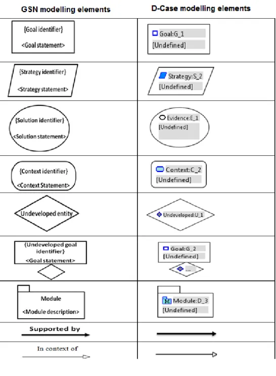
GSN uses basic argumentation elements to model the individual ele-ments of the safety case. GSN modeling eleele-ments are explained below, and presented in Figure 2.15.
• Goal: is a claim about the system
• Strategy: A method that is used when decomposing a claim or goal into sub claims or sub goals.
• Solution: represents evidence that shows that a particular goal or claim has been met.
• Context: definition of the domain or scope in which a goal, evidence or strategy is given
• Undeveloped entity: Indicate that specific part of the argument has not been developed. It can be applied to goals and strategies.
– Undeveloped goal: It indicates that the goal has not been devel-oped yet because the evidence supporting this goal is not available yet.
Figure 2.15: GSN modelling elements [9]
The argument is built by linking together the basic elements using two relationships that are solved by and in context of. The claim is continuously
decomposed into sub claims using GSN strategy element. The decomposi-tion continues until sub claims are supported by direct evidence. Linking together GSN elements in a network is called a goal structure. Figure 2.16, shows an example about goal structure. In this example, the top level goal G1 ”The control system is acceptably safe” in the context C1 ”Definition of acceptably safe” is broken down into sub goals G2 ”The possible hazards have been identified” and G3 ”The possible hazards have been mitigated” by using strategy S1 ”Argument over hazard identification and mitigation”. G2 and G3 are supported by direct evidence sol1 ”Hazop” and sol2 ”Verifi-cation” respectively.
GSN has two extensions: Patterns and Modular extensions [9]. Patterns are used for recording and documenting successful argument structures for reusability purposes [9]. The pattern can be reused when building a safety case for a system that has a similar domain as the pattern’s domain. The pattern should have a description that demonstrates the purpose, motiva-tion and other informamotiva-tion necessary about the pattern. It could result in improper use of the pattern in case those necessary information are missing. Figure 2.17 shows the extensions of GSN
Figure 2.17: GSN extensions [9]
Figure 2.18, shows a functional breakdown pattern as an example on GSN patterns. This pattern argues the safety of the system functions by arguing further that each of those functions are safe and by arguing that either the interaction among the system function are independent or the system functions are independent from each other (no interactions). This pattern is used in chapter 6 to construct the safety case of FLEDS. A safety case can grow in size and complexity for complex safety critical systems. Thus modularization can be used to construct modules of safety arguments.
Figure 2.18: Functional breakdown pattern [35]
2.7
Safety Case Fallacies
Flaws in the safety case are called fallacies. Undetected fallacies could lead to over trust of the systems safety. Therefore, fallacious argument could result in a system that has modes that could result in accidents. Falla-cies are widespread in safety arguments and in order to be able to detect them, awareness about them is required. Thus, logical fallacies have been categorized into the following [37]:
• Circular reasoning: Happens when the argument reassert its claim in a way that it makes it true.
• Diversionary arguments: contain enormous amount of insignificant material in order to divert the readers attention from a feeble sup-ported claim.
• Unsupported assertions: occur when an argument is not supported by evidence.
• Anecdotal arguments: concern arguments in which their claims are true in particular circumstances.
• Fallacious appeals: concern arguments that are supported by irrelevant evidence.
• Mathematical fallacies: contain common defects in mathematical in-ferences.
• Omission of key evidence: occurs when the argument lacks the neces-sary evidence to ascertain its authenticity
• Linguistic fallacies: Concerns arguments where the language is weak and distracting where such language could direct the reader to unde-sired conclusions.
A safety case expert can compare his arguments with respect to the different types of fallacies in order to see if the arguments have any underlying logical fallacies.
2.8
Challenges when Developing Safety Cases
Many challenges could appear while developing safety cases. Such challenges are:
• The person that is responsible for building the safety case can tend to show information that support safety and hide information that shows the opposite. This is called confirmation bias
• There’s a risk that the safety case becomes a paper practice in case the regulator demonstrate the required work products that the company has without actually checking the safety of the system.
• Safety case can increase in size and complexity for complex systems. Thus making it difficult to understand
• It can be difficult to organize and introduce evidence from different sources. Thus it’s difficult to keep up a clear structure of the safety argument
• It can be difficult for the reader to find where the relevant safety information can be found in the safety document
2.9
D-Case editor
D-Case editor has been used for the creation of the safety case. The goal of this thesis was not to make a survey between different tools due to time limitation of this thesis. D-Case is an editor for dependability cases where D stands for dependability. It’s implemented as an eclipse plugin and it has a framework for benchmark test [10]. The author of this thesis has decided to choose D-case editor because it is a user friendly and it provides support for modularity and GSN. Table 2.13 shows the mapping of GSN elements to D-Case elements.
2.10
Related Work
Based on our experience, there are few studies regarding the experience of building a safety case and certifying systems in compliance with ISO26262. Born et al. in [20] demonstrate the experiences from applying ISO26262 to a German car manufacturer. Even though the paper is not considering the issue of building a safety case, however, the experiences are important with respect to building a safety case in compliance with ISO26262. Born et al. experiences present three issues of applying the standard to car manufactur-ers. The first issue is that the company is accustomed to the existing internal safety processes and unwilling to the external obliged processes. The sec-ond issue is that the company is concentrating on the documentation rather than the contents of the documents. Moreover, the companies having diffi-culties in maintaining consistency among multiple documents and versions. This issue leads to the third issue; the problem of maintaining traceability among multiple documents. Born et al. suggests that traceability can be maintained by using cross-referenced identifiers among requirements, haz-ards and etc. The first issue of Born et al. is in consistent with the results of Kienle et al. presented in [1]. Kienle et al. results were based on an industrial questionnaire. The questionnaire showed that the internal code guidelines and processes are more important than the external ones. Johansson et al. in [18] demonstrate the gap analysis between the development life cycle of Scania and the requirements of ISO 26262. The gap analysis was conducted in order to define what is needed by Scania to achieve compliance with ISO 26262. The analysis of Johansson et al. showed that: No ASIL classification is conducted by Scania, requirement derivation by Scania is not performed as required by ISO 26262, and no planning for safety activities is conducted by Scania as required by ISO 26262. Johansson et al. suggests that Scania must focus on ASIL classification and the derivation of requirements in case Scania is interested in compliance with ISO 26262. ASIL classification and the derivation of requirements are essential sections of the standard. Fol-lowing other sections of ISO 26262 are dependent on both of those sections. Feather and Markosian in [21] present their experiences about building a safety case for a piece of a safety-critical software that is used to launch a Nasa’s vehicle. Their experiences present two issues. The first issue is that it was very difficult for them to start constructing the safety case as there were no examples about safety cases for software systems. The second issue is that it was hard to achieve a well-written and well-structured safety case. The authors of the safety case didn’t have a good understanding of how safety cases should be structured. In [6], T¨orner and ¨Ohman present an industrial study regarding the introduction of the safety case in the auto-motive industry. Their study was based on interviews and workshops. The first issue from their study showed that the main concept of the safety case was not used. Moreover, the results showed that it was difficult to collect
information for building safety cases. Moreover, competence and experience are required when building safety cases. In this thesis, similar issues were experienced as presented in chapter 7.
3. PROBLEM
FORMULATION
This thesis consider applying ISO 26262 and building a safety case on an industrial setting. The author of this thesis will try to show how the different work products that are generated during the development life cycle can be used to construct the safety case. Moreover, throughout this thesis we will try to address the following questions:
• What does it mean to build a safety case in compliance with ISO 26262? This question direts us to the following subquestions:
– How to make the safety case in compliance with the standard? – How to find the evidence relevant to build the safety case? • What does it mean to have a clear separation between process and
product-based arguments? This question opens the door to another one which is; what makes a work product a process-based evidence and what makes it a product-based evidence?
• What are the main challenges that may appear when applying ISO 26262 and building the safety case?
4. SOLUTION METHODS
This chapter presents the solution methods that have been used to perform this thesis as well as the scope of this thesis. Moreover, the limitations of this thesis with respect to the time limit and the documents that has been found for the system are presented further in this chapter.
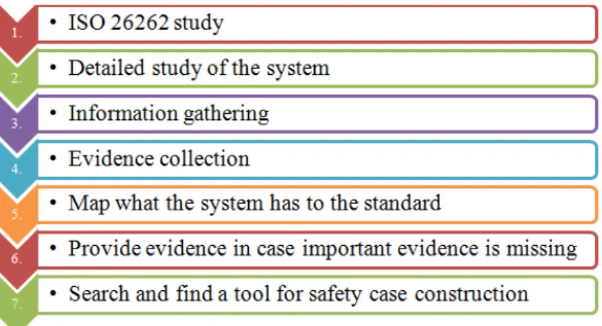
In order to be able to perform this thesis in a structured way, a number of steps have been taken. The first step is to study ISO 26262 in order to be able later to map what has been found for the system to the standard in order to produce process-based evidence that is in compliance with the standard. ISO 26262 study has been conducted in section 2.4. Thereafter, a detailed study of the system under analysis is conducted as presented in sec-tion 2.2. If informasec-tion needed about the system is missing, interviews are conducted to gather relevant information (information gathering). There-after, evidence about the safe behaviour of the system and the process that has been followed during the system development are collected as presented in chapter 5. The next step is to map what the system has to the standard and in case of absence of important evidence, evidence should be provided. The mapping is presented in chapter 5. The last step is to search and find a tool for constructing the safety case as presented in section 2.9. Figure 4.1 shows these steps. The resulting safety argument can be ambiguous and un-understandable because not all engineers are able to write clear, well reasoned, and well structured English. To overcome the limitations of text-based notations, graphical structure notations are used as explained before in subsection 2.6.2. GSN is the one that has been used in this thesis because of:
• Ease of construction and management of the safety argument • Easy to understand the logical flow in the safety argument • Ease of maintenance
• Tool support
• Modularity and patterns support
To make the construction of the safety case easier, a tool that supports modularity is needed. Thus, searching and finding a suitable tool is essential.
Figure 4.1: Solution methods used in this thesis
4.1
Scope
The scope of this project is to develop an operational safety case for FLEDS because the system is already in the production phase and the evidence regarding the system safety is present.
4.2
Limitations
• With respect to the time limit of the thesis and with respect to what documents have been found regarding the system, the work covers only the software functions of the system. Therefore, the hardware of the system haven’t been analysed with respect to safety.
• The parts of ISO 26262 that has been covered in this thesis, are based on what have been found for the system under analysis. The system is studied and each activity that is implemented for the system is checked against ISO to see to which part of the standard it corresponds.
5. COLLECTION AND
PROVISION OF
EVIDENCE
To build a safety case, first of all, the claims to be supported must be clear and the evidence to support them must be identified. Usually, the top-level claim is that the system is acceptably safe with respect to the definition of acceptably safe. This top-level claim is shown to be founded by providing evidence that all the hazards that lead to intolerable risk are mitigated. This top-level claim stems from the objective of ISO 26262, which states that the product should ensure an adequate and acceptable level of safety. Our work has not consisted in making a cost and benefit analysis to achieve a definition of acceptably safe for which the risk is as low as reasonably practical. Instead, we have proceeded as if a definition was present or at least could be provided in further developments of this work. Our main focus has been in finding a clear mapping between the evidence required by the standard and the evidence available in the company. This mapping was needed to understand which evidence could be collected to build the safety case and which evidence was missing and needed to be provided. To do such mapping, we thoroughly studied FLEDS, ISO 26262 and the safety life-cycle adopted by the company. Moreover, interviews have been conducted with the employees who were involved in the development of the system. Therefore, in this section, a mapping of what the system has to the standard is presented. The clauses that are covered in this section are based on what have been found and or provided for the system regarding hazard analysis, design, testing, verification and etc.
5.1
Hazard Analysis and Risk Assessment (Pt
3, Cl 7)
As stated in the background subsection 2.4.2, the objective of hazard analysis and risk assessment is to identify and classify all the hazards that are caused by malfunctioning behaviour of electrical, electronic, or programmable items. No hazard analysis and no ASIL classification have been made in Scania since the standard is not adopted. Thus, evidence about hazard analysis, ASIL classification and safety goal identification was essential. Thus this evidence has been provided by the author of this thesis. HAZOP technique has been used for hazard analysis and more fields to the HAZOP sheet have been added in order to make it in compliance with ISO 26262. UFR of FLEDS corresponds to SG. Thus a mapping from UFRs to SGs is conducted for the spec-ification of SGs. Both, the requirements of hazard analysis and risk assessment in the background subsection 2.4.2 and the hazard analysis techniques suggested in the course DVA321 [5] has been followed when providing an adapted HAZOP table.
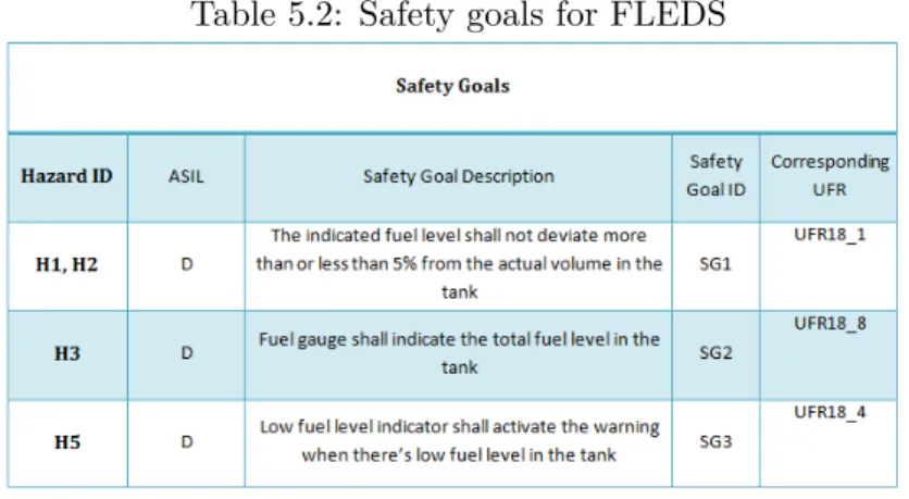
Hazard analysis has been conducted for the main two functions of FLEDS (fuel level estimation and low fuel level warning). Adapted HAZOP technique has been selected for hazard analysis. Table 5.1, shows HAZOP analysis for FLEDS. To make ASIL classification much more clear, colours has been used such as red, orange and green where red stands for ASIL level D (catastrophic), orange stands for ASIL A, B, and C, and green stands for No ASIL level or QM level. Safety goals have been formulated as it is required in requirement 7.4.4.3 and 7.4.4.4 in the background subsection 2.4.2. Table 5.2, shows the safety goals that are formulated for each hazard.

![Table 2.11: System design verification methods [17]](https://thumb-eu.123doks.com/thumbv2/5dokorg/4693087.123152/32.892.183.745.843.1024/table-system-design-verification-methods.webp)
![Figure 2.10: Safety case life cycle during traditional development life cycle [33]](https://thumb-eu.123doks.com/thumbv2/5dokorg/4693087.123152/37.892.172.810.552.776/figure-safety-case-life-cycle-traditional-development-cycle.webp)
![Figure 2.15: GSN modelling elements [9]](https://thumb-eu.123doks.com/thumbv2/5dokorg/4693087.123152/40.892.179.774.599.984/figure-gsn-modelling-elements.webp)